HAL Id: tel-02307383
https://tel.archives-ouvertes.fr/tel-02307383
Submitted on 7 Oct 2019
HAL is a multi-disciplinary open access archive for the deposit and dissemination of sci-entific research documents, whether they are pub-lished or not. The documents may come from teaching and research institutions in France or abroad, or from public or private research centers.
L’archive ouverte pluridisciplinaire HAL, est destinée au dépôt et à la diffusion de documents scientifiques de niveau recherche, publiés ou non, émanant des établissements d’enseignement et de recherche français ou étrangers, des laboratoires publics ou privés.
Numerical modelling of coupled adiabatic shear banding
and micro-voiding assisted dynamic ductile failure
Hannah Lois Dorothy
To cite this version:
Hannah Lois Dorothy. Numerical modelling of coupled adiabatic shear banding and micro-voiding assisted dynamic ductile failure. Mechanics of materials [physics.classph]. Université Paul Sabatier -Toulouse III, 2018. English. �NNT : 2018TOU30176�. �tel-02307383�
THÈSE
En vue de l’obtention du
DOCTORAT DE L’UNIVERSITÉ DE TOULOUSE
Délivré par l'Université Toulouse 3 - Paul Sabatier
xxxxxxxxxxxxxxxxxxxxxxx Présentée et soutenue par
Hannah Lois DOROTHY
Le 15 octobre 2018
Modélisation numérique de la rupture ductile
dynamique par cisaillement adiabatique et
micro-endommagement couplés
Numerical modelling of coupled adiabatic shear
banding and micro-voiding assisted dynamic ductile
failure
xxxxxxxxxxxxxxxxxxxxxxxxxxxxxxxxxxxxxxxxxxxxxx
Ecole doctorale : MEGEP - Mécanique, Energétique, Génie civil, Procédés Spécialité : Génie mécanique, mécanique des matériaux
Unité de recherche :
ICA - Institut Clément Ader
Thèse dirigée par
Patrice LONGERE
Jury
Mme Patricia VERLEYSEN, Présidente M. Sébastien MERCIER, Rapporteur
M. Laurent STAINIER, Rapporteur M. André DRAGON, Examinateur M. Xavier SOLDANI, Examinateur M. Patrice LONGERE, Directeur de thèse
THÈSE
En vue de l’obtention du
DOCTORAT DE L’UNIVERSITÉ DE TOULOUSE
Délivré par l'Université Toulouse 3 - Paul Sabatier
xxxxxxxxxxxxxxxxxxxxxxx Présentée et soutenue par
Hannah Lois DOROTHY
Le 15 octobre 2018
Modélisation numérique de la rupture ductile
dynamique par cisaillement adiabatique et
micro-endommagement couplés
Numerical modelling of coupled adiabatic shear
banding and micro-voiding assisted dynamic ductile
failure
xxxxxxxxxxxxxxxxxxxxxxxxxxxxxxxxxxxxxxxxxxxxxx
Ecole doctorale : MEGEP - Mécanique, Energétique, Génie civil, Procédés Spécialité : Génie mécanique, mécanique des matériaux
Unité de recherche :
ICA - Institut Clément Ader, CNRS UMR 5312
Thèse dirigée par
Patrice LONGERE JURY
Patricia VERLEYSEN Professeur, Universiteit Gent Présidente
Sébastien MERCIER Professeur, Université de Lorraine Rapporteur
Laurent STAINIER Professeur, École Centrale de Nantes Rapporteur
André DRAGON Directeur de Recherche Émérite, Institut Pprime Examinateur
Xavier SOLDANI Professeur Assistant, Universidad Carlos III Examinateur
i
Abstract
High strength metallic materials, notably steel and light-weight titanium and aluminium alloys, are widely used in aeronautical and other structures. In case of accidental overload involving high strain rates and quasi adiabatic conditions, these materials are often susceptible to adiabatic shear banding. The adiabatic shear bands (ASB) are intense shear localisation zones resulting from thermomechanical instability and provoking premature material failure. At an advanced stage of the localisation process, the ASBs have been shown to contain micro-voids (MV) which may coalesce to form cracks and ultimately lead to the fracture of the structure. Thus the coupled mechanisms of ASB+MV act as a precursor to catastrophic failure and it is consequently crucial to numerically model their formation and effects when dealing with structures submitted to high loading rates. The ASBs are also observed in industrial applications such as high speed machining where their formation favours the chip serration.
A large scale postulate is used herein to obtain a global insight into the structural material response. The shear band cluster is indeed contained/ embedded within the representative volume element (RVE), and not the opposite as usually considered. The objective here is to enrich a model describing the ASB effects by taking into account the consequences of the micro-voiding within the progressive failure process. The effects of ASB and MV initiation and evolution on the RVE (material point) response are double: kinematic, namely a progressive deviation of the plastic flow in the band plane described via specific ASB and MV induced velocity gradients; and material, namely a progressive anisotropic degradation of the elastic and plastic moduli described via ASB and MV induced second order tensor deterioration variables. The ASB onset criterion is derived from the linear perturbation analysis and the MV is activated using a critical value for the local energy release rate. The interest of this advanced constitutive model is emphasised by comparison with an application oriented (1-D) model where D is a scalar damage variable.
The enlarged ASB+MV model is implemented as user material into the engineering finite element (FE) computation code LS-DYNA in the context of standard FE kinematic formulation. The dynamic shear compression loading of a hat shaped structure is simulated; the contributions of the ASB on the one hand and MV on the other hand could be clearly identified and in agreement with experimental results. Moreover, the limitation of the current numerical approaches to simulate the high speed machining is evidenced.
ii
Résumé
Les matériaux à haute résistance, notamment les aciers et les alliages à base d’aluminium et de titane, sont largement utilisés dans l’aéronautique comme matériaux structuraux et de protection. Dans le cas de surcharges accidentelles impliquant des vitesses de chargement élevées et des conditions quasi adiabatiques, ces matériaux sont souvent sensibles au cisaillement adiabatique par bande. Les bandes de cisaillement adiabatique (BCA) sont des zones étroites de cisaillement intense qui résultent d’une instabilité thermomécanique et qui conduisent à une rupture prématurée du matériau. À un stade avancé du processus de localisation, des micro-cavités (MCs) ont été observées dans les BCAs. Ces MCs peuvent coalescer pour former des fissures et mener à la rupture de la structure. Ainsi, les mécanismes couplés d'ASB+MC agissent comme un précurseur à la rupture catastrophique et il est par conséquent important de modéliser numériquement leurs effets dans des structures soumises à des sollicitations à haute vitesse. Les BCAs apparaissent aussi dans certaines applications industrielles, telles que l’usinage à grande vitesse, où elles favorisent le festonnement du copeau.
Un postulat de grande échelle est appliqué ici où la longueur caractéristique du volume élémentaire représentatif (VER) est plus grande que la largeur de bande, et non l’inverse comme fait communément. L'objectif du travail présenté est d'enrichir un modèle décrivant les effets des BCAs en prenant en compte les conséquences de l’endommagement par MC dans le processus progressif de la rupture. Les effets des BCAs et des MCs sur la réponse du VER sont doubles : cinématique, à savoir une déviation progressif de l’écoulement plastique dans le plan de la bande décrite via des gradients de vitesse induits par les BCAs et par les MCs; et matériel, à savoir une dégradation anisotrope des modules élastiques et plastiques décrite via des variables tensorielles d’ordre deux de détérioration induite par les BCAs et par les MCs. L’amorçage des BCAs est déterminé à partir d’une analyse linéaire de stabilité et celui des MCs par une valeur critique du taux de restitution d'énergie local. L’intérêt de ce modèle avancé est démontré par comparaison avec un modèle orienté application du type (1-D) où D est une variable de détérioration isotrope.
Le modèle enrichi ASB+MC est implémenté comme matériau utilisateur dans le code de calculs commercial par éléments finis LS-DYNA. La simulation du chargement dynamique de cisaillement par compression d’une éprouvette chapeau a été conduite ; les contributions des BCAs d'une part et des MCs d'autre part dans la détérioration de la structure sont clairement identifiées et en accord avec les résultats expérimentaux. De plus, la limitation des approches numériques actuelles pour simuler l'usinage à grande vitesse est mise en évidence.
iii
Acknowledgements
Above all, I thank my Lord Jesus Christ for His saving grace, everlasting mercies and bountiful blessings in my life. I thank Him for bestowing upon me His grace and wisdom, enabling me to successfully complete my PhD.
Firstly, I would like to express my sincere gratitude to my PhD supervisor Prof. Patrice Longère for his diligent guidance, patience, motivation and support throughout the course of the PhD. The regular review meetings and discussions proved extremely helpful in the progress of the research work. I wholeheartedly thank him for the meticulous correction of all the written articles and the present thesis. I am thankful to him for giving me the opportunities to present our research work in several conferences and to teach master’s student. I am indeed blessed to have had such an excellent PhD supervisor and a mentor. I would always remain grateful to him.
I thank Dr. Xavier Soldani of Universidad Carlos III for the collaboration on the simulation of high speed machining.
I sincerely thank each of the jury members for having examined this work.
I truly appreciate each of my fellow PhD students at Insitut Clément Ader for providing a warm and friendly environment and for the moments of sharing and fun. I am pleased to thank my former officemate Dr. Johannes Wolf for all his advice and help when I first started my PhD. It was absolutely amazing to share my office with Miguel Ruiz De Sotto, having lots of insightful discussions, fun and small talk. I express my heartfelt thanks to Gunasilan Manar and Norazrina Binti Mat Jali for their company and aid in times of need. Last but not least, I would like to thank my parents and my sister for their love and support. Words cannot express how grateful I am to my mother, who has always been a pillar of strength, for all her prayers, selfless love and encouragements throughout my PhD and all along.
iv
Scientific Communications
International peer reviewed article
[ACL1] H.L. Dorothy and P. Longère. Modelling of high strain rate Adiabatic Shear Banding induced failure: a
comparison of two approaches. Int. J. Impact Engineering. 110, 219-227. 2017 doi.org/10.1016/j.ijimpeng.2017.02.024
[ACL2] H.L. Dorothy, X. Soldani and P. Longère. Adiabatic Shear Band assisted chip serration in High Speed
Machining: Some Modelling Issues. Submitted to J. Adv Mat. Process. Tech. Journal article without peer-review
[ASCL1] H.L. Dorothy, P. Longère and A. Dragon. Coupled ASB-and-microvoiding-assisted Dynamic Ductile Failure. Procedia Engineering. 197, 60-68. 2017 doi.org/10.1016/j.proeng.2017.08.082
[ASCL2] H.L. Dorothy, P. Longère and A. Dragon. Modelling of high strain rate failure under ASB and microvoiding. Procedia Engineering. 173, 593-600. 2017 doi.org/10.1016/j.proeng.2016.12.107
National or International conference proceedings
[ACT1] H.L. Dorothy and P. Longère. Dynamic failure of viscoplastic materials under ASB and micro-voiding.
Accepted in EPJ web of conference. 12th International DYMAT Conference, 9-14 September 2018.
[ACT2] H.L. Dorothy and P. Longère. Modélisation isotrope vs. anisotrope du processus de dégradation dynamique
par cisaillement adiabatique. Proceedings of CSMA2017, 13ème Colloque National en Calcul des Structures, Giens (France), 15-19 mai 2017
[ACT3] P. Longère, A. Dragon and H.L. Dorothy. Modelling of shear failure caused by adiabatic shear banding and
subsequent microvoiding. Proceedings of ICTAM 2016, 24th International Congress of Theoretical and
Applied Mechanics, Montréal (Canada), 21-26 August 2016
International or national conference without proceedings
[COM1] H.L. Dorothy, P. Longère and A. Dragon. Description of dynamic shear localization and failure in viscoplastic
structures. ESMC 2018, The 10th European Solid Mechanics Conference, Bologna (Italy), 2-6 July 2018
[COM2] H.L. Dorothy and P. Longère. Description of dynamic shear localization-controlled failure in structural
materials. ECCM 6, 6th European Conference on Computational Mechanics, Glasgow (UK), 11-15 June 2018
[COM3] H.L. Dorothy, X. Soldani and P. Longère. Adiabatic shear band induced chip serration in high speed
machining. AMPT2017, International Conference on Advances in Materials & Processing Technologies, Chennai (India), 11-14 December 2017
[COM4] H.L. Dorothy, P. Longère and A. Dragon. Coupled ASB- and microvoiding-assisted dynamic ductile failure. 23rd DYMAT Technical Meeting, Dynamic fracture of ductile materials, Trondheim (Norway), 12-14
September 2017
[COM5] H.L. Dorothy and P. Longère. Modelling of Adiabatic Shear Band and Microvoid induced Material
Degradation . COMPLAS 2017, XIV International Conference on Computational Plasticity. Fundamentals and Applications, Barcelona (Spain), 5-7 September 2017
[COM6] H.L. Dorothy and P. Longère. Numerical modelling of structural degradation under adiabatic shear banding
and micro-voiding. CFRAC2017, 5th International Conference on Computational Modeling of Fracture and
Failure of Materials and Structures, Nantes (France), 14-16 June 2017
[COM7] H.L. Dorothy, P. Longère, A. Hor and A. Dragon. Modeling of high strain rate failure under ASB and
microvoiding. IMPLAST 2016, 11th International Symposium on Plasticity and Impact Mechanics, New Delhi (India), 11-14 December 2016
[COM8] H.L. Dorothy, P. Longère, A. Hor and A. Dragon. Description of ASB-dynamic localisation as a degradation
mechanism. MTDM2016 - The 10th International Conference on the Mechanics of Time Dependent
Materials, Paris (France), 17-20 May 2016
[COM9] P. Longère and H.L. Dorothy. Strain localisation described as a damage-like mechanism: (1-D) vs. D type
modeling. MécaDymat - Comportement et rupture des matériaux sous sollicitations dynamiques, Strasbourg (France), 30-31 Mars 2016
v
Table of Contents
1 INTRODUCTION ... 1
1.1 GENERAL CONTEXT ... 1
1.2 CONTEXT OF THE STUDY ... 6
1.3 CHALLENGES ... 10
1.4 ORGANISATION ... 12
1.5 REFERENCES ... 13
2 THE PHYSICS MOTIVATED APPROACH... 15
2.1 INTRODUCTION ... 17
2.2 PHYSICAL AND MECHANICAL ASPECTS ... 21
2.3 CONSTITUTIVE MODELLING ... 35
2.4 DETERIORATION INCIPIENCE CRITERIA ... 50
2.5 NUMERICAL IMPLEMENTATION ... 56
2.6 CONCLUSION ... 65
2.7 REFERENCES ... 66
3 APPLICATION TO INITIAL BOUNDARY VALUE PROBLEMS ... 71
3.1 INTRODUCTION ... 72
3.2 MOTIVATION FOR AN ADVANCED MODEL ... 74
3.3 ASSESSMENT OF THE ENLARGED MODEL... 88
3.4 TOWARD COMPLEX IBVP ... 96
3.5 CONCLUSION ...108 3.6 REFERENCES ...109 4 CONCLUSION ... 113 4.1 RESULTS VS CHALLENGES...113 4.2 FUTURE WORK ...116 4.3 REFERENCES ...121 BIBLIOGRAPHY ... 123
1
1 INTRODUCTION
1.1 GENERAL CONTEXT
We are here interested in the response of structures submitted to severe conditions in terms of large deformation, high strain rate and high temperature rise, as notably encountered during accidental events (ship collision, bird/debris strike against aircraft parts, ballistics, etc.) or metal forming (deep drawing, high speed machining, etc.). In the context of the design of engineering structures of large dimensions, the aim is to assess numerically their current and residual resistance. Failure of structures is known to be strongly dependent on a large number of parameters, including but not restricted to amount of strain, strain rate, temperature and loading path, and to result from various mechanisms operating at different scales, viz cleavage vs. microvoiding or shear localization. The present work more specifically focuses on the failure of structures under adiabatic shear banding and further micro-voiding which occurs under high strain rate loading and low stress triaxiality.
In this context, the present study aims at modelling the adiabatic shear banding and the consecutive micro-voiding induced material deterioration. High strength and light-weight materials such as steels, titanium and aluminium alloys are predominantly used as constitutive materials of aeronautical and other structures. Although these alloys exhibit excellent mechanical properties in terms of strength, toughness and weight, they possess a severe weakness in terms of susceptibility to adiabatic shear banding which is a form of shear localization that acts as a precursor to catastrophic failure.
The adiabatic shear bands (ASB) are intense shear localization zones as seen in Fig. 1.1 which are generated in thermo-viscoplastic materials when they are submitted to high strain rate loading. The high strain rate does not allow sufficient time for the heat generated from the plastic work to diffuse away from the deforming zone in the relatively low heat conductivity materials and by that creating a quasi-adiabatic condition. The heat causes thermal softening, and when the thermal softening overcomes the strain/strain rate hardening, conditions are favourable for the localized shear bands to be formed.
2
Fig. 1.1 Adiabatic Shear Band seen in 7039 Aluminium alloy. After [1].
The ASB are not only formed in metal alloys but also in glassy polymers. PMMA cuboid specimens subjected to dynamic impact in a split Hopkinson bar also show crossed shear bands as shown in Fig. 1.2 (Courtesy of Binti Mat Jali and Longère).
a b
Fig. 1.2 a) High strain rate compression of cuboid polymer specimens in a split Hopkinsor pressure bar
setup. b) ASB observed in impacted PMMA polymer material. Courtesy of Binti Mat Jali and Longère (2018).
Once the ASB is formed, the softer material within the band serves as a site for the nucleation and growth of micro-voids (MV) as shown in Fig. 1.3, see Xue et al. [2]. These micro-voids additionally contribute to softening mechanism and accelerate the post-critical drop in strength of the material. The micro-voids coalesce and lead to the formation of cracks which ultimately fracture the material. The consecutive phenomena of shear bands and micro-voids are henceforth termed as ASB+MV.
3
a b
Fig. 1.3 a) Shear bands observed in Ti-6Al-4V alloy. b) Growth of micro-voids within the shear bands.
After [2].
The ASB+MV are found to appear in the context of various structural and industrial applications.
The combined action of ASB+MV, on the one hand, is undesirable when it leads to premature failure for example of aircraft structural parts subjected to impact loading. In military applications, the failure of the protective armour plates made of very hard steel under ballistic impacts may also be due to the ASB+MV as shown in Fig. 1.4.
a b
Fig. 1.4 a) Impacted amour steel plate b) Adiabatic shear band containing ultimate crack. After [3].
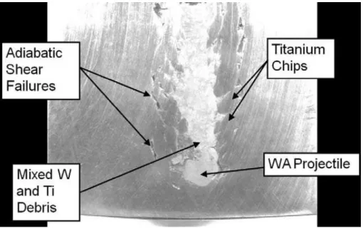
The US army research laboratory considered the use of titanium alloy instead of steels in the defence structures due to its high strength to weight ratio. The impact tests on Ti-6Al-4V alloy plates using a tungsten fragment simulating projectile (FSP) showed failure by adiabatic shear plugging. Fig. 1.5 shows the deep penetration of the tungsten FSP into the titanium plate, see [4].
4
Fig. 1.5 ASB formed in titanium alloy plate allows the deep penetration of tungsten penetrator. After [4].
The ASB+MV are also found to occur in industrial application such as high speed machining (HSM). Contrary to conventional machining, HSM implies high strain rate which triggers the ASBs leading to the formation of serrated chips, see Fig. 1.6. The ASBs appearing on the chip might be a boon in terms of reducing the level of force on the cutting tool and improving chip evacuation [5]. However, the ASBs might also be considered a bane in the high speed cutting process when the serrated chips lead to the fluctuation of the cutting force, decreased tool life, rough surface finish and less accuracy in the machined parts [6].
Fig. 1.6 Shear bands causing serrated chips observed in AISI 1045 steel machined at a cutting velocity of
5
In either case, it is essential to model the ASB+MV phenomena in the numerical simulation of HSM in order to optimize the process.
On the other hand the ASB+MV prove to be useful in certain military applications such as in a kinetic energy (KE) penetrator. A KE penetrator (Fig. 1.8a) also known as a KE weapon uses kinetic energy to penetrate and destroy the targets (Fig. 1.8b).
a b
Fig. 1.7 a) Tungsten KE penetrator design. b) Deployment of Kinetic Energy (KE) penetrator to destroy
targets. After [8].
In KE penetrators made up of ASB susceptible materials such as depleted uranium alloys, on impact, ASBs appear on the planes of maximum shear and fail, causing the outer penetrator material to exit the zone of interaction with the target. The ASBs thus helps in ‘self-sharpening’ and thereby improving the ballistic penetration performance of the penetrator, as seen in Fig. 1.8a, refer [9]. If the KE penetrator is made up of a material resistant to ASB such as tungsten alloy, on impact, the tip of the penetrator will be mushroomed by strain hardening and blunted causing less efficient penetration on target as shown in Fig. 1.8b, refer [9],[10].
6
Fig. 1.8 Illustration of penetration cases and radiographic images of residual penetrators after perforating
armour steel a) U-3/4Ti alloy penetrator: adiabatic shear failure resulting in chiselled nose. b) Tungsten heavy alloy penetrator: mushroomed head. After [11], [9].
The ASB+MV are thus encountered in numerous applications, and it is therefore indispensable to model the combined phenomenon for the design, optimization or ensuring of structural integrity by prediction of the behaviour of the concerned application.
1.2 CONTEXT OF THE STUDY
The goal here is to represent in a unified model the effects of ASB+MV on the representative volume element (RVE). The two global objectives of the present work can be stated as follows:
1. To enrich and improve the embedded-band based constitutive model characterizing ASB induced failure in order to include the effects of micro-voiding in the post-critical regime.
2. Numerically implement the enriched model as user material in a finite element code and evaluate its performance on initial boundary value problems of increasing complexity.
1.2.1 Experiments
The widely referred experimental work producing ASB is the one performed by Marchand and Duffy [12] in which they produced ASB by subjecting HY-100 steel tube to high strain rate torsion. The average stress and strains and the deformation pattern from the applied grid lines obtained are shown in Fig. 1.9. The stages of deformation distinguished from the inclination of the grid lines in the different frames in Fig. 1.9 a,b are as follows:
7
(Stage1) Frame 1 : Homogenous strain distribution
(Stage2) By Frame 4 : Weakly heterogeneous deformation
(Stage3) Frame 5 : Strongly heterogeneous deformation when the ASB initiates
and propagates and causes a progressive drop in strength.
(Stage4) Frame 6 : Crack appearance within the shear band
This experiment demonstrates the significant consequence in the material of the presence of ASB and the subsequent crack supposedly formed by the coalescence of MVs.
The present work does not involve any experimental campaigns. The results of Marchand and Duffy’s experiment are used herein as a reference for numerically calibrating the material constants.
a b
Fig. 1.9 a) Stress-Strain behaviour of HY-100 steel in dynamic shear. b) Photographs of the grid lines
showing deformation pattern at instants of the numbered arrows in (a). After [13].
There are various other experiments evidencing that the premature material failure caused by the ASB is preceded by the formation, growth and coalescence of micro-voids. For example, the microscopic observation by Liu et al. [14] in Fig. 1.10 of the crushed Ti-6Al-4V bars showed ASBs containing voids and coalesced voids (cracks).
8
Fig. 1.10 Micro-voids and coalesced voids (cracks) seen in the wake of ASB in Ti-6Al-4V alloy. After [14].
1.2.2 Modelling
A large scale postulate is adopted herein contrary to the many approaches in the literature describing the ASB. In the present approach, the RVE has a length scale greater than the ASB width; in other words, the shear band is embedded within the RVE.
A physics motivated phenomenological constitutive model was initially developed by Longère et al. [3] in an irreversible thermodynamics framework which described the material degradation induced predominantly by the ASB. The aim here is to use an enriched version of the aforementioned model based on the model developed by Longère and Dragon [15] in order to explicitly reproduce the consequences of micro-voiding in the band wake with a view to clearly distinguish in the post-critical regime the respective contributions to the material softening coming from the two mechanisms namely adiabatic shear banding on one hand and micro-voiding on the other hand. It is important to distinguish the two consecutive mechanisms for the following reasons. The ASB in itself is a weak discontinuity, causing shape change, as there is cohesion of matter within the band, whereas the MV is a strong discontinuity with the absence of matter within, creating irreversible damage in the material and imposing volume change and related hydrostatic components to the induced strain rate because of the void growth. Depending on the loading, the ASB does not necessarily lead to micro-voiding and further failure; and in certain cases, upon unloading, the ASB is quenched by the cooler surrounding material, undergoes phase transformation and finally becomes harder at room temperature than the surrounding matrix material. Therefore considering a unique variable accounting indistinctly for ASB and MV does not allow for
9
distinguishing the zones in the structure where ASB takes place, with potential initial properties recovering after unloading and cooling as explained above, and where irreversible void-growth induced irreversible damage as a precursor to crack formation takes place.
The effects of ASB+MV initiation and evolution on the RVE (material point) response are double: material, namely a progressive anisotropic degradation of the elastic and plastic moduli; and kinematic, namely a progressive deviation of the plastic flow in the band plane. The material effects of ASB and MV are described by anisotropic second order tensor variables. The variables describing the state within the shear bands such as the temperature, strain, strain rate etc. termed as ‘singular’ variables are implicitly embodied within the deterioration variables. The kinematic consequences of ASB and MV are described by supplementary induced inelastic strain rates. As large strains and rotations are involved, objective derivatives are used.
The model also describes the ASB incipience criteria based on a linear perturbation method taking into consideration the role of softening mechanisms namely thermal softening and dynamic recrystallization induced softening. The MV incipience is tentatively treated using a critical value of the local energy release rate.
1.2.3 Numerical simulation
The enriched ASB+MV model is then coded as a user subroutine in Fortran and implemented into the engineering finite element (FE) computation code LS-DYNA. The interest of using this advanced model describing the ASB+MV induced deterioration instead of a simpler engineering oriented model is demonstrated through a comparative study.
For a model to be considered predictive, it has to satisfy a complete Verification and Validation (V&V) procedure. In the V&V procedure, models are tested on initial boundary value problems (IBVP) of increasing complexity against the corresponding experimental results. To begin with, the model is implemented on an RVE scale i.e. on a single FE and the material constants are identified at this scale from the given experiments. Using the constants identified, the model is then implemented on an IBVP with an a priori known path of the ASB+MV. The model’s performance is assessed against experiments and if need be it is recalibrated in a loop with the previous step. The ultimate test of the model’s predictability would be on a complex IBVP where the ASB+MV trajectory is unknown.
10
In the present work, due to the lack of quantitative experimental results concerning the MV, instead of the V&V, the feasibility and robustness of the enriched model is demonstrated on the RVE and structural scale. The implementation of the model on the complex IBVP namely simulation of high speed machining is a work in progress.
1.3 CHALLENGES
The present study poses various challenges in terms of modelling, numerical simulation and conducting experiments which are categorized below as scientific and industrial challenges.
1.3.1 Scientific challenges
It is required to depict as accurately as possible the physics of ASB+MV phenomenon using an advanced three-dimensional model distinguishing the distinct and consecutive mechanisms of adiabatic shear banding and voiding. The post localization micro-voiding needs to be inserted into the basic model of Longère et al., which describes the coupling between plasticity and strain localization, preferably in a ‘unified approach’ without distorting much its formal structure, rather than developing another constitutive model reproducing the coupling between plasticity and ductile damage. Alternative two-dimensional approaches based on variational methods or finite element kinematics enrichment can be found in Longère [16].
Dealing numerically with the local softening phenomenon, resulting from a competition between material hardening and softening mechanisms and which has severe irreversible consequences at the structural level, would be a challenging task. The model has to prove itself to be robust enough to control the evolution of this material instability all along its progress and accordingly overcome the numerical instability the finite element computation code is subject to in the softening regime and subsequent meshing dependence of the numerical results.
The ultimate challenge lies in demonstrating the developed model to satisfy the V&V procedure and thereby proving it to be predictive. The material constants identification in the V&V procedure consequently creates the need for the availability of experimental results. As the deterioration mechanisms of shear banding and micro-voiding are distinguished in the present study, it is required to identify separately the constants pertaining to each of the specific mechanisms. The difficulty in the experimental work lies in identifying the instant of MV incipience during the high strain rate tests.
11
Numerically implementing the model on the complex IBVP of high speed machining in the software LS-DYNA comes with its own set of challenges. It is first required to be able to successfully simulate the machining process using a conventional model after having defined proper boundary and contact conditions. Then the advanced model needs to be implemented overcoming the numerical instability and it has to be able to accurately reproduce the morphology of the chip as examined from experimental results.
1.3.2 Industrial challenges
As stated previously, ASB+MV appear in various industrial and military applications as a boon or a bane.
Titanium is extensively being researched for use in the military platforms for its high ballistic performance when used as an armour and its light-weight to increase mobility or to meet tactical requirements. For example, in Fig. 1.11, by replacing the conventional materials with titanium in the four shown areas on the US military tank, over 1500lbs of combat weight was reduced without the loss of function or protection. The use of titanium as a standalone armour material poses the disadvantage of ASB induced failure.
Fig. 1.11 Titanium weight reduction program for US army battle tank. After [4].
On the other hand, it is desirable to manufacture KE penetrators with materials which fail under shear localization to improve the ballistic penetration. Depleted uranium produces toxic, radioactive dust and debris when it burns through targets and in the interest of post conflict management, the United Nations has passed a resolution
12
banning the manufacture of DU weapons. Therefore, research has to be conducted to replace DU with other materials for efficient KE penetrators.
The study of ASB+MV is essential in the context of high speed machining. HSM experiments at varying cutting velocities in metal alloys susceptible to ASB+MV needs to be carried out to study the effect of ASB+MV on the process so as to obtain the desired accuracy in machining, surface finish and tool life. In order to optimize the HSM process, it is in turn imperative to numerically model the ASB+MV phenomena.
In all the above applications, there is a requisite for accurate numerical simulation of the ASB+MV process, which in turn requires a user defined, physics motivated constitutive model describing initiation and consequences of ASB and MV in the material. From an engineering point of view, the developed model should be feasible to implement on the scale of actual large structures.
In the process of implementing the model on numerical simulation, the industry is also required to carry out experimental campaigns for the purpose of material characterization. An ultimate failure criterion needs to be defined which may vary with each engineering application on which the model is implemented and would also depend on the level of conservativeness imposed on the design. For instance, the presence of ASB may be acceptable whereas the appearance of MV may not be desirable. The developed ASB+MV model is therefore required to be highly reliable and predictive to ensure the integrity of the structures and to augment the performances of weapons and industrial processes.
1.4 ORGANISATION
The chapters are organized in the following manner. Chapter 2 details the physical and mechanical aspects of ASB and MV, the development of the constitutive model and the numerical feasibility and the qualitative analysis of the model on an RVE scale. Chapter 3 presents the numerical implementation of the model on initial boundary value problems. Firstly, the motivation for using the current advanced model describing the ASB induced material deterioration is demonstrated by a comparative study. Then the numerical implementation of the enlarged ASB+MV model on a HSS is assessed followed by the motivations to implement the model on a complex IBVP viz. high speed machining. The conclusions are drawn in Chapter 4 and the prospective work is suggested.
13
1.5 REFERENCES
[1] P. W. Leech, “Observations of Adiabatic Shear Band Formation in 7039 Aluminum
Alloy,” October, vol. 16A, no. October, pp. 1900–1903, 1985.
[2] Q. Xue, M. A. Meyers, and V. F. Nesterenko, “Self-organization of shear bands in titanium and Ti-6Al-4V alloy,” Acta Mater., vol. 50, no. 3, pp. 575–596, 2002.
[3] P. Longère, A. Dragon, H. Trumel, T. De Resseguier, X. Deprince, and E. Petitpas, “Modelling adiabatic shear banding via damage mechanics approach,” Arch. Mech., vol. 55, no. 1, pp. 3–38, 2003.
[4] W. A. Gooch, “The Design and Application of Titanium Alloys to U . S . Army Platforms -2010,” TITANIUM 2010 nternational Titanium Association, no. October. 2010.
[5] A. Molinari, C. Musquar, and G. Sutter, “Adiabatic shear banding in high speed machining of Ti – 6Al – 4V : experiments and modeling,” Int. J. Plast., vol. 18, pp. 443–459, 2002.
[6] S. L. Cai and L. H. Dai, “Suppression of repeated adiabatic shear banding by dynamic large strain extrusion machining,” J. Mech. Phys. Solids, vol. 73, pp. 84– 102, 2014.
[7] C. Z. Duan and L. C. Zhang, “Adiabatic shear banding in AISI 1045 steel during high speed machining: Mechanisms of microstructural evolution,” Mater. Sci. Eng. A, vol. 532, pp. 111–119, 2012.
[8] “Tungsten Alloy Military.” [Online]. Available:
http://directory-tungsten.blogspot.com/2012/08/tungsten-kinetic-energy-penetrator.html.
[9] L. S. Magness Jr., “High strain rate deformation behaviors of kinetic energy penetrator materials during ballistic impact,” Mech. Mater., vol. 17, pp. 147–156, 1994.
[10] J. Liu, L. Shukui, Z. Xiaoqing, Z. Zhaohui, Z. Haiyun, and W. Yingchun, “Adiabatic shear banding in a tungsten heavy alloy processed by hot-hydrostatic extrusion and hot torsion,” Scr. Mater., vol. 59, no. 12, pp. 1271–1274, 2008.
[11] W. S. Andrews, “Depleted Uranium on the battlefield,” Can. Mil. J., pp. 41–46, 2003. [12] A. Marchand and J. Duffy, “An experimental study of the formation process of
adiabatic shear bands in a structural steel,” J. Mech. Phys. Solids, vol. 36, no. 3, pp. 251–283, 1988.
14
[13] K. Cho, S. Lee, S. R. Nutt, and J. Duffy, “Adiabatic Shear Band Formation during Dynamic Torsional Deformation of an HY-100 Steel,” Acta Metall. Mater., vol. 41, no. 3, pp. 923–932, 1993.
[14] X. Liu, C. Tan, J. Zhang, Y. Hu, H. Ma, F. Wang and H. Cai , “Influence of microstructure and strain rate on adiabatic shearing behavior in Ti-6Al-4V alloys,”
Mater. Sci. Eng. A, vol. 501, no. 1–2, pp. 30–36, 2009.
[15] P. Longere and A. Dragon, “Enlarged finite strain modelling incorporating adiabatic shear banding and post-localization microvoiding as shear failure mechanisms,” Int. J. Damage Mech., pp. 1–28, 2016.
[16] P. Longère, “Adiabatic shear banding assisted dynamic failure: Some modeling issues,” Mech. Mater., vol. 116, pp. 49–66, 2018.
15
2
THE PHYSICS MOTIVATED
APPROACH
ABSTRACT
Adiabatic shear banding (ASB) is a dynamic localization phenomenon resulting from thermomechanical instability under high strain rate involving quasi adiabatic conditions and low stress triaxiality loading conditions. High strength steels and lightweight alloys of titanium and aluminium are highly susceptible to this phenomenon which leads to premature material failure. At an advanced stage of the localization process, the adiabatic shear bands have been shown to contain micro-voids which coalesce to form cracks and ultimately lead to the fracture of the structure. A physics-motivated, three dimensional unified constitutive model accounting for the coupled effects of ASB and micro-voiding has been developed in the context of large deformation, high strain rate and high temperature rise. The influence of the softening mechanisms such as thermal softening and DRX induced softening on the ASB onset is also considered here. The enlarged model is herein implemented as user material into the engineering finite element (FE) computation code LS-DYNA in the context of standard FE kinematic formulation and its performances are assessed.
C
ONTENTS2.1 INTRODUCTION ... 17 2.2 PHYSICAL AND MECHANICAL ASPECTS ... 21 2.2.1 PHYSICAL CONSIDERATIONS ... 23
2.2.1.1 Adiabatic shear banding ... 23 2.2.1.2 Micro-voiding in the ASB wake ... 24 2.2.1.3 Ultimate rupture ... 25 2.2.2 MECHANICAL CONSEQUENCES ... 26
2.2.2.1 Preliminaries ... 26 2.2.2.2 Adiabatic shear banding ... 27 2.2.2.3 Micro-voiding ... 31 2.2.2.4 Combined effects of ASB and Micro-voiding ... 33 2.3 CONSTITUTIVE MODELLING ... 35 2.3.1 LARGE ANISOTROPIC STRAIN FRAMEWORK ... 36
2.3.2 THERMODYNAMIC FRAMEWORK ... 38
2.3.3 CONSTITUTIVE EQUATIONS ... 39
16
2.3.3.2 State potential ... 43 2.3.3.3 Constitutive state laws ... 44 2.3.3.4 Yield function ... 45 2.3.3.5 Equivalent stress ... 45 2.3.3.6 Viscoplastic and viscous-damage potential ... 48 2.3.3.7 Evolution laws ... 48 2.3.3.8 Viscous stress ... 49 2.3.3.9 Temperature rise ... 50 2.4 DETERIORATION INCIPIENCE CRITERIA ... 50 2.4.1 ASSUMPTION OF ADIABATIC CONDITIONS ... 50
2.4.2 SOFTENING MECHANISMS TRIGGERING THE ASB FORMATION ... 51
2.4.2.1 Thermal softening ... 51 2.4.2.2 Dynamic recrystallization ... 52 2.4.3 MECHANISMS TRIGGERING THE MV FORMATION ... 54
2.5 NUMERICAL IMPLEMENTATION ... 56 2.5.1 NUMERICAL ISSUES ... 56
2.5.1.1 Regularization and mesh dependence ... 57 2.5.1.2 Sampling of the time increment ... 57 2.5.1.3 Band orientation ... 58 2.5.1.4 Stress triaxiality ... 58 2.5.1.5 Crack formation ... 58 2.5.2 ASB+MV MODEL IMPLEMENTATION ON RVE SCALE ... 59
2.5.2.1 High strength steel: Thermal softening-controlled ASB onset ... 59 2.5.2.2 High strength titanium alloy: Influence of dynamic recrystallization ... 63 2.6 CONCLUSION ... 65 2.7 REFERENCES ... 66
17
2.1 INTRODUCTION
Adiabatic shear banding is a distinct deformation mechanism which occurs in viscoplastic solids during high strain rate and impact loading acting as a precursor to failure such as plugging failure, ductile fracture, explosive failure, etc., see [1],[2],[3]. The Adiabatic Shear Bands (ASB) are seen typically in high strength metals and alloys such as steels and titanium and aluminium alloys (as well as in some glassy polymers) which are often used as component materials for aircraft and other structures. The ASBs are undesirable when they cause catastrophic failures of structures such as protection plates for ballistic applications [4] involving military or civil threats (missile, bird strike, etc). On the other hand, they are desirable in military application such as kinetic energy penetrators in which the formation of ASBs on the side ends of the penetrator helps in a self-sharpening-like mechanism ([5],[6],[7]). They also find application in high speed machining in which they have mitigated effect in the sense that they help to reduce the cutting force but at the expense of cutting force oscillation and rougher surface finish [8],[9]. In the context of engineering design, it is thus crucial to be able to numerically reproduce the consequences of this phenomenon.
The ASBs are narrow regions of intense plastic shear deformation and strength softening resulting from thermo-mechanical instability induced by a competition between hardening and softening mechanisms in the regions of low stress triaxiality during high strain rate loading. The mechanisms causing the softening which triggers the ASB formation are mostly plastic dissipation-induced temperature rise and possibly dynamic recrystallization (DRX) in certain materials. The ASBs appear, for example, in AA7075 aluminium alloy cylinders under compression loading (Fig. 2.1a) when loaded at a strain rate of 2500/s in the form of an ‘X’ in the cross section of the specimen (Fig. 2.1b) (Courtesy Manar and Longère). The shear bands are distinctly oriented causing local degradation of the material properties and a form of induced anisotropy at the scale of the specimen.
As stated by Bai and Dodd [10], a metal alloy exhibiting excellent mechanical properties in terms of strength, toughness and weight may possess a severe weakness in terms of its susceptibility to the adiabatic shear banding. The latter is a complex mechanism requiring a careful consideration of the variables playing a role in the formation and propagation of the shear bands. The consequence of the presence of ASB is shown, for example, in the experiment performed by Marchand and Duffy [11]. A thin-walled tubular steel specimen (Fig. 2.2 a) was subjected to high strain rate torsion by means of torsional Kolsky bar. The deformation pattern (Fig. 2.2 b), the average stress and strain (Fig. 2.2 c) were inferred. By combining (Fig. 2.2 b) and (Fig. 2.2 c), three stages of deformation were distinguished: the 1st stage showed homogenous strain distribution,
18
the 2nd stage is a weakly heterogeneous deformation and the 3rd stage is a strongly
heterogeneous deformation when the ASB initiates and propagates and causes a progressive drop in strength of the material leading to premature structural failure.
a b
Fig. 2.1 AA7175 aluminium alloy a) Undeformed cylindrical specimen b) Cross-section of the specimen
after high strain rate compression loading under microscope showing ASB. Courtesy of Manar and Longère (2018).
In the literature, many approaches describing the ASB degradation have been proposed at a scale lower than the bandwidth implying the use of a very fine meshing, where the mesh size is smaller than the band width, during finite element analysis; see e.g. Peirs et al. [12], Bonnet-Lebouvier et al. [13]and Teng et al. [14]. Yet, knowing that the ASB width is of the order of some tens or hundreds of micrometers, such an approach is not suitable for structures of large dimensions (an aircraft and even a part of an aircraft) requiring coarse meshing, and on the other hand the material within the band is generally different from the one outside as the former may have undergone significant transformations even though material in the band remains in a solid state. With the aim of reproducing the ASB-induced failure in large structures, Longère et al. [15] developed a three-dimensional phenomenological model in a large scale postulate approach in which the representative volume element (RVE) has a length scale greater than the width of the ASB amounting to a global insight into the material response, see Fig. 2.3. The effects of ASB initiation and evolution on the RVE (material point) response are double: kinematic, namely a progressive deviation of the plastic flow in the band plane, and material, namely a progressive anisotropic degradation of the elastic and plastic moduli. The performances of the ASB-model have been assessed considering the dynamic shearing of a hat-shaped structure, see [16] then a ballistic problem, see [4]. Large scale approaches based on variational methods and enriched finite elements can be found in [17] and [18],[19] and a review of ASB-oriented modelling approaches in [20].
19 a b Stage 1 Homogeneous deformation Stage 2 Weakly heterogeneous deformation Stage 3 Strongly heterogeneous deformation Shear Bands c
Fig. 2.2 After [11] a) Torsional specimen b) Deformation stages observed by means of grid lines c) Shear
stress-shear strain curve obtained during experiment.
Once the ASB is formed, the softer material within the band serves as a site for the nucleation and growth of micro-voids. These micro-voids additionally contribute to softening mechanism and accelerate the post-localization drop in strength of the RVE in the large scale postulate framework. The micro-voids coalesce and lead to the formation of cracks which ultimately fracture the material. The evidence of the presence of micro-voids within the ASB was shown by various experimental observations ([21],[2],[22]). Longère and Dragon [23] , for example, carried out experiments on shear compression specimens (SCS) (see Fig. 2.4a) dimensioned to allow for generating a local shear loading under a global compression loading. The observation of the fractured surface of the SCS (see Fig. 2.4 b, c) showed elongated dimples as the result of micro-voiding in the wake of the ASB. It is clearly seen that the fracture occurred due to two successive mechanisms: adiabatic shear banding and then micro-voiding.
20
Fig. 2.3 Scale postulate concept. After [20]. Up: Body crossed by a shear band. Bottom left: small scale
postulate: the RVE length scale h is lower than the bandwidth w. Bottom right: large scale postulate: the RVE length scale h is greater than the bandwidth w.
a b c
Fig. 2.4 After [23] (a) Shear compression specimen; Microscopic observation of fractured surface (b) 3D
view showing ASB; (c) Detailed 3D view showing elongated dimples in the band plane
The constitutive model developed by Longère et al. [15] reproduced the material degradation induced predominantly by the ASB. The aim here is to enrich the aforementioned ASB-model in the post-localization regime in order to reproduce explicitly the consequences of micro-voiding (MV) in the band wake and thereby to be
21
able to clearly distinguish in the post-critical regime the respective contributions to the material softening coming from the two mechanisms namely adiabatic shear banding on one hand and micro-voiding on the other hand. Indeed the ASB does not necessarily lead to micro-voiding and further failure, and in this case, when unloaded, the ASB-containing material may recover properties close to its initial ones. On the other hand, considering a unique variable accounting indistinctly for ASB and MV does not allow for distinguishing the zones in the structure where ASB takes place, with potential initial properties recovering after unloading and cooling as explained above, and where irreversible void-growth induced damage as a precursor to crack formation takes place. An initial enriched model including MV is proposed in [24]. The original enlarged (ASB+MV)-model is revisited herein, see also [25], and modified in order to represent some operating physical mechanisms. The modified model is then implemented as user material into the engineering finite element (FE) computation code LS-DYNA in the context of standard FE kinematic formulation. The numerical feasibility on a simple finite element and a parametric study of the model are conducted here.
In Section 2.2, the physics and the mechanical aspects of the phenomena of adiabatic shear banding and micro-voiding and their consequences are discussed. A general framework of modelling these mechanisms is also laid out. The more specific constitutive model is detailed in Section 2.3 along with deterioration incipience criteria in Section 2.4. The numerical issues encountered in the finite element implementation and performance of enriched ASB+MV model by numerical implementation on RVE scale are shown in Section 2.5. Finally the conclusions are drawn in Section 2.6.
2.2 PHYSICAL AND MECHANICAL ASPECTS
Considering the various stages leading up to the rupture, the materials accommodate the deformation in different ways. Some possible deformation accommodation paths are illustrated in Fig. 2.5. A material exhibits elasticity during initial loading after which it may either pass into elasto-plasticity or directly into damage stage leading to rupture depending on whether it is ductile or brittle. For ductile materials, further loading may lead either to diffused damage or localised elasto-plasticity. The diffused damage and the localised elasto-plasticity bring about the ultimate rupture of the material.
22
Fig. 2.5 Typical ways for a material to accommodate the deformation
Standard ductile materials follow the black arrow path as shown in Fig. 2.5 in which the diffused and localised damage is preceded by elasto-plasticity. Geomaterials (concrete, ceramics, etc) for example, generally follow the blue arrow deformation path. When loaded well below the glass transition temperature Tg, polymers show also a (quasi)
brittle behaviour. When loaded around Tg, the polymers exhibit a viscoelastic behaviour.
The formation of ASB takes place following the steps of the red arrows. The high strength metals and alloys under high strain rate loading first exhibit elasto-plasticity. During this stage, the self-heating caused by plastic dissipation and/or softening due to dynamic recrystallization lead to the formation of a localized shear deformation (ASB) which causes material strength deterioration and alters the kinematics of the plastic flow. Further, damage is encountered within the shear bands causing the material failure.
The scenario for ASB- and MV-assisted failure (path following red arrow in Fig. 2.5) is depicted in Fig. 2.6. The regular mechanism of polycrystalline plasticity is in action during the initial stage of hardening. Then the formation of the ASB reduces the material strength. The drop in the material strength in the post critical stage is potentially accelerated by the formation of micro-voids in the wake of the ASB. The micro-voids coalesce and ultimately rupture the material.
Elasticity Elasto- Plasticity Diffused Damage Elasto- Plasticity + Diffused Damage Localised Damage Localised Elasto- Plasticity Localised Elasto- Plasticity + Damage ACCOMMODATION OF DEFORMATION Localised Damage
Fail
ur
e
23
Polycrystalline Plasticity (PP)
Adiabatic Shear Band
(ASB) Micro-voids (MV) Rupture
Fig. 2.6 After [11],[2]. Successive mechanisms acting during ASB induced deterioration.
In the following subsections, the salient physical and mechanical features involved are presented.
2.2.1 Physical considerations
The physical features and the formation process of the adiabatic shear bands and micro-voids are presented in this section.
2.2.1.1 Adiabatic shear banding
As mentioned above, the ASBs are distinctly oriented shear localizations resulting from a thermo-mechanical instability phenomenon. The heat produced from the plastic deformation during high strain rate loading, when not having enough time to be conducted away leads to local increase in temperature giving rise to a ‘quasi-adiabatic’ condition. This causes a local thermal softening of the material. Thermo-mechanical instability comes into play as a competition arises between the thermal softening and strain or/and strain-rate hardening. When the rate of this thermal softening surpasses the strain/strain rate hardening, the material deformation becomes unstable and concentrates in narrow softened bands which are termed as ASBs. This widely accepted
24
mechanism of ASB inception and growth was first proposed by Zener and Hollomon [26].
In some cases, for example in steel, the ASBs exhibit phase transformation due to high temperature within the band (>1200K) and appear as distinct white bands after being quenched once unloaded as seen in Fig. 2.7. The shear band width usually ranges between 10-100μm as stated in [10].
Fig. 2.7 Evidence of phase transformed ASB in steel. After [22].
2.2.1.2 Micro-voiding in the ASB wake
Although the ASBs occur in conditions of negative or nil stress triaxiality, micro-voids have been observed to form and grow within the bands. The micro-voiding could be initiated in the band wake by the hydrostatic tension when there is a change in the loading path. Or as stated in [20], when the loading is interrupted after the formation of the ASB, the quenching of the hot band by the surrounding bulk material may lead to phase transformation involving possible volume increase (as for martensitic transformation) and strain incompatibility-induced crack formation at the band/matrix interface. However, the ASB induced failure is generally observed under monotonic loading. For example, a thick wall cylinder implosion technique was carried out by Xue et al. [2] to produce shear bands on Ti-6Al-4V alloys. The microscopic observation of the ASB showed spherical void nucleation (Fig. 2.8a). The spherical voids were later seen to elongate to ellipse shape rotate along the direction of the shear momentum (Fig. 2.8b). Impact tests on hat shaped specimen by Peirs et al. [1] showed micro-cracks in the wake of the ASB oriented along the highly deformed grains which is different from the ASB orientation Fig. 2.8c.
25
a b c
Fig. 2.8 Microscopic observation of ASB showing a) Spherical void nucleation. b) Elongated micro-voids at
a later stage. After [2]. c) Micro-cracks observed within the ASB. After [1]
Various perspectives on the stress triaxiality condition for the formation of micro-voids have been proposed which is discussed in section 2.5.1.4. Under a global shear pressure loading, Longère et al. [27] demonstrated that micro-voids can initiate and grow around inclusions in the material. Another theory cited by Odeshi et al. [22] is that the opening of the voids could be because of the high singular temperatures within the ASB causing atomic mobility or creating a lower flow stress in the ASB than the surrounding regular material thereby generating a local tensile stress.
2.2.1.3 Ultimate rupture
The ASB by itself is not a failure mode i.e. a strong discontinuity but it acts as a precursor to premature material failure. It can be seen clearly in the Kalthoff -Winkler (KW) impact test performed by Roux et al. [28] on armour steel that the ASB serves as a path for the crack propagation as shown in Fig. 2.9.
a b
Fig. 2.9 After [28]. a) KW-type impact test configuration. b) Observation of ASB as a precursor to crack.
ASB
26
The micro-voids which germinate within the ASB coalesce to the formation of cracks leading to the ultimate rupture of the material. Liu et al. [29] performed dynamic compression on Ti6Al4V alloy cylinders leading to ASB induced failure. The microscopic observation of the crushed specimens showed ASBs containing voids and coalesced voids (cracks) as shown in Fig. 2.10a. Likewise the observation of the fractures surface of Rittel-Lee-Ravichandran-type shear compression specimens (SCS-RLR) by Longère and Dragon [23], showed the evidence of micro-voids in the ASB wake, see Fig. 2.10b.
a b
Fig. 2.10 Micro-voids observed in the ASB wake after dynamic compression loading on a) Ti6Al4V
cylinders (After [29]) b) SCS-RLR (After [23])
2.2.2 Mechanical consequences
While modelling of ASB can be widely found in the literature, the subsequent mechanism of micro-voiding and its modelling as a distinct contribution to the failure process is largely overlooked. The present work aims to model in a unified approach the ASB and subsequent MV induced degradation.
2.2.2.1 Preliminaries
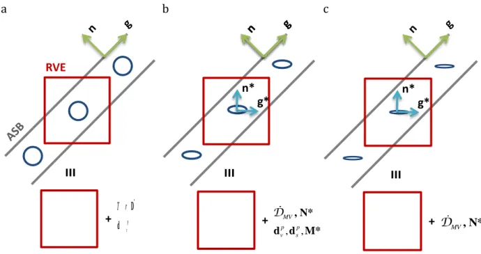
According to the large scale postulate, see Fig. 2.3 and Fig. 2.11, the shear band or the shear band cluster is considered as an entity embedded within the RVE. The vector g is
collinear to the slip direction in the band plane and n represents the normal to the band
plane. Accordingly, the structural tensors used in the following are defined in (2.1) where ()S represents the symmetric and ()AS the skew-symmetric parts of the tensor.
According to experimental evidences, the ASBs develop along the planes of maximum shear stress within the RVE and thus their orientations are calculated.
27 ( ) ( ) N = n n M = g n T = g n S AS (2.1)
Fig. 2.11 ASB orientation vectors
2.2.2.2 Adiabatic shear banding
ASBs are not a type of crack or a conventional ‘damage’ as there is cohesion of matter within the bands and without any surface separation. Neither are they slip bands which occur under quasi static conditions as the physics of the phenomenon is different. What is observed is a large gradient of the shear strain between the matrix and the band. It is considered here as a ‘degradation’ mechanism as it degrades the mechanical properties of the overall material/structure in which it is present.
ASBs are therefore classified as ‘weak’ discontinuity which involves a discontinuity of the gradient of the displacement/velocity i.e. of the strain/strain rate field. A ‘strong’ discontinuity such as a crack on the other hand involves a discontinuity of the displacement/velocity field. The concept of discontinuity is illustrated in Fig. 2.12.
n g
28
Fig. 2.12 Displacement and strain fields in different cases of discontinuity.After [20]
Material consequences
As the shear band is strongly oriented in space, it anisotropically degrades the elastic and plastic material properties of the RVE containing the band based on its orientation. The degradation induced by the ASB may therefore be defined by a 2nd order tensor
variable D definedin (2.2). The components of D are: the scalar degradation intensity
denoted by D and the orientation tensor N of the ASB.
ij ij
D DN (2.2)
Consider the illustration in Fig. 2.13, the normal to the ASB is in direction 2, in which case, the deterioration tensor is calculated below:
29
Fig. 2.13 Illustration ASB orientation normal to the 2 direction.
0 0 0 0 0 0 0 1 1 0 1 0 0 0 0 n N D sym sym D (2.3)
According to Fig. 2.13, the RVE can be viewed as a 3-layer material or sandwich material with 1 thin soft layer inserted between 2 thick hard layers, inducing a form of orthotropy. The resulting elastic shear modulus 12 and elastic axial (Young’s) modulus
22
E are accordingly expected to progressively vanish while the other elastic moduli are
not or less affected.
12 0 12 12 12 12 12 22 0 22 22 22 22 22 2with ASB ASBc ASB ASBc
ASB ASBc ASB ASBc
ASB c ASB c e ASB e ASB c ASB c ASB e E E E E e D D D D D D D D D D D D D D (2.4)
where τ is the elastic Kirchhoff stress tensor,
0, E0
and
c,Ec
are the initial andcritical, elastic shear and axial (Young’s) moduli. Note that
c,Ec
have non zero valuessince ASB preserves matter cohesion. If we want to make an analogy with the (1-D)-approach [30], D evolving between 0 (sound) and 1 (failed), we should have
12 0 22 0 1 1 ASB ASB ASB ASB b E a E D D D D (2.5)with D being authorized to have (i) different instantaneous effects on ASB 12 and E22
through the constants
a b, and (ii) a critical value lower than 1.2 1 3
ASB
30
Kinematic consequences
The kinematic consequences of the presence of the shear band are viewed as those of a ‘macro-dislocation’ considering an RVE as illustrated in Fig. 2.14.
Fig. 2.14 ASB viewed as a super dislocation and the equivalent RVE with kinematic consequences.
The velocity gradient created by the regular plastic deformation outside the band is designated as Lp. The ASB induces a supplementary velocity gradient LASB as a result of
glide velocity ASB in the direction of the unit vector
g. L L L L g n in p ASB ASB ASB (2.6)
The deterioration-induced velocity gradient LASB for a given band pattern is
partitioned into symmetric and skew-symmetric parts leading to the corresponding strain rate dASBand spin ωASB respectively as given below.
, , , ; ASB ASB ij ij ASB ASB ij i j ASB ASB ij ij d M L g n T
(2.7)The introduction of LASB facilitates the smoothening of the boundary discontinuity
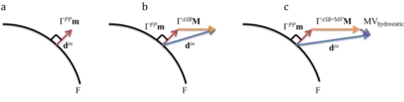
caused by ASB as it is done in crystalline plasticity, see Fig. 2.14. The kinematic consequence of the presence of ASB is thus shown by the total inelastic strain rate din
resulting from the superposition of regular plastic strain rate ( )
din PP by the singular
strain rate induced by ASB ( )
din ASB . ( ) ( ) in in PP in ASB ij ij ij d d d (2.8)

![Fig. 1.11 Titanium weight reduction program for US army battle tank. After [4].](https://thumb-eu.123doks.com/thumbv2/123doknet/11497048.293386/26.892.109.775.607.965/fig-titanium-weight-reduction-program-army-battle-tank.webp)
![Fig. 2.2 After [11] a) Torsional specimen b) Deformation stages observed by means of grid lines c) Shear stress-shear strain curve obtained during experiment](https://thumb-eu.123doks.com/thumbv2/123doknet/11497048.293386/34.892.107.789.105.718/torsional-specimen-deformation-stages-observed-shear-obtained-experiment.webp)
![Fig. 2.4 After [23] (a) Shear compression specimen; Microscopic observation of fractured surface (b) 3D view showing ASB; (c) Detailed 3D view showing elongated dimples in the band plane](https://thumb-eu.123doks.com/thumbv2/123doknet/11497048.293386/35.892.117.798.620.974/compression-specimen-microscopic-observation-fractured-surface-detailed-elongated.webp)

![Fig. 2.12 Displacement and strain fields in different cases of discontinuity. After [20]](https://thumb-eu.123doks.com/thumbv2/123doknet/11497048.293386/43.892.200.693.110.543/fig-displacement-strain-fields-different-cases-discontinuity.webp)
![Fig. 2.22 After [31]. Influence of DRC-DRX related constants on strain hardening.](https://thumb-eu.123doks.com/thumbv2/123doknet/11497048.293386/69.892.230.664.106.393/fig-influence-drc-drx-related-constants-strain-hardening.webp)
