ÉCOLE DE TECHNOLOGIE SUPÉRIEURE UNIVERSITÉ DU QUÉBEC
THESIS PRESENTED TO
ÉCOLE DE TECHNOLOGIE SUPÉRIEURE
IN PARTIAL FULFILLMENT OF THE REQUIREMENTS FOR MASTER’S DEGREE IN MECHANICAL ENGINEERING
M. Eng.
BY Alireza JALALI
PERFORMANCE OF MINIMUM QUANTITY COOLING (MQC) WHEN TURNING ALUMINUM ALLOY 6061-T6: SURFACE ROUGHNESS,
TOOL TEMPERATURE AND AEROSOL EMISSION
MONTREAL, 22 JULY, 2013 © Copyright 2013 reserved by Alireza JALALI
© Copyright reserved
It is forbidden to reproduce, save or share the content of this document either in whole or in parts. The reader who wishes to print or save this document on any media must first get the permission of the author.
BOARD OF EXAMINERS
THIS THESIS HAS BEEN EVALUATED BY THE FOLLOWING BOARD OF EXAMINERS
Pr. Victor Songmene, Member & Thesis director
Mechanical Engineering Department at École de technologie supérieure (ÉTS)
Pr. Patrick Hendrick, Member & Thesis Co-director
Aero-Thermo-Mechanics Department at Université Libre de Bruxelles (ULB)
Pr. Souheil-Antoine Tahan, President of the Board of Examiners
Mechanical Engineering Department at École de technologie supérieure
Pr. Balazinski Marek, Member of the jury
Mechanical Engineering Department at École Polytechnique de Montréal
THIS THESIS WAS PRENSENTED AND DEFENDED
IN THE PRESENCE OF A BOARD OF EXAMINERS AND PUBLIC ON 12 JUNE, 2013
ACKNOWLEDGMENT
Firstly, I would like to thank my director, Dr. Victor Songmene, professor of Mechanical Engineering Department at ÉTS and my co-director, Dr. Patrick Hendrick, professor of Aero-Thermo-Mechanics Department at ULB for their confidence on me and offering the required and well received leadership as well as providing necessary logistics and equipment that enabled me to succeed in my research project.
I would also like to thank to Dr. Patrick Hendrick, who gave me the opportunity to gain a world of experience out of my international internship in Brussels.
My grateful thanks are extended to the "Aluminum Research Centre" (REGAL), "Fond de la Recherche du Quebec sur la Nature et les Technologie" (FRQNT) and the International Relations Office of the ÉTS for providing financial supports.
I would like to express my gratitude to all the people at the Laboratoire d’ingénierie des produits, procédés et systèmes (LIPPS) at École de Technologie Superieure (ÉTS) and the Aero-Thermo-Mechanics Department at Université Libre de Bruxelles (ULB) and also the System Tecnolub sa., for their assistance in different parts of this research work.
Special thanks to Doctor Seyed Ali Niknam, who as a good friend, was always willing to help and give his best suggestions.
I lovingly dedicate this thesis to my adorable spouse, Atefeh, for her love, remarkable patience and continued support during my M.Sc. study at ÉTS.
This Master program accompanied by the international internship in Belgium and its success for me was a proof of the value of an efficient team work and environment and gave me a taste of real-world challenges that I will be facing in my future academic and professional endeavours.
PERFORMANCE OF MINIMUM QUANTITY COOLING (MQC) WHEN TURNING ALUMINUM ALLOY 6061-T6: SURFACE ROUGHNESS,
TOOL TEMPERATURE AND AEROSOL EMISSION Alireza JALALI
ABSTRACT
Nowadays industries desire to obtain parts with better accuracy (dimensional and form) and surface finish at low cost. These factors (accuracy, cost and productivity) are used to evaluate the performance of machining processes. When material removal rate increases, the higher tool temperature is anticipated and therefore, better cooling is required.
To reduce the heat effects on cutting tools and therefore improve the life, an efficient and cost effective application of the cutting fluid is required. Also, to cope with environmental and occupational safety issues, new cooling and lubricating methods such as minimum quantity lubrication (MQL) and minimum quantity cooling (MQC) have been proposed.
The use of near dry or minimum quantity cooling lubrication (MQCL) considerably decreases cutting fluid consumption as compared to conventional flood cooling and it increases the machinability when compared with dry machining. The surface roughness, heat generation in cutting tool, generated dust and aerosol emission can be known as machining quality index which are highly influenced by cutting conditions.
The presented research work investigates the effects of lubrication mode (dry, wet and MQC) and cutting conditions (feed rate, cutting speed, air and liquid flow rates) on surface roughness, cutting tool temperature, aerosol and dust emission during turning of aluminum alloy 6061-T6. It is found that there are optimum conditions for which MQC machining leads to better surface finish than flood and dry machining; MQC and wet machining produce more aerosols (liquid and solid) as compared to dry machining; and finally, MQC produces less
PERFORMANCE OF MINIMUM QUANTITY COOLING (MQC) WHEN TURNING ALUMINUM ALLOY 6061-T6: SURFACE ROUGHNESS,
TOOL TEMPERATURE AND AEROSOL EMISSION
Alireza JALALI RÉSUMÉ
Aujourd'hui, les industries désirent réaliser la meilleure finition de surface et un taux élevé d'usinage. Ces facteurs sont utilisés pour évaluer la performance des processus d'usinage. Lorsque le taux d'enlèvement de matière augmente lors de l'usinage, la température de l'outil s’élève aussi et le refroidissement devient nécessaire.
Pour réduire les effets de la chaleur sur les outils de coupe et la durée de vie des machines, une application efficace et rentable du fluide de coupe est nécessaire. En outre, pour faire face aux questions environnementales et de sécurité au travail, les nouvelles méthodes de lubrification et de refroidissement telles que la quantité minimale de lubrifiant (MQL) et la quantité minimale de refroidisseur (MQC) ont été proposées.
L'usinage presque sec ou microlubrifiée avec la quantité minimale de refroidisseur ou de lubrifiant (MQCL), fournit une diminution considérable de la consommation de fluide de coupe par rapport à un refroidissement conventionnel ainsi que l'augmentation de l'usinabilité en comparaison avec d'usinage complètement à sec. La rugosité de surface, la réduction de la chaleur générée dans l'outil de coupe et l'émission de la poussière et d'aérosols dans l'atelier, comme un indicateur de la qualité du processus d'usinage, dépendent largement des conditions d'usinage.
La présente recherche sorte sur l'étude des effets des différentes conditions de coupe, en utilisant de la quantité minimale de refroidisseur, sur la rugosité de surface, la température de l'outil de coupe et la concentration des aérosols et des poussières lors du tournage d'alliage d'aluminium 6061-T6. Les résultats sont comparés a ceux obtenus en tournage à sec et ceux
Mots-clés: tournage, aluminum, condition optimale, MQC, injecteur d’airblast, débit de l’air et de l’huile
TABLE OF CONTENTS Page
INTRODUCTION ...1
CHAPTER 1 LITERATURE REVIEW ...5
1.1 Introduction ...5
1.2 Turning ...5
1.3 Machining lubrication modes ...6
1.3.1 Wet ... 7 1.3.2 Dry ... 8 1.3.3 Semi-Dry ... 8 1.3.4 Properties of lubricant ... 9 1.4 Atomization...10 1.4.1 Definition ... 10 1.4.2 Mechanism of atomization ... 11
1.4.3 Theoretical and experimental studies (Theories) ... 12
1.4.4 Atomization Summary ... 14
1.5 Atomizers and pulverization ...14
1.5.1 Introduction ... 14
1.5.2 Different lubrication systems ... 15
1.5.3 Nozzle performance properties ... 20
1.5.4 Different types of atomizers ... 21
1.5.5 Common features of different twin-fluid atomizers ... 34
1.6 Prediction of mean drop size and drop size distribution ...34
1.6.1 Introduction ... 34
1.6.2 Definition ... 35
1.6.3 The empirical correlations related on the mean drop diameter ... 37
1.6.4 The effects of variables on mean drop size ... 45
1.7 Cutting parameter effects on machining quality characteristics ...48
1.7.1 Cutting parameter effects on Surface Roughness ... 48
1.7.2 Cutting parameter effects on cutting tool temperature ... 49
1.7.3 Cutting parameter effects on aerosol emission ... 51
1.8 Conclusion of literature review and refining of problematic ...58
CHAPTER 2 INSTRUMENTS AND EXPERIMENTAL PROCEDURES ...61
2.1 Introduction ...61
2.2 Instruments ...61
2.2.1 Injectors... 61
2.2.2 Laser diffraction system ... 64
2.2.3 Pumps (GLS, SLS1.2-2 and DDA pumps) and flow sensor ... 65
2.2.4 TSI 8532 DustTrak – II aerosol monitor ... 71
2.2.5 Profilometer ... 72
3.3 Effects of atomizer length ...89
3.3.1 Sauter mean diameter (SMD) ... 89
3.3.2 Injection angle ... 91
3.4 Effects of liquid orifice shape ...93
3.4.1 Sauter mean diameter (SMD) ... 94
3.4.2 Injection angle ... 96
3.5 Atomizer geometry effects on SMD and injection angles when using continuous pump and high liquid flow rates ...100
3.5.1 Liquid orifice diameter effects ... 100
3.5.2 Atomizer length effects ... 102
3.5.3 Liquid orifice shape effects ... 104
3.6 Validation of the Sauter mean diameter (SMD) experimental results ...107
3.7 Conclusion ...110
CHAPTER 4 MACHINING PERFORMANCE WHEN TURNING AA6061-T6 WITH PULSED AND CONTINUOUS COOLING/LUBRICATION ...111
4.1 Introduction ...111
4.2 Surface roughness investigation using the pulsed and continuous pumps when turning aluminum alloy 6061-T6 ...111
4.2.1 Introduction ... 111
4.2.2 Effect of cutting parameters on surface roughness when using pulsed pump ... 112
4.2.3 Effect of cutting parameters on surface roughness when using continuous pump ... 115
4.3 Cutting tool temperature and dust concentration investigation using the continuous pumps when turning of aa6061-t6 ...122
4.3.1 Introduction ... 122
4.3.2 Effect of cutting parameters on tool temperature ... 123
4.3.3 Effect of cutting parameters on dust concentration (Dc) ... 131
4.4 Multiple response optimization of machining ...139
4.4.1 Introduction ... 139
4.4.2 Desirability Function ... 139
CONCLUSION ...145
APPENDIX 1 ...151 APPENDIX 2 ...157 BIBLIOGRAPHY ...163
LIST OF TABLES
Page
Table 1.1 Applications of MQL & dry machining (DGUV, 2010) ...9
Table 1.2 The comparison between metering pump and pressure tank (Unfallversicherung, 2010) ...19
Table 1.3 Definitions and descriptions of mean particle diameter (Lee Black, McQuay and Bonin, 1996) ...36
Table 1.4 The parameters used in Kim and Marshall drop size measurements (Lefebvre, 1980) ...40
Table 1.5 The parameters used in Weiss and Worsham drop size measurements (Lefebvre, 1980) ...43
Table 1.6 The effects of the different variables on mean drop size (Lefebvre, 1980) ...46
Table 1.7 Dust generation when using different cutting conditions and chip morphologies (Khettabi, Songmene and Masounave, 2010) ...55
Table 2.1 Dimensions of atomizers...63
Table 2.2 EMULTEC VG specifications ...64
Table 2.3 Mecagreen-550 specifications (CONDAT Lubrifiants) ...64
Table 2.4 Adjustment of Microlubrication systems ...67
Table 2.5 DDA reference specifications (GRUNDFOS, November 2010) ...69
Table 2.6 Flow sensor reference specifications (Manual, Aug 2012) ...70
Table 2.7 Gas and Liquid flow rates ...74
Table 2.8 Cutting parameters (Experiments using DDA pump) ...76
Table 2.9 Cutting parameters (Experiments using SLS1.2-2 pump) ...77
Table 3.1 Dimensions of the atomizers ...79
Table 3.7 Percentage contribution of parameters affecting injection angle ...85 Table 3.8 Examples of the measured injection angle ...88 Table 3.9 The ANOVA table of SMD when using nozzles with different lengths
and GLS pump ...89 Table 3.10 The ANOVA table of SMD when using nozzles with different lengths
and DDA pump ...90 Table 3.11 The ANOVA table of injection angle when using nozzles with different
lengths and GLS pump ...91 Table 3.12 The ANOVA table of injection angle when using nozzles with different
lengths and DDA pump ...92 Table 3.13 Liquid orifice shapes ...94 Table 3.14 The ANOVA table of SMD when using nozzles with different orifice
shapes and GLS pump ...95 Table 3.15 The ANOVA table of SMD when using nozzles with different orifice
shapes and DDA pump ...95 Table 3.16 The ANOVA table of injection angle when using nozzles with
different orifice shapes and GLS pump ...97 Table 3.17 The ANOVA table of injection angle when using nozzles with
different orifice shapes and DDA pump ...98 Table 3.18 Gas and liquid flow rates ...100 Table 3.19 The ANOVA table of SMD when using nozzles with different liquid
Table 3.20 The ANOVA table of injection angle when using nozzles with
different liquid orifice diameter and DDA pump ...101
Table 3.21 The ANOVA table of SMD when using nozzles with different lengths and DDA pump ...103
Table 3.22 The ANOVA table of injection angle when using nozzles with different lengths and DDA pump ...103
Table 3.23 The ANOVA table of SMD when using nozzles with different liquid orifice shapes and DDA ...105
Table 3.24 The ANOVA table of injection angle when using nozzles with different liquid orifice shapes and DDA ...105
Table 3.25 Initial conditions of the experimental and theoretical studies ...109
Table 3.26 Experimental air/liquid mass ratio ...110
Table 4.1 The ANOVA table of surface roughness when using pulsed pump ...114
Table 4.2 The ANOVA table of surface roughness when using Lg20.0dl0.25 ...119
Table 4.3 The ANOVA table of surface roughness when using Lg33.5dl1.00 ...120
Table 4.4 The ANOVA table of cutting tool temperature when using Lg20.0dl0.25 ...127
Table 4.5 The ANOVA table of cutting tool temperature when using Lg33.5dl1.00 ...128
Table 4.6 Quality responses statistical results ...141
Table 4.7 Optimum setting level when using Lg20.0dl0.25 nozzle ...142
Table 4.8 Optimum setting level when using Lg33.5dl1.00 nozzle ...143
Table 4.9 Optimum response values for two different nozzles ...144
Table 4.10 The ANOVA table of desirability function when using Lg33.5dl1.00 nozzle...144
LIST OF FIGURES
Page
Figure 1.1 Important cutting parameters (Kalpakjian, 2008) ...6
Figure 1.2 Atomization mechanism (Hede, Bach and Jensen, 2008) ...11
Figure 1.3 Rayleigh Atomization Mechanism (Lightfoot, 2007) ...13
Figure 1.4 One-channel and Two-channel systems (Unfallversicherung, 2010) ...16
Figure 1.5 One-channel system for internal feed (Unfallversicherung, 2010) ...17
Figure 1.6 Two-channel system (Unfallversicherung, 2010) ...17
Figure 1.7 Device with metering pump (Unfallversicherung, 2010) ...19
Figure 1.8 Device with pressure tank (Unfallversicherung, 2010) ...20
Figure 1.9 Plain orifice atomizer (Lefebvre, 1999) ...22
Figure 1.10 Simplex atomizer1(Lefebvre, 1999) ...23
Figure 1.11 Dual orifice atomizer (Lefebvre, 1999) ...24
Figure 1.12 Spill return atomizers (Lefebvre, 1999) ...25
Figure 1.13 Turbomeca slinger system (Lefebvre, 1999) ...26
Figure 1.14 Internal-mixing air assist atomizers (Lefebvre, 1999) ...27
Figure 1.15 External-mixing air assist atomizers (Lefebvre, 1999) ...27
Figure 1.16 Different types of the airblast atomizers (Lefebvre, 1999) ...30
Figure 1.17 Plain-jet airblast atomizer (Lefebvre, 1999) ...31
Figure 1.18 Pre-filming airblast atomizer (Lefebvre, 1999) ...32
Figure 1.19 Prefilmer function in airblast atomizer (Batarseh, 2009) ...33
Figure 1.26 Atomizing efficiency of the plain-jet and the prefilming atomizers
(Lefebvre, 1980) ...45
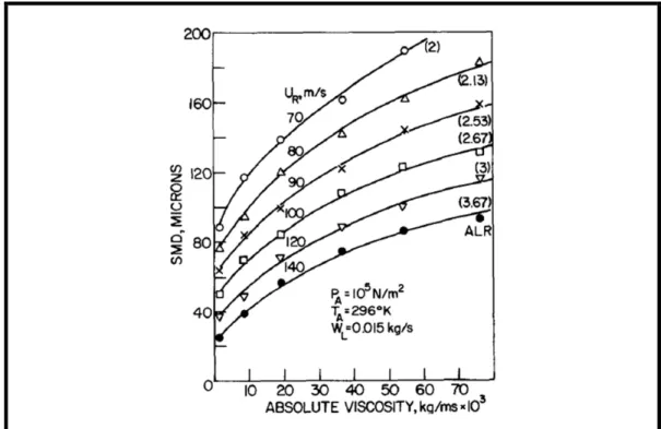
Figure 1.27 SMD variation related to liquid viscosity when using a plain-jet airblast atomizer (Lefebvre, 1980) ...47
Figure 1.28 SMD variation related to surface tension when using for a plain-jet airblast atomizer (Lefebvre, 1980) ...47
Figure 1.29 SMD variation related to liquid density when using a plain-jet airblast atomizer (Lefebvre, 1980) ...48
Figure 1.30 Heat generation zones (Sutter and Ranc, 2007) ...50
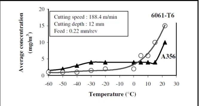
Figure 1.31 Average dust concentration when using A356 and AA6061 – T6 as a function of Workpiece Temperature (Balout, Songmene and Masounav, 2007) ...52
Figure 1.32 Possible dust generation sources (micro level) (Balout, Songmene and Masounav, 2007)...53
Figure 1.33 Dust emission varying on rake angle & cutting speed (dry machining of AA 6061-T6) (Khettabi et al., 2010) ...57
Figure 1.34 Dust emission varying on feed and cutting speed during (dry machining of AA6061) (Khettabi et al., 2010) ...57
Figure 2.1 Coaxial plain-jet airblast atomizer (Steimes et al., 2012) ...63
Figure 2.2 Helos-Vario/KR (www.sympatec.com),consulted on 02/Sep/2012 ...65
Figure 2.3 Microlubrication system (GLS pump) (Manual, Jan 2009) ...66
Figure 2.4 Microlubrication system (SLS1.2-2 pump) (Manual, 2009) ...67
Figure 2.5 Digital Dosing Advanced Pump (DDA) (GRUNDFOS, November 2010) ...68
Figure 2.6 Flow sensor (Manual, Aug 2012) ...70
Figure 2.7 TSI 8532- DustTrak II aerosol monitor (Manual, Jan 2012) ...71
Figure 2.8 Profilometer, Surtronic3+ (SalesBrochure) consulted on 15/Aug./2012 ...72
Figure 2.9 Profilometer, Mitutoyo ...73
Figure 2.10 Injection angle experiment procedure ...75
Figure 2.11 The position of injectors ...76
Figure 2.12 The position of thermocouple ...77
Figure 3.1 Pareto chart of SMD when using nozzles with different diameter and GLS pump ...82
Figure 3.2 Pareto chart of SMD when using nozzles with different diameter and DDA pump ...82
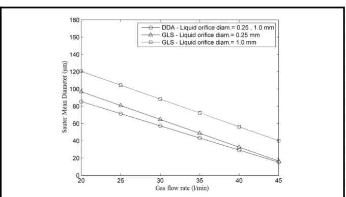
Figure 3.3 SMD related to gas flow rate for GLS and DDA pumps when using nozzles with different liquid orifice diameters ...83
Figure 3.4 Parto chart of injection angle when using nozzles with different diameters and GLS pump...86
Figure 3.5 Pareto chart of injection angle when using nozzles with different diameters and DDA pump ...86
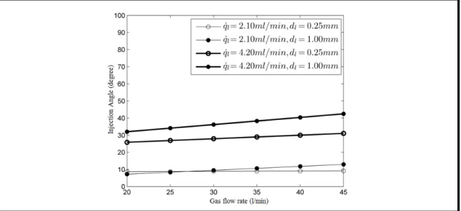
Figure 3.6 Injection angle related to gas flow rate for GLS pump when using nozzles with different liquid orifice diameters ...87
Figure 3.7 Injection angle related to gas flow rate for DDA pump when using nozzles with different liquid orifice diameters ...87
Figure 3.8 SMD related to gas flow rate when using nozzles with different lengths ....90
Figure 3.9 Injection angle related to gas flow rate when using nozzles with different lengths and GLS pump ...92
Figure 3.10 Injection angle related to gas flow rate when using nozzles with different lengths and DDA pump ...93
Figure 3.11 SMD related to gas flow rate when using nozzles with different orifice shapes ...96
Figure 3.12 Injection angle related to gas flow rate when using nozzles with different orifice shapes and GLS pump ...98
Figure 3.17 Main effect plot of injection angle when using nozzles with different lengths and DDA pump ...104 Figure 3.18 Main effect plot of SMD when using nozzles with different liquid
orifice shapes and DDA ...106 Figure 3.19 Main effect plot of injection angle when using nozzles with different
liquid orifice shapes and DDA ...106 Figure 3.20 Particle sizing validation for the injector Lg20.0dl0.25 ...108 Figure 3.21 Particle sizing validation for the injector Lg33.5dl1.00 ...108 Figure 4.1 Surface roughness (μm) variations related to cutting speed (m/min)
where feed rate = 0.10 mm/rev ...112 Figure 4.2 Surface roughness (μm) variations related to cutting speed (m/min)
where feed rate = 0.15 mm/rev ...112 Figure 4.3 Surface roughness (μm) variations related to cutting speed (m/min)
where feed rate = 0.20 mm/rev ...113 Figure 4.4 Main effect plot of surface roughness analysis when using pulsed
pump ...114 Figure 4.5 Pareto chart of surface roughness analysis when using pulsed pump ...115 Figure 4.6 Lg20.0dl0.25 – Surface roughness (μm) variations related to cutting
speed (m/min) ...116 Figure 4.7 Lg33.5dl1.00 - Surface roughness (μm) variations related to cutting
speed (m/min) ...118 Figure 4.8 Feed rate effects on surface roughness when using Lg20.0dl0.25 ...121
Figure 4.9 Feed rate effects on surface roughness when using Lg33.5dl1.00 ...121 Figure 4.10 Lg20.0dl0.25 – tool temperature (oC) variations related to cutting
speed (m/min) ...124 Figure 4.11 Lg20dl0.25 - tool temperature (oC) variations related to cutting
speed (m/min) ...126 Figure 4.12 Gas flow rate effects on tool temperature when using Lg20.0dl0.25 ...129 Figure 4.13 Liquid flow rate effects on tool temperature when using Lg20.0dl0.25 ...130 Figure 4.14 Gas flow rate effects on tool temperature when using Lg33.5dl1.0 ...130 Figure 4.15 Liquid flow rate effects on tool temperature when using Lg33.5dl1.0 ...131 Figure 4.16 Lg20.0dl0.25 – dust concentration (mg/m3) variations related to
cutting speed (m/min) ...133 Figure 4.17 Lg33.5dl1.00 – dust concentration (mg/m3) variations related to
cutting speed (m/min) ...134 Figure 4.18 Gas flow rate effects on dust concentration when using
Lg20.0dl0.25 ...136 Figure 4.19 Gas flow rate effects on dust concentration when using
Lg33.5dl1.00 ...136 Figure 4.20 Liquid flow rate effects on dust concentration when using
Lg20.0dl0.25 ...137 Figure 4.21 Liquid flow rate effects on dust concentration when using
Lg33.5dl1.00 ...137 Figure 4.22 Feed rate effects on dust concentration when using Lg20.0dl0.25 ...138 Figure 4.23 Feed rate effects on dust concentration when using Lg33.5dl1.00 ...138
LIST OF ABREVIATIONS SMD sauter mean diameter
MMD mass mean diameter
MQL minimum quantity lubrication MQC minimum quantity cooling
MQCL minimum quantity cooling lubricant ANOVA analysis of variance
ALR air/liquid mass ratio
Min minimum value
LIST OF SYMBOLS λopt optimum wavelength
f(di) particle size distribution function ni number of the droplets per unit volume
U velocity (m/sec)
UR relative velocity of the gas to liquid (m/sec)
σ surface tension (kg/sec2, or N/m) ρ density (kg/m3)
μ dynamic viscosity (kg/msec, or Nsec/m2) Q volumetric flow rate (1/sec)
DP prefilmer lip diameter (m)
β flow localisation parameter defined by Xie et al. Du dust unit (dimensionless)
EA energy activation Fsh shear force (N) φ shear angle (degree) θ tool rake angle (degree)
δ material parameter
q gas flow rate (l/min) q liquid flow rate (ml/min) dl liquid orifice diameter (mm) L length of injector (mm)
R liquid orifice shape (conical/straight) dge external gas orifice diameter (mm) dgi internal gas orifice diameter (mm) α injection angle (degree)
m mass flow rate (kg/sec) Tg gas temperature (oK) Pg gas pressure (Pa)
INTRODUCTION
Manufacturing has been used for several thousand years by producing the stone, ceramic and metallic articles. From the first industrial revolution until now, there have been great improvements in manufacturing devices from traditional machines all the way to the online manufacturing machines in our days. This revolution allows customers to generate their own products using custom parts provided by online machine shops. Metal cutting is one of the best and useful methods of producing the final shape of parts.
Full understanding of the fundamentals of metal cutting mechanics and quantitative and qualitative analysis of the material removal mechanism are indispensable to achieve the optimum process performance.
The surface roughness, cutting temperature and aerosol emission are the important machining factors. Roughness of final product is considerable in many applications such as tires, floor surface and automobile brake linings. Because of the cutting temperature influence on cutting tool wear; its analysis is a crucial stage of machining studies. The cutting temperature produces the thermal damage and can impose the dimensional inaccuracies to the surfaces of machined workpiece. Nowadays, the manufacturers are interested in minimizing the environmental pollution to produce a cleaner workpiece as well as reducing the lubricant costs. Due to these reasons, dry and semi-dry machining are used frequently however dry machining produces the aerosols. The fine particles (less than 2.5 μm) will go to deepest parts of the lung. The airborne particles introduce a health hazard because they remain suspended in the environment long enough to be inhaled by workers. Comparative study of the amounts of aerosol emission between dry and wet machining has shown that using cutting fluids can decrease the particle formation up to 40 – 50 % (Songmene, Balout and Masounave, 2008b).
The dominant factors on dust generation are tool geometry (rake angle and lead angle), cutting parameters (depth of cut, cutting speed and feed rate) and workpiece materials (Khettabi et al., 2010).
The main objectives of this research are summarized as follow:
1. Investigating governing factors on surface finish quality, heat generation in cutting tool and aerosol emission during turning of 6061-T6 aluminum alloy;
2. Comparing different lubrication mode such as dry, wet and MQC;
3. Presenting a strategy to find the optimum cutting conditions that leads to better machining performance.
Structure of thesis
The present work consists of 4 chapters which are organized as follow: Chapter 1: Literature review
The first chapter presents a comprehensive literature review on various machining methods, atomization, different types of atomizers, laser based techniques for particle sizing, mean drop size prediction and drop size distribution. Furthermore factors governing machining quality index are also introduced, followed by a conclusion of the literature and refining the problematic.
Chapter 2: Instruments and Experimental procedures
Chapter 3: Effects of atomizer geometries on SMD and injection angles (Comparison between the pulsed and non-pulsed pumps)
This chapter consists of the investigation of the nozzle geometry effects on particle sizing and the injection angle which leads to choose the best nozzle geometry in order to use during the experimental study carried out in the following chapters. At the end of this chapter, the results of particle sizing obtained from the experiments performed by laser diffraction method are compared with the empirical equation to validate this experimental study.
Chapter 4: Machining performance when turning aa6061-t6 with pulsed and continuous cooling/lubrication
This chapter consists of three sections as follows:
• Study of the surface roughness using the pulsed and continuous pumps when turning 6061-T6 aluminum alloy.
In this chapter the effects of cutting parameters on surface roughness is studied using the pulsed and continuous pumps and two types of plain-jet airblast nozzles, which are geometrically different. The results discussion is performed to compare the different lubrication methods and to find the conditions which lead to the best surface quality. In this part of work, the effects of different pumps and nozzle geometries on surface roughness are investigated.
• Study of the cutting tool temperature and dust concentration using the continuous pumps when turning 6061-T6 aluminum alloy.
This section discusses about the cutting parameter effects on cutting tool temperature and dust concentration when using the different machining modes such as dry, wet and minimum quantity cooling. The main goal of this part is to find the conditions in which the minimum of heat generation occurred in cutting tool and the dust concentration reaches to its minimum value.
situation but these conditions are different from one to the other. In final section of this chapter of this research the multi response optimization is performed using the desirability function in order to find the optimum setting level of cutting parameters which determines the simultaneous minimization of all the responses.
CHAPTER 1
LITERATURE REVIEW
1.1 Introduction
The process of material removal from a workpiece to convert it into usable part is defined as machining. Metal cutting can be divided into two groups as follow:
1) Conventional machining process such as turning, drilling, grinding, milling, etc.;
2) Non – traditional manufacturing process such as e ultrasonic machining (USM), water jet and abrasive water jet machining (WJM & AWJM), electro discharge machining (EDM).
1.2 Turning
Turning is one of the conventional machining processes used for removing the metal from the outer diameter of a rotating cylindrical workpiece. This process is useful to shape the metal and generate a better surface finish. Turning is performed on a lathe machine in which the tool is stationary and the part is rotated. Using this machine, it is possible to perform four types of turning such as straight turning, taper turning, profiling or external grooving which can produce straight, conical, curved and grooved shaped parts.
In turning process, the most important factors which have to be adjusted before each process depends on material, cutting tool geometry, coating and cutting parameters (see Figure 1.1).
Figure 1.1 Important cutting parameters (Kalpakjian, 2008)
Revolution per minute as unit of cutting speed measurement shows the rotating speed and refers to the spindle and the workpiece. Feed rate is the rate at which the tool advances along its cutting path. The unit of feed rate is millimeter per revolution.
1.3 Machining lubrication modes
The important roles of cutting fluids during machining are decreasing the friction and the temperature by heat dissipation which increases tool life. However the use of cutting fluids is hazardous to operator health and the environment. Furthermore machining cost is anticipated when using cutting fluid.
To reduce the influence of cutting fluids on environment, the lubricants are improved by biodegradable fluids. However there is still bacterial contamination problem that is greatest problems encountered during lubricated machining. To eliminate all of these problems, other machining techniques such as dry and semi-dry machining or minimum quantity cooling lubricant (MQCL) are proposed. In cases with high heat generation, traditional oil can be
replaced with an emulsion which has a higher heat capacity due to its water content. The process in this case is referred to as minimum quantity cooling (MQC), making MQC distinct from MQL (minimum quantity lubrication). MQC is still largely unexplored, although it could provide a solution to processes with high heat generation (Diakodimitris, Hendrick and Iskandar)
These new methods help us to have clean machining and to increase and sometimes completely eliminate the serious problems associated with traditional machining. Most of these problems are caused by metallic particles and dust emissions generated during lubricated cutting.
1.3.1 Wet
Cutting fluids are used to lubricate the tool – chip and the tool – workpiece interface. These are useful for cooling the cutting zone in order to transfer heat. Lubrication is accomplished at low speeds by diffusion through the workpiece and by forming solid boundary layers from extreme pressure additives, but at high speeds, no lubrication is evident (Cassin and Boothroyd, 1965).
For the following three reasons, cutting fluids are not used during high speed machining (Shaw, Pigott and Richardson, 1951):
1) The chips carry the cutting fluid away from cutting zone;
2) The rate of reaction to the cutting fluid is too slow to be effective for high speed operations;
3) The rate of heat generation is greater for high speed operations than low speed operations. Lower resulting values of friction, heat dissipation and better tool life time are the main advantages of wet machining. However the risk of operator health, environment hazard and machining cost increase are the most important disadvantageous of wet machining.
In the metalworking industries, the health of operators and environmental pollution are affected by cutting fluids. In order to reduce these problems, the new method of machining, called Minimum Quantity Lubrication (MQL) is used. With respect to practical point of view, MQL cutting consumes an average of 50 ml of lubricant per processing hour. However, for certain operations (e.g. when using the workpiece with diameter of 40mm or larger), the lubrication consumption rate may exceed 150 ml/h (Unfallversicherung, 2010). Most important advantage of MQL system is that the lubricant supplies directly to the contact area. Due to this small droplet, the thermal shocking of the cutting tool is reduced, which increases the tool life and performance of its operation (Jun et al., 2008). On the other hand, the MQL has also the disadvantages like the inability of complete heat transfer and moving out the chips from the cutting zone which is the cause of part corrosion. In this method, the nozzle must be located not more than 1 or 2 inches from the tool which enables the operator to precisely adjust the nozzle. The performance of MQL machining depends on many factors including lubricant; tools and suitable devices must be compatible. It is also very important that the conditions be properly inspected by the qualified machine operator. Dry machining and MQCL are possible for almost every cutting and non-cutting processes as well as turning, drilling, reaming, thread cutting, thread rolling, milling, hobbling, sawing and broaching (see Table 1.1).
Table 1.1 Applications of MQL & dry machining (DGUV, 2010)
Process
Material
Aluminum Steel Cast
Cast alloy Forged alloy High-alloy Steels, rolling Bearing steel Free-cutting Steel, quenched And tempered steel GG20-GGG70
Drilling MQCL MQCL MQCL Dry Dry
Reaming MQCL MQCL MQCL MQCL MQCL Thread cutting MQCL MQCL MQCL MQCL MQCL Thread rolling MQCL MQCL MQCL MQCL MQCL Deep drilling MQCL MQCL - MQCL MQCL
Milling MQCL Dry Dry Dry
Turning MQCL /
Dry
MQCL /
Dry Dry Dry Dry
Hobbing - - Dry Dry Dry
Sawing MQCL MQCL MQCL MQCL MQCL
Broaching - - MQCL MQCL / Dry MQCL / Dry
1.3.4 Properties of lubricant
Generally, there are several factors which are very important to choose a suitable lubricant. For example, the lubricant smell is substantial because spraying can increase the odor of lubricant. The lubricant must spray easily and also, the additives are very considerable because they should be adjusted to the processing requirements.
than dry and wet machining. Due to the injection of lubricant directly on the cutting zone, this type of machining reduces the cutting temperature which improves the chip-tool interaction. Also reducing the lubricant minimizes the amount of spray and mist which is better for operator health and environment. Finally using the minimum amount of cutting fluid in MQCL helps to reduce the machining cost.
1.4 Atomization
Nowadays, atomization of liquids is an important process in many industrial sectors such as pharmaceutical industries (spray-drying, tablet coating and spray congealing1), automotive painting, combustion, gasification, agriculture and food processing of granular products, surface coating and etc. (Lefebvre, 1989; Liu et al., 2006; Mandato et al., 2012).
1.4.1 Definition
Liquid transformation into a large quantity of small drops is defined as atomization process (Lefebvre, 1980). The result of this phenomenon generates a high relative speed between the liquid and the surrounding gas. Atomization process provides a very high evaporation rates by increasing the surface to mass ratio in the liquid phase (Hede, Bach and Jensen, 2008). In this process, increase in relative speed decreases the frictional forces which generates droplets with smaller median diameters (Hede, Bach and Jensen, 2008).
Conversion of liquid into droplets depends on different parameters such as liquid physiochemical characteristics and nature of nozzle which has a large influence on spray quality (Mandato et al., 2012). The physiochemical properties of liquid are influenced by the
1 Congealing is the transition of a melt from a soft or fluid state to a rigid or solid state by cooling
parameters such as surface tension, density and viscosity. For example, the increase in liquid density causes the increase in droplet size. Unfortunately, it is not a simple correlation between liquid characteristics and droplet size and this problem exists as a result of dependent variations of parameters such as viscosity and surface tension.
1.4.2 Mechanism of atomization
Despite of difficulties existence to understand and model the atomization process, the atomization occurs simply by creating a high relative velocity between the liquid and the surrounding gas. (Hede, Bach and Jensen, 2008; Lefebvre, 1980).
Figure 1.2 Atomization mechanism (Hede, Bach and Jensen, 2008)
Figure 1.2 shows the atomization mechanism. This process is performed during the following steps:
1) The increase in velocity of air or gas. This phase occurs before the contact between the gas and the unstable thin sheet of liquid which forms inside the nozzle. (Lefebvre, 1989). 2) The penetration of high speed gas into the low velocity liquid. This phase disintegrates the
atomization (Lefebvre, 1980). Rayleigh studied the atomization mechanism (see Figure 1.3) by preparing a laminar jet distribution through a circular orifice with initial jet diameter "d". He supposed that small instabilities which cause the breakup are increased when the perturbation increases rapidly at the wavelength equal to 4.51m. After disintegration, the cylinder of length 4.51d becomes a spherical drop, as:
4.51d × d = D (1.1)
finally, the drop diameter, D, is:
Figure 1.3 Rayleigh Atomization Mechanism (Lightfoot, 2007)
In the Rayleigh's analysis the viscosity and the influence of the surrounding air are not considered which is the inconvenience of his investigation (Lefebvre, 1989). Weber developed the Rayleigh's studies and in his analysis considered the effects of air resistance on drops which are being created during jet disintegration. In this case, he studied the influences of lower and higher relative velocities. He could show that in relatively low (zero) velocities, the wavelength has almost the same value which had been obtained by Rayleigh but the increase in relative velocity to 15 m/s reduced the λopt to 2.8d where the drop diameter became 1.6d. This analysis showed that the optimum wavelength for jet breakup is influenced by relative velocity between the liquid jet and surrounding gas (Lefebvre, 1989). According to the Weber's studies, an increase in viscosity leads to an increase in the optimum wavelength of jet breakup. Castleman showed that in presence of air friction, the influence of relative movement between the air and the outer layer of spray is the most important factor for breaking the liquid surfaces and producing the unstable ligaments (Lefebvre, 1980).
explained by Rayleigh theory. Due to this theory the outlet drop diameter is approximately two times greater than initial spray diameter. According to Rayleigh’s investigations, the increase in liquid viscosity and spray velocity, increases and decreases drop size respectively;
2. At higher velocities, the disintegration is due to the entire spray vibration with respect to the spray axis. This mode occurs on a relatively narrow range of speeds;
3. The interaction between liquid and high velocity surrounding air increases the instability of small waves on the spray surface which disintegrates the ligaments into drops with smaller diameters;
4. Atomization is completed by producing the droplets with diameters significantly smaller than initial spray diameter which is occurred at very high relative velocities and after a short distance from the discharge orifice.
1.5 Atomizers and pulverization
1.5.1 Introduction
Due to the importance of the atomization process in industrial areas, it is crucial to classify the different types of atomizers. This classification is according to the parameters such as geometry, usage environment and related forces or velocities and is not founded on atomization mechanisms (Lightfoot, 2007). In this part of the literature review, the different types of atomizers will be presented.
1.5.2 Different lubrication systems
According to the manufacturing process, there are internal and external lubrication systems. The main task of an MQL system is to supply the appropriate lubricants on the cutting edge (contact point of the tool).
• Internal lubrication systems
The best way of lubrication is the direct injection of lubricant on the cutting zone. In this method, the lubricant is continually available at the critical points during the entire cutting process. The using of MQCL with internal feeds enables us to achieve this idea. In the internal lubrication system, the lubricant arrives to the cutting zone through the spindle, tool revolver and the inner cooling channels of the tool (Unfallversicherung, 2010). This system is useful for very deep hole drilling at very high cutting speeds (table 1.1). In this way, we will have the maximum amount of lubricant during drilling process. This system needs special tools and appropriate machines but this equipment increase the process cost. There are two devices (one-channel and two-channel) which are used for internal lubrication (see Figure 1.4). These devices are different in term of required channels in the rotating chuck, spindles and the place of aerosol production. The internal lubrication systems do not need to adjust the feed nozzle. Therefore, there is not huge amount of loss due to dispersion (Unfallversicherung, 2010).
Figure 1.4 One-channel and Two-channel systems (Unfallversicherung, 2010)
One and two channel devices
In the one-channel systems (see Figure 1.5) , there is a tank where the aerosol is generated with the aid of compressed air, and it arrives to tool through the rotary chuck, spindle and tool holder (Unfallversicherung, 2010). In the two-channel devices (see Figure 1.6); the aerosol production is performed in the mixture embedded in a pipe nozzle. Air and oil are fed separately using two channels through the tool spindle to the tool holder. The lubricant is transported via a high speed valve, where the metering process is done. Therefore the optimal quantity of the lubricant will be sent to the two channel rotary chuck. The transported lubricant and the supplied air are mixed in the mixing chamber of the pipe nozzle.
Figure 1.5 One-channel system for internal feed (Unfallversicherung, 2010)
of lubrication system.
In these systems, using the special tools is not necessary and the process cost is less than internal systems. But unlike internal systems, in external lubrication, there is a lot of loss due to the dispersion and the operator must adjust the nozzles manually.
Devices with metering pump2 and with pressure tank
In the metering pump devices (see Figure 1.7); a pneumatic micro-pump is responsible for the lubricant transportation. The controlling and regulation of the lubricant dosage is done by means of the stroke and frequency of the pump plunger.
In the pressure tank devices (see Figure 1.8); the lubricant will be exited with the pressure of the pressurized tank. By using the throttle valve and the supply pressure settings, metering will be done. Adjustments of tank pressure, atomisation of air and oil quantity separately, guarantee the good performance of this system (Unfallversicherung, 2010). Table 1.2 shows the comparison of devices with metering pump &pressure tank.
2 A metering pump transfers an accurate volume of liquid during a specified time to produce a precise flow rate. (www.wikipedia.org/wiki/Metering_pump) consulted on 10/June/2012
Table 1.2 The comparison between metering pump and pressure tank (Unfallversicherung, 2010)
Metering pump Pressure tank
Advantages
Exact dosage volume settings Uniform lubrication stream Exact modular design Lack of moving parts Possibility to install any number of
pump elements Lack of wear
Disadvantages Pulsating lubricant stream
Precise adjustment of oil dosage volume is limited on some degrees Wear in moving parts number of outputs is limited
Figure 1.8 Device with pressure tank (Unfallversicherung, 2010)
1.5.3 Nozzle performance properties
The performance of a nozzle will be presented by different nozzle characteristics which are described briefly as follows:
1. The injected liquid flow related on the nozzle feed pressure; 2. The injection angle of the spray produced by nozzle;
3. The ratio between the energy of the spray and the energy used by the nozzle; 4. The uniformity of the injected flow;
1.5.4 Different types of atomizers
In different industrial applications, the atomization processes of large number of nozzles are based on the capillary3 and aerodynamic4 break up. Besides these atomizers, there are others such as electro-spraying, plasma spraying and etc., which use the diverse types of energy to apply in atomization processes (Batarseh, 2009). The different types of atomizers used in most industrial applications will be described in following passages.
• Pressure atomizers
As explained previously, one of the important factors related to the atomization is to achieve the high relative velocity between the liquid and the surrounding air or gas. To approach this relative velocity, the pressure atomizers are used to convert the pressure into the required kinetic energy (Lefebvre, 1999). Various types of such atomizer, such as plain-orifice atomizers, simplex atomizers and the dual-orifice atomizers are described as follows.
Plain orifice atomizers
The easiest technique to atomize a liquid is to inject it through a small circular hole. This system is occurred in the plain orifice atomizers. The liquid disintegration into small droplets is performed by injection at high velocity. The necessary velocity will be obtained by increasing the liquid pressure to the ambient gas pressure (almost 150 kPa). The increase in liquid injection pressure leads to increase in liquid jet turbulence and aerodynamic forces applied by the surrounding medium (Lefebvre, 1999). An illustration of this type of atomizer is shown in Figure 1.9.
3 Capillary action is a consequence of the liquid surface tension when liquid moves through thin tubes and capillary break up is a result of liquid ejection from a nozzle at high velocity and under the high injection pressure. (www.wikipedia.com ) (consulted on 12/Aug.2012)
4 Aerodynamic breakup is due to the shear stresses at the liquid-gas interface. (www.wikipedia.com) (consulted
Figure 1.9 Plain orifice atomizer (Lefebvre, 1999)
Providing the narrow sprays with cone angles is one of the disadvantages of plain orifice atomizers.
Simplex atomizers
The simplex atomizers function is based on liquid swirling motion accompanying the centrifugal forces. These types of the atomizers are used to achieve the wider cone angles compared with the plain orifice atomizers. As it is shown in Figure 1.10, liquid being injected into a swirl chamber passes through the tangential ports which are used to create a higher angular velocity and the air-cored vortex. At final orifice, the liquid which is under axial and radial forces will be injected as a hollow conical sheet (Lefebvre, 1999).
Figure 1.10 Simplex atomizer1(Lefebvre, 1999)
Dual orifice atomizers
The dual orifice atomizers as shown in Figure 1.11 have two parts as primary or pilot nozzle and secondary or main nozzle. This type of atomizer could be compared with two simplex nozzles which are fitted concentrically. Depending on liquid quantity supplied in this nozzle, two different functions will be performed in this type of atomizer (Lefebvre, 1999).
• Liquid with low quantity: In this situation, the liquid flows through the small port of the primary nozzle where the liquid pressure will be increased. Due to the high pressure, the quality of liquid atomization will be improved;
• Liquid with high quantity: The increase in liquid amount and therefore the increase of the liquid pressure allow the port to open and enter the secondary nozzle. The atomization quality will be more and improves by increasing the amount of liquid and its pressure.
Figure 1.11 Dual orifice atomizer (Lefebvre, 1999)
Spill return atomizers
The main difference between this atomizer and simplex one is the existence of a passage in the rear wall of the swirl chamber which allows the extra liquid to return back into the supplier tank (Lefebvre, 1999), (see Figure 1.12).
The advantages of this atomizer are as follow (Lefebvre, 1999):
• Providing a liquid injection at high pressure even at the lowest liquid flow rate; • Excellent atomization quality;
• Absence of moving parts and independency from plugging by contaminations in the fuel.
The disadvantages of this atomizer are as follow (Lefebvre, 1999): • High fuel-pump power necessity;
• Large variation in spray cone angle with the change in the fuel flow rate; • Complexity of the flow rate metering;
Figure 1.12 Spill return atomizers (Lefebvre, 1999)
• Rotary atomizers
The best example of the rotary atomizer is slinger system which is used in combination with a radial-annular combustion chamber. In this type of the atomizer, the low pressure liquid feeds into a hollow main shaft and gets injected radially through the shaft holes. The Slinger system fabricated by Turbomeca, the French company, is shown in Figure 1.13. The main advantages and disadvantages of this system are desribed as follow (Lefebvre, 1999):
Advantages:
• Simple system with low cost; • Low pressure fuel pump necessity; • Satisfactory atomization quality;
• Less impact of the viscosity and ability to use different types of liquid consequently. Disadvantages:
• Slow response to the change in liquid flow due to the long flow path;
Figure 1.13 Turbomeca slinger system (Lefebvre, 1999) • Air assist atomizers
There are two different types of the air assist atomizers such as internal-mixing and external-mixing configuration which are shown in Figures 1.14 – 15. These two types are very useful for atomizing the high viscosity liquids (Lefebvre, 1999).
Figure 1.14 Internal-mixing air assist atomizers (Lefebvre, 1999)
• Airblast atomizers
The main function of the airblast atomizers is based on using the kinetic energy to transform the initial liquid-phase into the ligaments and droplets. This principal is the same as the one that is used in the air assist atomizers while the most important differences between these two nozzles are the air quantity employed and their atomizing velocity (Batarseh, 2009; Lefebvre, 1999).
The airblast nozzles produce the smaller sprays and they need the low pressure fuel pumps. This nozzle is very useful especially for high pressure combustion systems (Lefebvre, 1999) whereas the poor atomization associated with the low air velocity is the weak point of the airblast atomizers (Batarseh, 2009). Three types of the airblast atomizers which are described as follow are the plain-jet, the prefilming and the piloted airblast atomizers shown in Figure 1.16.
Figure1.16(a) Plain-jet atomizer
Figure 1.16(c) Piloted atomizer
Figure 1.16 Different types of the airblast atomizers (Lefebvre, 1999) Plain-jet airblast atomizers
The plain-jet airblast nozzle is the simplest form of airblast atomizers. Its function is based on the injection of a round jet of liquid along the axis of a generally co-flowing round jet of air (Lefebvre, 1999).
This type of the atomizer (see Figure 1.17) is very useful to study the influences of the air and the liquid characteristics on the mean drop size such as Nukiyama and Tanasawa (1939) investigations which will be described in part 1.6 of this chapter.
Figure 1.17 Plain-jet airblast atomizer (Lefebvre, 1999) Prefilming airblast atomizers
The airblast atomizers are usually used to increase the supplied air in order to increase the atomized liquid phase (Batarseh, 2009). Nowadays, in different industrial applications, the pre-filming airblast atomizers are the most useful nozzles in which the liquid is firstly spread out into a thin continuous sheet and then will be subjected to the atomizing action of the high-velocity air (Lefebvre, 1999). This type of atomizer is shown in Figure 1.18.
Figure 1.18 Pre-filming airblast atomizer (Lefebvre, 1999)
Due to use of pre-filmer nozzle structure, the liquid phase is pushed by a pressure swirl atomizer. As a result the gas phase will be interacted with the liquid film inside and outside the atomizer (Batarseh, 2009). The pre-filmer function is shown in Figure 1.19.
Figure 1.19 Prefilmer function in airblast atomizer (Batarseh, 2009)
Piloted airblast atomizers
The main objective of piloted airblast atomizer (see Figure 1.20) is to increase the atomization performance when it is carried out using the low air velocity. This type of airblast nozzles is made by a prefilming airblast atomizer with a simplex pressure swirl nozzle which is installed on its centerline. Because of this structure, the piloted airblast atomizer is known as a hybrid injector (Lefebvre, 1999).
Figure 1.20 Piloted airblast atomizer (Lefebvre, 1999)
1.5.5 Common features of different twin-fluid atomizers
The various nozzles previously described are known as twin-fluid atomizers. The principal function of all twin-fluid atomizers is using the air as a first force in order to increase the atomization.
In these atomizers the injection of the low velocity air makes the bubbles which create a two-phase bubbly flow at the discharge orifice. The rapid expansion of the air bubbles emerged from the nozzle will break the liquid sheet up into small droplets (Lefebvre, 1999).
1.6 Prediction of mean drop size and drop size distribution
1.6.1 Introduction
Particle size measurement is become very important in research and development as well as in industrial applications (Lee Black, McQuay and Bonin, 1996). The increasing in pollutant emissions and the low price of residual fuel oils encourage researchers, scientists and engineers to investigate the droplet size distribution in the fuel nozzle sprays (Semião, Andrade and Carvalho, 1996). In engineering systems, the droplet size distribution is a
fundamental parameter to analyse the transport of the mass, momentum, and heat (Liu et al., 2006). According to the atomization description, this process is complicated and because of its random nature, most of the practical atomizers do not produce sprays of homogeneous droplet size at any given operating conditions. Therefore, it is crucial to understand the investigation methods of the droplet size (Liu et al., 2006).
1.6.2 Definition
All laser-based methods of the particle sizing are able to measure the spherical particles. Consequently, all the measured particles have the equivalent diameters if they are considered spherical (Lee Black, McQuay and Bonin, 1996).
All the particle size distribution functions are generally in relation to different aspects of flow such as volume or concentration. The basic mathematical function of the particle size distribution is a function of f(di) which is the value of the particle size distribution function at
the discrete values of the particle size, represented by di in equation 1.3 (Lee Black, McQuay
and Bonin, 1996).
(d ) = ∑ ( )
∑ ( ) (1.3)
There are different definitions of mean particle diameters such as arithmetic mean, the surface mean, the volume mean and the Sauter mean, etc. Each one is known with a symbol like d10, d20, d30, d32, d43, etc. which are used generally in equation 1.3. These symbols are used in the phenomena under the investigations, for example, d32 is used in the combustion related fields and d43 is used in the field of the chemical kinetics (Lee Black, McQuay and Bonin, 1996). The different definitions of the mean drop size are explained in table 1.3.
d20 2,0 Surface mean
area of the particles in the size distribution d30 3,0 Volume mean
diameter
Diameter of a sphere with the average volume of the particles in the size distribution
d21 2,1 Surface diameter Diameter of a sphere having the surface area of the average particle size in the distribution d31 3,1 Volume diameter Diameter of a sphere having the volume of the
average particle size in the distribution
d32 3,2 Sauter mean diameter
Diameter of a sphere with the equivalent surface to volume ratio as all the particles in the size distribution
d43 4,3 Weight mean Diameter of a sphere having the average weight of all the particles in the size distribution
Between all these definitions, the Sauter Mean Diameter (SMD) is used more than the others due to its relevance to the rate of the evaporation and combustion (Lefebvre, 1980). Several parameters such as atomizing fluid properties, nozzle design and operating conditions affect the Sauter Mean Diameter (Semião, Andrade and Carvalho, 1996). The general function of SMD is:
SMD = ∑
∑ (1.4)
where di and ni are the droplet diameter (for airblast atomization process) and the number of
1.6.3 The empirical correlations related on the mean drop diameter
The SMD prediction for different types of atomizers such as airblast and Pressure-jet atomizers is based on semi-empirical correlations obtained from experimental data and the physical and dimensional analysis of the atomizing process. All of these equations are proposed related on different factors such as nozzle design features and physical flow properties of the air and the liquid employed (Lefebvre, 1980; Semião, Andrade and Carvalho, 1996). In this section, several predictions of SMD related to airblast atomizers are presented.
• Plain-jet airblast atomizers Investigations Nukiyama and Tanasawa
The coaxial two-fluid airblast atomizers are applicable in different industrial applications such as gas turbines and liquid propellant rocket engines (Liu et al., 2006). Seventy years ago, the first investigation on plain-jet airblast atomizers was performed by Nukiyama and Tanasawa, who obtained a drop size equation as a function of the injection parameters. The airblast atomizer that is used in this study is shown in Figure 1.21. The measurements of gasoline, water, oils and solutions of alcohol and glycerin atomization were conducted by the sample collections of the spray on the glass slides coated by oil.
Figure 1.21 Nukiyama and Tanasawa plain-jet airblast atomizer (Lefebvre, 1980; Liu et al., 2006)
The analysis carried out by Nukiyama and Tanasawa led to the equation 1.5 for drop size in which the air density is kept constant (at the normal atmospheric value) during all experiments. This assumption is one of the major limitations of this equation because of the requirement of many combustion systems to operate over wide ranges of air pressure and temperature. Furthermore, the tests derived by Nukiyama and Tanasawa with different sizes and shapes of nozzles and orifices showed that these factors have almost no effect on mean drop size (Lefebvre, 1980; Liu et al., 2006).
Gretzinger and Marshall
Gretzinger and Marshall (Gretzinger and Marshall, 2004) were interested in the study of drop size distribution using two types of airblast atomizers such as converging and impingement nozzles. In converging nozzles which were used by Nukiyama and Tanasawa, the liquid will be contacted with the atomizing airstream at the throat of the air nozzle while in impingement nozzles, a central circular air tube is surrounded by an annular liquid channel (Lefebvre, 1980). The equations obtained by Gretzinger and Marshall are shown as follows (Equations 1.6 and 1.7 for converge and impingement nozzles respectively).
MMD = 2.6 × 10 3( mL mA)( μA ρAUAL) 0.4 (1.6) MMD = 1.22 × 10 ( ) . ( ) . (1.7)
where MMD is Mass Mean Diameter (m) which is the drop diameter related to the 50% point on the cumulative mass distribution curve (Lefebvre, 1980).
Despite the lack of the direct study of the air viscosity which affects the mean drop size, an important characteristic of these equations is that they include the air viscosity parameter. It is concluded that increasing the nozzle size decreases the mean drop size which leads to produce the finer sprays (Lefebvre, 1980).
Kim and Marshall
The two different forms of airblast atomizers are used during the research of the drop size distribution performed by Kim and Marshall (Kim and Marshall Jr, 1971). These forms are convergent single airblast nozzle and double concentric airblast atomizer. The first one works based on converging and expanding the atomizing air through a curl around a liquid nozzle. The other one is made of a secondary air nozzle which is placed axially in the liquid nozzle. The atomizer used in Kim and Marshall research is shown in Figure 1.22 (Lefebvre, 1980).
Figure 1.22 Kim & Marshall atomizer (Lefebvre, 1980)
The relevant measurements of drop size carried out by Kim and Marshall are according to the information shown in table 1.4 (Lefebvre, 1980).
Table 1.4 The parameters used in Kim and Marshall drop size measurements (Lefebvre, 1980)
Liquid viscosity 0.001- 0.050 kg/msec
Relative air velocity 75-393 m/sec
Air to liquid mass flow ratio 0.06-40
Liquid density 800- 960 kg/m3
Air density 0.93-2.4 kg/m3
The equations 1.8 and 1.9 are obtained from Kim and Marshal experiments for convergent single airblast nozzle and double concentric airblast atomizer respectively.
MMD = 5.36 × 10 ( ).. .. . + 3.44 × 10 ( ) . ( ) . (1.8)
MMD = 2.62( .) . . . + 1.06 × 10 ( ) . ( ) . (1.9) According to these equations, it is concluded that the significant operating variables in airblast atomization are the air/liquid mass ratio and the dynamic force. The increases in each one or both of them reduces the mean drop size (Lefebvre, 1980).
Lorenzetto and Lefebvre
Lorenzetto and Lefebvre (1977) were a research group who investigated accurately the efficiency of plain-jet atomizers. The system which was used in their studies is shown in Figure 1.23. In this system, different parameters such as air/liquid ratio, air velocity, atomizer dimensions and the physical characteristics of liquid could be changed independently in a broad range (Lefebvre, 1980).
Figure 1.23 Lorenzetto and Lefebvre atomizer (Lefebvre, 1980)
This atomizer was also included the equipment which could produce a round jet of liquid surrounded by a co-axial and co-flowing stream of high velocity air. The drop size equation
Jasuja
The other research of the mean drop size carried out by Jasuja (Jasuja, 1979) using a plain-jet airblast atomizer with kerosene and the other different fuels (see Figure 1.24).
Figure 1.24 Plain-jet atomizer used by Jasuja (Lefebvre, 1980)
The SMD equation (Equation 1.11) obtained from this experimental work has the same characteristics of the Lorenzetto and Lefebvre equation with the exception of lower dependence of SMD on air/liquid mass ratio.
SMD = . ( ) . (1 + ) . + 0.127( ) . (1 + ) (1.11)
Weiss and Worsham
According to Weiss and Worsham investigations (Weiss and Worsham, 1958) the most important parameter to control the mean drop size is the relative velocity between the air and the liquid. The research carried out by Weiss and Worsham contains both cross stream and co-stream injection of the liquid jets into the air at high velocity and it is based on the parameters shown in table 1.5 (Lefebvre, 1980).
Table 1.5 The parameters used in Weiss and Worsham drop size measurements (Lefebvre, 1980)
Air velocity 60 - 300 m/msec
Orifice diameters 1.2 - 4.8 mm
Liquid viscosities 0.0032 - 0.0113 kg/msec
Air densities 0.74 - 4.2 kg/m3
The mean drop size equation (Equation 1.12) obtained from their experimental studies is based on dependence of the drop size distribution to the variety of excitable wavelengths on the surface of a liquid sheet (Lefebvre, 1980).
size.
Figure 1.25 Rizkalla and Lefebvre atomizer (Lefebvre, 1980)
According to experimental results obtained by Rizkalla and Lefebvre, it was concluded that the main factors which affect the mean drop size are surface tension, air velocity and air density for the low viscosity liquids. Rizkalla and Lefebvre found that the liquid viscosity effect is independent from that of the air velocity. The equation obtained from the Rizkalla and Lefebvre researches (Equation 1.13), shows clearly this independence using two separate terms as air velocity and air density for the first one and the liquid viscosity as the second term (Lefebvre, 1980).
SMD = 3.33 × 10 ( ) . 1 + + 13.0 × 10 ( ) . D . (1 + ) (1.13)
The comparison between prefilming and the plain-jet airblast nozzles carried out by Lefebvre and Rizkalla (see Figure 1.26), showed that the performance of the prefilming atomizers is better than that of the plain-jet atomizers particularly under the conditions such as low air/liquid ratio and/or low air velocity (Lefebvre, 1980).
Figure 1.26 Atomizing efficiency of the plain-jet and the prefilming atomizers (Lefebvre, 1980)
1.6.4 The effects of variables on mean drop size
According to researches conducted on drop size distributions, the most important variables which affect mean drop size are viscosity, surface tension and density of liquid as well as the air velocity. Several effects of these properties and their results are explained in table 1.6 (Lefebvre, 1980). The influences of these parameters on plain-jet airblast atomizers are shown in Figures 1.27 and 1.29.