Science Arts & Métiers (SAM)
is an open access repository that collects the work of Arts et Métiers Institute of Technology researchers and makes it freely available over the web where possible.
This is an author-deposited version published in: https://sam.ensam.eu Handle ID: .http://hdl.handle.net/10985/11199
To cite this version :
Phuoc Hoa TRUONG, Damien FLIELLER, Ngac Ky NGUYEN, Jean MERCKLE, Guy STURTZER - Torque ripple minimization in non-sinusoidal synchronous reluctance motors based on artificial neural networks - Torque ripple minimization in non-sinusoidal synchronous reluctance motors based on artificial neural networks - Vol. 140, p.37-45 - 2016
Any correspondence concerning this service should be sent to the repository Administrator : archiveouverte@ensam.eu
1
Torque Ripple Minimization in Non-Sinusoidal
Synchronous Reluctance Motors Based on
Artificial Neural Networks
Phuoc Hoa Truong1 , Damien Flieller2, Ngac Ky Nguyen3, Jean Mercklé1, Guy Sturtzer4
1 MIPS Laboratory - University of Haute Alsace, 4 Rue des Frères Lumière, 68093 Mulhouse - France. [phuoc-hoa.truong, jean.merckle]@uha.fr
2 GREEN Laboratory - INSA de Strasbourg, 24 Boulevard de la Victoire, 67084 Strasbourg - France. damien.flieller@insa-strasbourg.fr
3 Univ. Lille, Centrale Lille, Arts et Metiers ParisTech, HEI, EA 2697 - L2EP – Laboratoire d’Electrotechnique et d’Electronique de Puissance, F-59000 Lille, France.
ngacky.nguyen@ensam.eu
4 LGECO Laboratory - INSA de Strasbourg, 24 Boulevard de la Victoire, 67084 Strasbourg - France. guy.sturtzer@insa-strasbourg.fr
Abstract — This paper proposes a new method based on Artificial Neural Networks for
reducing the torque ripple in a non-sinusoidal Synchronous Reluctance Motor. The Lagrange optimization method is used to solve the problem of calculating optimal currents in the d-q frame. A neural control scheme is then proposed as an adaptive solution to derive the optimal stator currents giving a constant electromagnetic torque and minimizing the ohmic losses. Thanks to the online learning capacity of neural networks, the optimal currents can be obtained online in real time. With this neural control, each machine’s parameters estimation errors and current controller errors can be compensated. Simulation and experimental results are presented which confirm the validity of the proposed method.
Keywords: Non-sinusoidal Synchronous Reluctance Motor, Torque Ripple, Optimal Currents, Lagrange Optimization, Adaline, Artificial Neural Networks.
2 1. Introduction
ynchronous reluctance motor (SynRM) has received much attention for many applications in recent years due to its structural simplicity, low manufacturing cost and rugged construction [1]-[3]. However, a high level of torque ripple which produces mechanical vibrations and acoustic noise is one of the major drawbacks of this motor.
Torque smoothness is an essential requirement in many applications. Therefore, many authors have proposed different methods to minimize the torque ripple with this kind of machine. In [4], the authors pointed out that there are two approaches that minimize the torque ripple of synchronous motors. The first one consists of techniques to adjust the machine’s stator and rotor design in order to cancel the undesirable torque ripple. The authors in [5]-[7] proposed the methods for reducing the torque ripple by adjusting the flux barrier in rotor structure. The effect of rotor skewing to minimize the torque ripple has been studied in detail [8]-[9]. The authors in [8] and [9] show that the torque ripple is minimized when the rotor is skewed with an angle which is equal to a stator slot pitch.
The second approach is based on the active control schemes which modify the stator currents and propose the best currents for cancelling the undesired torque ripple. The authors in [10] worked in the d-q frame in order to calculate the optimal currents. The copper losses in this method are not minimized because the direct current is forced to be equal to the quadrature one Id= Iq. Also working in the d-q reference frames, the works presented in [11]-[13] give the expressions of optimal currents to minimize the torque ripple. The authors of [11] and [12] propose an extended Park transformation to obtain optimal currents in the non-sinusoidal machine, while the authors in [13] obtain optimal currents to achieve a maximum torque-to-current condition which takes into account the effect of magnetic saturation. Based on input–output linearization, the authors in [14] and [15] propose a method to obtain optimal
3
currents that give the constant torque and minimize the losses. Nonlinear controllers are proposed in [14] to regulate the torque by selecting the product of d-axes and q-axes torque currents as one of the output variables. The cross-coupling effects and iron losses are taken into account in [14]. Based on sliding mode control (SMC) [16], the value of the reference current is adjusted in order to keep the speed of the motor constant. Therefore, the torque ripple of the motor is minimized. The injection of current harmonic is proposed in [17], the disadvantage of this method is high torque ripple because the authors optimize the currents only for harmonics of ranks 5 and 7. Recently, based on direct torque control (DTC), the works in [18]-[21] have proposed controlling the stator flux and generating the torque. In [19], the amplitude and angle of the commanding voltage vectors were derived from the errors of torque and flux. Therefore, the torque and flux-ripples are minimized. Based on torque predictive control [20], the optimized voltage is utilized to reduce torque ripple. In that method, the voltage angle vector is determined from the output of torque and flux hysteresis controllers. Another method based on the injection of high-frequency current presented in [21], the MTPA point can be detected because the variation in the torque based on the variation in the current angle is zero at the MTPA points. In [22], the optimal currents are obtained based on emotional controller and space vector modulation (SVM) under an automatic search of the MTPA strategy. In [23], the estimated difference of d-q inductance was used to achieve MTPA control and accurate torque control. While all of these authors work only with sinusoidal machines, in this paper we work instead with non-sinusoidal SynRMs.
Unlike the approaches mentioned above, in this paper we use an adaptive technique based on Artificial Neural Networks (ANNs) [25]-[26] to obtain the optimal stator currents. These optimal currents minimize the copper losses and give exactly the electromagnetic torque
4
desired in non-sinusoidal SynRMs. The ANNs presented in this paper is the Adaline (ADAptive LInear NEuron), which uses an online learning process based on the Widrow– Hoff algorithm. Therefore, the optimal currents are obtained online in real time. Moreover, comparing our copper losses with those from previous methods confirms the validity of the proposed method.
The remainder of this paper is organized as follows: torque calculation of the SynRM is presented in Section 2. Section 3 presents the Lagrange optimization method to obtain the optimal currents. The investigation of Adaline Neural Networks for torque and speed controllers is proposed in Section 4. Simulation and experimental results are shown in Section 5 and 6 respectively. Finally, some conclusions are given in Section 7.
2. Torque computation of synchronous reluctance motors
The electromagnetic torque of the SynRM is expressed as:
( )
1 2 T e p T L i i (1) where
T a b c i i i i is the stator currents vector.
p : The number of pole pairs, and : the mechanical angle. The matrix of inductances
L(p)
is expressed as follows:
( ) ( ) a ab ac ab b bc ac bc c L M M p M L M M M L p p p p p p p p p L (2)whereLa(p), (Lb p), (L pc : the self- inductances. ) Mab(p),Mbc(p),Mac(p): the mutual inductances.
5
In the case of sinusoidal excitation, the currents vector is expressed as:
2. cos 2 2.I cos 3 2 2.I cos 3 rms rms rms I p p p i (3)with : the load angle. Therefore, in order to maximize the mean value of electromagnetic torque, the load angle is chosen as:
= 45° [10].An accurate of self and mutual inductances is necessary in the analysis of the SynRM. Because of rotor saliency and stator windings distribution, the self and mutual inductances of a SynRM are non-sinusoidal. The electromagnetic torque produced by this machine presents the torque ripple when it is fed by sinusoidal currents [11], [25].
The measurement of the self and mutual inductances is realized on our laboratory machine test bench. The measurements are done at the stand-still [10]-[11]. The results of the measurements are compared with the Finite Element Method (FEM) when using JMAG software (see Fig.1). The comparison of the FEM and measurement results of the self and mutual inductances is shown in the Fig. 2 and Fig. 3 respectively. One can be seen that the errors between the FEM and measurement results are not significant.
The expressions of the self and mutual inductances with the significant harmonics are:
0.204 0.113cos 2 0.0295 cos 4 0.007 cos 6
2 2 2
0.093 0.129 cos 2 0.01cos 4 0.006 cos 6
3 3 3 a ab L p p p p M p p p p (4)
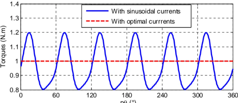
The electromagnetic torque obtained with the sinusoidal currents for the SynRM whose parameters are presented in equation (4) is shown in Fig. 4. It can be noticed that the torque
6
ripple is important (around 39% of the required value). Therefore, the optimal currents are thus required for reducing the torque ripple in this SynRM. In the next section, we will present the calculation of optimal currents to achieve MTPA strategy by means of the Lagrange optimization in order to reduce torque ripple.
3. Optimal currents based on Lagrange optimization
The Park’s transformation is defined as:
2 2
cos( ) cos( ) cos( )
2 3 3
2 2
3 sin( ) sin( ) sin( )
3 3 p p p p p p P (5)
Using Park’s transformation and assuming the zero sequence of current to be zero lead to:
. a d T b q c i i i i i i P (6)where ,i id q are the d and q current components.
Replacing (6) in (1), the electromagnetic torque is rewritten as:
1 . 2 T d T d e q q i p i T i i L P P (7)Let us define the matrix [A] as follows:
21
p
T a p(( )) c p(( )) c p b p L A P P (8)By replacing (8) in (7), the electromagnetic torque Te becomes:
2 2
( ) ( ) 2 ( )
e d q d q
7
In order to obtain the desired electromagnetic torque and minimize the copper losses (MTPA strategy), we use the Lagrange optimization.
The cost function is defined as the copper losses: 2 2
.( )
j s d q
P R i i (10)
wherePj: the copper losses, Rs: the stator resistance. This task leads to establish a Lagrange function:
2 2 2 2
( d q) (Te ( d q 2 d q))
L i i
a i b i c i i (11) with
: Lagrange’s multiplier.The derivations of L according to ,i id q respectively give:
2 iq ( 2 b iq 2 c id) 0 (12) 2 id ( 2 a id 2 c iq) 0 (13) From (12), we obtain (14):
_ _ 1 d opt q q opt ai
i
i
c
(14)where id opt_ , iq opt_ : the d and q optimal current components.
Replacing iq opt_ in (9) and choosing id opt_ > 0:
_ 2 2 2 2 2 2 ( ) (2 2 ) e d d opt T i i a b a c c a b b c (15)
From (12) and (13), we obtain as expressed in (16):
2 2 1 2 2 2 2 2 ( ) ( ) 4 with 0 2 ( ) ( ) ( ) 4 with 0 2 ( ) e e a b a b c T a b c a b a b c T a b c (16)
8
Finally, three phase optimal currents will be obtained by:
_ _ _ _ _ . a opt d opt T b opt q opt c opt i i i i i P (17)Fig. 5 shows the phase currents and d-q currents in two different strategies of machine supply: sinusoidal currents and optimal currents given by expressions (14)–(17). It is obvious that in order to obtain a desired electromagnetic torque and minimize the copper losses in the non-sinusoidal SynRM, the machine stator currents are not sinusoidal to compensate the torque ripple.
Fig. 4 compares the electromagnetic torque when the machine is fed by the optimal phase currents with the one obtained by the sinusoidal currents. As can be seen, the torque ripple was totally cancelled when using the optimal phase currents. This numerical result confirms the validity of the Lagrange’s method.
In next section, we will present a new method based on Adaline Neural Networks to obtain the optimal currents. Thanks to learning capacity of neural networks, the optimal currents will be obtained online and each machine’s parameters estimation errors can be compensated. That is the advantages of ANNs compared with the Lagrange optimization.
4. Investigation of Adaline Neural Networks for torque and speed controllers
4.1. Main ideas for the torque and speed control: From (14), we can rewrite iq opt_ as:
_ _ _ , (1 ) , ( ) e e d optq opt opt d opt
a i T p i K p i T p c (18)
9 where: (1 ) ( ) opt a K p c (19)
The principal idea for the torque and speed controllers comes from the axis q optimal currents in (18). We can observe that this current results from a scalar product of two components: the first one is the optimal functionKopt(p), and second one is the axis d
optimal current id opt_ ( ,T pe . )
Fig. 5b) and Fig. 6 show the current id opt_ ( ,T pe and the optimal function ) Kopt(p)for the presented non-sinusoidal SynRM. We can observe that id opt_ and Kopt are the periodic functions, it is thus possible to learn and estimate them by using Adaline Neural Networks. Therefore, we propose to learn online id opt_ ( ,T pe ) by one Adaline controller and estimate off-line Kopt(p) by another Adaline with an input vector composed of cos(kp) and
sin(kp) terms with k varying from 0 to 20 [26]. After convergence, the function Kopt(p )
is estimated with:
( ) 1 0.062sin(6 ) 0.002sin(12 ) 0.001cos(12 )
opt
K p p p p (20)
It can be noticed that Kopt(p contains very few harmonics and it is independent of the ) electromagnetic torque Te .
We can write the optimal current id opt_ (p) by the sum of the Fourier’s terms:
0 1 _ ( ) ( aisin( ) bicos( )) N i d d d d opt i p i i ip i ip
(21)where N: the highest considered harmonic.
10 0 * 1 1 ... aN bN T d da db d d i i i i i W (22)
The optimal current
i
d opt_ will be learned and synthesized by the Adaline controller. Thedetails are presented in the Section 4.2.
4.2. Torque and speed controllers based on Adaline Neural Networks:
We can remark that the torque (or speed) errors between the desired torque
T
ref and the calculated torque Te in Fig. 7 is necessary for deriving the optimal currenti
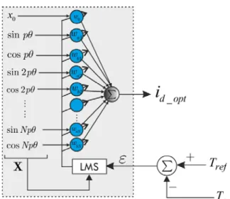
d opt_ . We definethe input vector of Adaline as:
0 sin( ) cos( ) ... sin( ) cos( )
T x p p Np Np
X (23)
Similarly, the weights of the Adaline are defined as:
0 1 1 ...
T a b aN bN w w w w w W (24)These weights are solved using an iterative linear LMS (Least Mean Square) algorithm [24] in order to minimize the torque (or speed) errors. They are adjusted according to:
(k 1) ( )k . ( ). ( )k k
W W X (25)
Where X is the input vector, is a learning rate, is the torque (or speed) errors.
The Adaline controllers have to ensure that the electromagnetic torque (or speed) of the motor converge toward the desired one. Therefore, the weights of the Adaline are also enforced to converge toward values:
*
W W (26)
11 5. Simulation of the proposed method by Adaline Neural Networks
To confirm the validity of the proposed method presented in the previous sections, a Matlab/Simulink program is used to simulate for the non-sinusoidal SynRM and the Adaline Neural Networks. The self and mutual inductances are expressed in (4). The reference speed is fixed at 1000 [rpm] in the simulation. The value of the training parameter used for simulation is fixed to 0.002(a justification is given in the subsection 6.1). The parameters of the machine for simulation and experimental tests are shown in Table I. The torque and speed controllers based on Adaline Neural Networks are presented in Fig. 8. It can be noticed that the current controllers shown in this figure are PI controllers.
The results of neural torque control are shown in Fig. 9 with the desired torque
2
ref
T [N.m]. The optimal currents obtained online by Adaline controllers are close to their references as shown in Fig. 9a) to reduce the torque ripple. It can be noticed that the torque ripple obtained with proposed method in Fig. 9b) is not significant (only 2% of the desired torque) and the convergence of this strategy takes approximately one electrical cycle (about 25 ms). The weights of the Adaline are also learned online and their convergence is shown in Fig. 9c).
A simulation work with a varying torque is presented in order to evaluate the dynamic response of the proposed technique. Fig. 10 shows the obtained results when we change the desired torque to Tref [N.m] at t = 0.1s. 5 It can be seen that a good response of Adaline’s
method is achieved by observing the optimal currents in Fig. 10a) and the torques obtained in Fig. 10b) converging to the reference values in a short time (about 20 ms). This good result of torque control is ensured by a convergence of the Adaline network’s weights as shown in Fig. 10c).
12
Fig. 11 shows the comparison of the copper losses between the proposed methods and previously discussed method. It can be noticed that these results are presented in [25] with the SynRM type massive rotor. It is obvious that the copper losses are not minimized when
d q
i i as proposed by the authors in [10] (with 5% higher than the proposed method). The simulation results demonstrate a good performance of Adaline Neural Networks for minimizing the torque ripple.
6. Experimental results
The experimental platform is presented in Fig. 12. A three phase SynRM is connected to a three-phase voltage source inverter. The machine parameters are given in Table I. The rotor’s position and the stator currents are measured in real time by using an incremental encoder and currents sensors. The measures are sent to a dSPACE DS1104 board hosted by a personal computer. The ANN controller has been implemented using the ACE 1104 board (DSPACE) with Matlab/Simulink.
6.1. Neural Torque Control
The neural torque control is presented in the Fig. 8 when the switch s = 1. It can be noticed that the estimated electromagnetic torque will be calculated from the measured currents and the inductances of the SynRM as shown in Fig. 2 and Fig. 3.
The experimental results in steady state with the desired torque Tref 0.8 N.m
are reported in Fig. 13. Fig. 13a) compares the reference currents obtained by the proposed method with an Adaline controller and the measured currents. It is shown that the resulting currents provided by the neural controller are close to their references. The non-sinusoidal currents obtained with the Adaline controller compensate the torque ripple. Fig. 13c) shows13
the comparison of the electromagnetic torque obtained with the optimal currents with the one derived by the sinusoidal currents. It can be noticed that the torque ripple by optimal currents is about 8% of the desired torque and 38% when the machine is fed by the sinusoidal currents. We can remark that in this case, the currents in d-q frame from Fig. 13b) have the higher harmonics. Therefore, the Adaline controller is a good candidate to choose in order to compensate the higher harmonics to minimize the torque ripple.
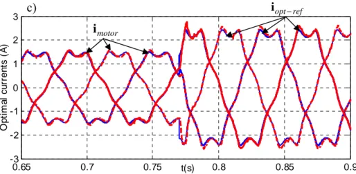
In order to show the convergence of our method, we present the results with dynamic torque as shown in Fig. 14. In this case, the desired torque Te 2.5 N.m
(about 36% of thenominal torque is applied at time t = 0.77s. Fig.14a) and 14b) show the electromagnetic torque and the optimal phase currents obtained with the Adaline controller respectively. It can be noticed that the torque and currents obtained with the Adaline controller converge in a short time (about 50 ms), approximately with a half electrical cycle of the machine which is acceptable in many practical applications.
The experimental performances under load reduction are also presented in Fig. 15. As can be seen, the convergence of the proposed method within a short time. Fig. 16 shows the experimental tests under nominal load Tref 7 N.m
. We can remark that the torque ripple byoptimal currents is about 13% of the desired torque and 44% when the machine is fed by the sinusoidal currents. These experimental results show the good performance of the proposed method based on an Adaline Neural Network.
In classical torque control, except the DTC control, the references of current are obtained by an analytical formulation from the torque, for example the MTPA-based vectorial control algorithm. Thus, an overshoot of torque depends strictly to the current controller performance.
14
If a good design of the current control is achieved, the overshoot can be avoided. It is the case where IP (Integrate-Proportional) controllers are used and a double pole is imposed.
We can remark that the torque response of the proposed method shows an overshoot (see Figs. 9b), 10b) and 14a), both in simulation and experimental tests. Indeed, the references of current are determined through a learning process of Adaline whose the training dynamic has a significant impact on the torque response in the close loop. The parameter that modifies the dynamic of convergence is the tuning factor η. Theoretically, this parameter could vary between 0 and 1 but a study more details has been given in [24] for choosing a good value without destabilize the system. In our work, the right values of η are given in the Fig. 17 where there are some torque responses corresponding to different values of η (with the same current controllers). We can see that the torque response based on Adaline seems like a classical PI controller where there is always a compromise between the dynamic and the overshoot for a step excitation.
Simulation and experimental results given in the paper have been obtained with η=0.002. It was a choice for a compromise between the dynamic response and the torque response time. Now, it is possible to cancel completely the overshoot by taking η smaller but the torque response time is more important as shown in the Fig. 17.
A higher value of η could leads to an instability of the drive. This is verified in Fig. 18 where we see the drive losses the control of torque with η=0.01.
6.2. Neural Speed Control
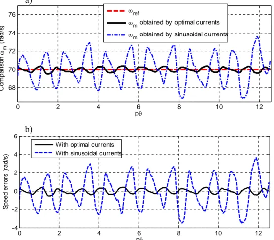
The neural speed control is shown in the Fig. 8 when the switch s = 0. A constant reference speed has been fixed at ω = 70 (rad/s). ref
15
Fig.19a) shows the comparison of the speed obtained with the proposed method and the one when the machine is fed by the sinusoidal currents. We can observe that the speed pulsation of the proposed method with an Adaline is much reduced in Fig. 19b). It is obvious that there is a torque ripple when the machine is supplied by the sinusoidal currents which lead to the speed pulsation. By using the proposed method, the torque and speed ripple that is presented in the control of conventional SynRM has been solved.
7. Conclusions
In this paper, we have proposed a new method based on Adaline Neural Networks for minimizing the torque and speed ripple in non-sinusoidal SynRMs. Thanks to this method, we can derive the optimal stator currents that precisely give the electromagnetic torque desired while minimizing the copper losses. With their learning capacity, short convergence time and good stability, the neural networks can obtain the optimal currents online in real time. The Adaline controllers take the place of the conventional torque or speed controller to ensure that the motor’s torque or speed converge toward the desired ones. Our simulation and experimental results clearly show that the torque and speed ripples have been much reduced and the convergence of the proposed method is achieved within a short time. Furthermore, comparing our copper losses with those from previous methods confirms the validity of our new approach.
16 References
[1] S. Taghavi and P. Pillay, "A Sizing Methodology of the Synchronous Reluctance Motor for Traction Applications," IEEE J. Emerg. Sel. Topics Power Electron., vol. 2, no. 2, pp. 329-340, Jun. 2014.
[2] M. Ferrari, N. Bianchi, A. Doria and E. Fornasiero, "Design of Synchronous Reluctance Motor for Hybrid Electric Vehicles," IEEE Trans. Ind. Appl., vol. 51, no. 4, pp. 187-195, Jul./Aug. 2015.
[3] R. R. Moghaddam and F. Gyllensten, "Novel High-Performance SynRM Design Method: An Easy Approach for A Complicated Rotor Topology," IEEE Trans. Ind. Electron., vol. 61, no. 9, pp. 5058-5065, Sep. 2014.
[4] T. M. Jahns and W. L. Soong, "Pulsating torque minimization techniques for permanent magnet AC motor drives-a review," IEEE Trans. Ind. Electron., vol. 43, no. 2, pp. 321-330, Apr. 1996.
[5] A. Vagati, M. Pastorelli, G. Francheschini and S.C. Petrache, "Design of low-torque-ripple synchronous reluctance motors," IEEE Trans. Ind. Appl., vol. 34, no. 4, pp. 758-765, Jul./Aug. 1998.
[6] N. Bianchi, M. Degano and E. Fornasiero, "Sensitivity Analysis of Torque Ripple Reduction of Synchronous Reluctance and Interior PM Motors," IEEE Trans. Ind. Appl., vol. 51, no. 1, pp. 187-195, Jan./Feb. 2015.
[7] N. Bianchi, S. Bolognani, D. Bon, and M. Dai Pre, "Rotor Flux-Barrier Design for Torque Ripple Reduction in Synchronous Reluctance and PM-Assisted Synchronous Reluctance Motors," IEEE Trans. Ind. Appl., vol. 45, no. 3, pp. 921-928, May/ Jun. 2009.
[8] X. B. Bomela and M. J. Kamper, "Effect of stator chording and rotor skewing on performance of reluctance synchronous machine," IEEE Trans. Ind. Appl., vol. 38, no. 1, pp. 91-100, Jan./ Feb. 2002.
[9] R. Islam, I. Husain, A. Fardoun and K. M. Laughlin, "Permanent-Magnet Synchronous Motor Magnet Designs With Skewing for Torque Ripple and Cogging Torque Reduction," IEEE Trans. Ind. Appl., vol. 45, no. 1, pp. 152-160, Jan./Feb. 2009.
[10] T. Hamiti, T. Lubin, L. Baghli, andA. Rezzoug, "Modelling of a synchronous reluctance machine accounting for space harmonics in view of torque ripple minimization," Mathematics and Computers in Simulation, vol. 81, pp. 354-366, Aug. 2010.
[11] G. Sturtzer, D. Flieller and J.-P. Louis, "Mathematical and experimental method to obtain the inverse modeling of nonsinusoidal and saturated synchronous reluctance motors," IEEE Trans. Energy Convers., vol. 18, no. 4, pp. 494-500, Dec. 2003.
[12] Y. Ait-gougam, R. Ibtiouen, O. Touhami, J.P. Louis and M. Gabsi, "Inverse modelling and pulsating torque minimization of salient pole non-sinusoidal synchronous machines," Electric Power Systems Research, vol. 78, pp. 88– 96, 2008.
[13] C. Mademlis, "Compensation of magnetic saturation in maximum torque to current vector controlled synchronous reluctance motor drives," IEEE Trans. Energy Convers., vol. 18, no. 3, pp. 379-385, Sep. 2003.
[14] L. Hyeoun-Dong, K. Seog-Joo and S. Seung-Ki, "Efficiency-optimized direct torque control of synchronous reluctance motor using feedback linearization," IEEE Trans. Ind. Electron., vol. 46, no. 1, pp. 192-198, Feb. 1999.
[15] H. Abootorabi Zarchi, J.Soltani and G.A. Markadeh, "Adaptive Input-Output Feedback-Linearization-Based Torque Control of Synchronous Reluctance Motor Without Mechanical Sensor," IEEE Trans. Ind. Electron., vol. 57, no. 1, pp. 375-384, Jan. 2010.
17
[16] N. Inanc and V. Ozbulur, "Torque ripple minimization of a switched reluctance motor by using continuous sliding mode control technique," Electric Power Systems Research, vol. 66, pp. 241-251, 2003.
[17] L. Geun-Ho, K.Sung-Il, H.Jung-Pyo and J.H. Bahn, "Torque Ripple Reduction of Interior Permanent Magnet Synchronous Motor Using Harmonic Injected Current," IEEE Trans. Magn., vol. 44, no. 6, pp. 1582-1585, Jun. 2008. [18] X. Zhang, G. H. B.Foo, D. M.Vilathgamuwa and D. L. Maskell, "An Improved Robust Field-Weakeaning Algorithm for
Direct-Torque-Controlled Synchronous-Reluctance-Motor Drives," IEEE Trans. Ind. Electron, vol. 62, no. 5, pp. 3255-3264, May 2015.
[19] Z. Yongchang, Z. Jianguo, X. Wei and G. Youguang, "A Simple Method to Reduce Torque Ripple in Direct Torque-Controlled Permanent-Magnet Synchronous Motor by Using Vectors With Variable Amplitude and Angle," IEEE Trans. Ind. Electron, vol. 58, no. 7, pp. 2848-2859, July 2011.
[20] Z. Hao, X. Xiao and L. Yongdong, "Torque Ripple Reduction of the Torque Predictive Control Scheme for Permanent-Magnet Synchronous Motors," IEEE Trans. Ind. Electron, vol. 59, no. 2, pp. 871-877, Feb. 2012.
[21] S. Bolognani, L. Peretti and M. Zigliotto, "Online MTPA Control Strategy for DTC Synchronous-Reluctance-Motor Drives," IEEE Trans. Power Electron., vol. 26, no. 1, pp. 20-28, Jan. 2011.
[22] E. Daryabeigi, H. Z. Abootorabi, G. R. A. Markadeh, J. Soltani and F. Blaabjerg, "Online MTPA Control Approach for Synchronous Reluctance Motor Drives Based on Emotional Controller," IEEE Trans. Power Electron., vol. 30, no. 4, pp. 2157-2166, Apr. 2015.
[23] H. Wenqing, Z. Youtong, Z. Xingchun and S. Guan, "Accurate Torque Control of Interior Permanent Magnet Synchronous Machine," IEEE Trans. Energy Convers., vol. 29, no. 1, pp. 29-37, Mar. 2014.
[24] B. Widrow and E. Walach, "Adaptive Inverse Control," Prentice-Hall, 1996.
[25] T. Phuoc Hoa, D. Flieller, N. K. Nguyen, J. Mercklé and G. Sturtzer "An investigation of Adaline for torque ripple minimization in Non-Sinusoidal Synchronous Reluctance Motors," in Proc. IEEE 39th Annu. Conf. Ind. Electron. Soc. IECON 2013, Vienna, Austria , Nov. 2013, pp. 2602-2607.
[26] D. Flieller, N. K. Nguyen, P. Wira, G. Sturtzer, D. O. Abdeslam and J. Mercklé "A Self-Learning Solution for Torque Ripple Reduction for Non-sinusoidal Permanent-Magnet Motor Drives Based on Artificial Neural Networks," IEEE Trans. Ind. Electron, vol. 61, no. 2, pp. 655-666, Feb. 2014.
18 List of tables
Table I. Parameters of the SynRM under simulation and experimental tests List of figures
1. Fig. 1. Meshed FEM model of the studied SynRM by JMAG 2. Fig. 2. Self inductance La
3. Fig. 3. Mutual inductance Mab
4. Fig. 4. Torques obtained in two cases: sinusoidal currents and optimal ones (simulation result) 5. Fig. 5. Comparison in two cases : with and without optimal currents (simulation results) 6. Fig. 6. The optimal function Kopt of the studied SynRM
7. Fig. 7. The optimal current id opt_ learned by the Adaline
8. Fig. 8. Torque and speed controllers of the SynRM based on Adaline Neural Networks 9. Fig. 9. Simulation results with Tref 2 (N.m)
10. Fig. 10. Simulation results with dynamic torque control 11. Fig.11. Comparison of the copper losses with previous method 12. Fig. 12. Experimental platform setup.
13. Fig. 13. Experimental performances with Tref 0.8 (N.m) when m 35 (rad/s) 14. Fig. 14. Experimental performances with load increasing when m 35 rad/s
15. Fig. 15. Experimental performances under load reduction when m 35 rad/s
16. Fig. 16. Experimental performances under nominal load Tref 7 N.m
when
45 rad/s
m
17. Fig. 17. Torque responses corresponding to different training coefficients η 18. Fig. 18. Torque responses corresponding to higher values of η
19. Fig. 19. Experimental speed obtained by the optimal currents compared with the one obtained by the sinusoidal currents
19 Fig. 1. Meshed FEM model of the studied SynRM by JMAG
0 60 120 180 240 300 360 0.05 0.1 0.15 0.2 0.25 0.3 p (°) La ( H ) FEM Experimental 0 5 10 15 0 0.05 0.1 0.15 0.2 0.25 Harmonic Ma g n it u d e ( H ) FEM Experimental
Fig. 2. a) Self-inductance La; b) Harmonics of self-inductance La
0 60 120 180 240 300 360 -0.2 -0.1 0 0.1 p (°) Mab ( H ) FEM Experimental 0 5 10 15 0 0.05 0.1 0.15 0.2 Harmonic M agn itu d e (H ) Experimental FEM
Fig. 3. a) Mutual inductance Mab; b) Harmonics of mutual inductance Mab
a) b)
20 0 60 120 180 240 300 360 0.8 0.9 1 1.1 1.2 1.3 1.4 p (°) T o rque s ( N .m )
With sinusoidal currents With optimal currrents
Fig. 4. Torques obtained in two cases: sinusoidal currents and optimal ones (simulation results).
0 60 120 180 240 300 360 -2 -1 0 1 2 p (°) P h ase c u rr en t i a ( A ) Optimal current Sinusoidal current 0 60 120 180 240 300 360 1.4 1.6 1.8 2 2.2 p(°) d -q c u rr e n ts ( A )
Optimal current iqopt Optimal current idopt id=iq in case sinusoidal
a) Current of the phase a b) Currents in d-q frame Fig. 5. Comparison in two cases: with and without optimal currents (simulation results).
0 60 120 180 240 300 360 0.92 0.96 1 1.04 1.08 1.1 p (°) K opt
Optimal function Kopt
0 5 10 15 20 0 0.2 0.4 0.6 0.8 1 Harmonics M a gni tude K op t
a) The optimal function Kopt b) Harmonics of Kopt
21 Fig. 7. The optimal current id opt_ learned by the Adaline
22 0 0.02 0.04 0.06 0.08 0.1 -3 -2 -1 0 1 2 3 4 P h a s e c u rre n t ia (A ) Adaline's current Theorical currrent 0 0.02 0.04 0.06 0.08 0.1 0 0.5 1 1.5 2 2.5 T o rque ( N .m ) Applied Obtained 0 0.02 0.04 0.06 0.08 0.1 -1 -0.5 0 0.5 1 1.5 2 2.5 t (s) Wei g h ts
Fig. 9. Simulation results with Tref 2 N.m
a) Optimal current (phase a) obtained by the Adaline; b) Torque obtained; c) Weights of Adaline.
a)
b)
23 0 0.05 0.1 0.15 0.2 -5 -3 -1 1 3 5 P h a s e c u rr e n t ia (A
) Adaline's currentTheorical current
0 0.05 0.1 0.15 0.2 0 1 2 3 4 5 6 7 T o rq u e (N .m ) Applied Obtained 0 0.05 0.1 0.15 0.2 -1 0 1 2 3 4 5 t (s) We ig h ts
Fig. 10. Simulation results with dynamic torque control
a) Optimal current (phase a) obtained by the Adaline ; b) Torque obtained; c) Weights of Adaline
1 2 0.95 1 1.05 1.1 Methods C o pp e r l o ss es (p u )
Our optimal currents
Solution proposed by Hamiti [10] when id=iq
Fig.11. Comparison the copper losses with previous method
a) b) c) 1 , 1 05
24 Fig. 12. Experimental platform setup.
0 2 4 6 8 10 12 -2 -1 0 1 2 2.4 p O p ti ma l c u rre n ts (A ) 0 2 4 6 8 10 12 1 1.1 1.2 1.3 1.4 1.5 1.6 1.7 p C u rre n ts i d , iq (A ) id measured iq measured a) b) opt ref i motor i
25 0 2 4 6 8 10 12 0.7 0.8 0.9 1 1.1 p To rq u e s ( N .m ) Torque-ref
Torque with optimal currents Torque with sinusoidal currents
Fig. 13. Experimental performances with desired torque Tref 0.8 N.m
when m 35 rad/s
a) iopt -ref obtained and currents consumed by the SynRM imotor; b) Currents ,i i measured; d q
c) Electromagnetic torque estimated.
0 0.3 0.6 0.9 1.2 1.5 1.75 0.5 1 1.5 2 2.5 3 t(s) To rque ( N .m ) 0 0.3 0.6 0.9 1.2 1.5 1.75 -3 -2 -1 0 1 2 3 t(s) Mo to r c u rr e n ts ( A ) a) b) c)
26 0.65 0.7 0.75 0.8 0.85 0.9 -3 -2 -1 0 1 2 3 t(s) Op tim a l c u rr e n ts ( A )
Fig. 14. Experimental performances with load increasing when m 35 rad/s
a) Electromagnetic torque obtained; b) Currents consumed by motor imotor;c) Zoom t = [0.65s - 0.9s] of iopt -ref and imotor
0 0.3 0.6 0.9 1.2 1.5 1.7 0.5 1 1.5 2 2.5 3 t(s) To rq u e ( N .m ) 0 0.3 0.6 0.9 1.2 1.5 1.7 -3 -2 -1 0 1 2 3 t(s) M o to r c u rr e n ts (A )
Fig. 15. Experimental performances under load reduction when m 35 rad/s
a) Electromagnetic torque obtained; b) Currents consumed by motor imotorc) b) a) motor i opt ref i
27 0 2 4 6 8 10 12 -5 -2.5 0 2.5 5 p Op ti ma l c u rr e n ts (A ) 0 2 4 6 8 10 12 5 6 7 8 9 10 p To rque s ( N .m ) Torque-ref
Torque with sinusoidal currents Torque with optimal currents
Fig. 16. Experimental performances under nominal load Tref 7 N.m
when m 45 rad/s
a) iopt -ref obtained and currents consumed by the SynRM imotor ; b) Electromagnetic torque
estimated. a)
b)
motor
28 0 0.05 0.1 0.15 0.2 0.25 0 1 2 3 4 5 6 7 8 Time [s] T o rq ue s [N .m ] =0.0003 =0.001 =0.0008 =0.0005 =0.002 =0.003
Fig. 17. Torque responses corresponding to different training coefficients η
0 0.05 0.1 0.15 0.2 0.25 -15 -10 -5 0 5 10 Time [s] T o rques [N .m] T ref T e with =0.008 T e with =0.01
29 0 2 4 6 8 10 12 68 70 72 74 76 p C o m p ar is on m (r a d /s ) ref
m obtained by optimal currents m obtained by sinusoidal currents
0 2 4 6 8 10 12 -4 -2 0 2 4 6 p S p ee d er ro rs ( rad/ s )
With optimal currents With sinusoidal currents
Fig. 19. Experimental speed obtained by the optimal currents compared with the one obtained by the sinusoidal currents: a) Speed ; b) Speed errors
Table I. Parameters of the SynRM under simulation and experimental tests
Parameter Value
Rated power PN= 1.1 [kW]
Rated current Irms 3 [A]
Stator resistance R = 6.2 [Ω] s
Rated speed N= 1500 [rpm] Rated torque: TN= 7 [N.m]
Pole pairs number p2
Inertia of rotor J= 0.002 [kg.m2]
a)