2212-7976/16 $100.00+.00 © 2016 Bentham Science Publishers 730050, P.R. China; 2Wenzhou Pump & Valve Engin. Research Institute, Lanzhou University of Tech-nology. Wenzhou 325105, P.R. China; 3University of Liege, Energy Systems Research Unit, Liege, 4000, Belgium; 4College of Mechanical Engineering, Chongqing University of Technology, Chongqing, 400054, P.R. China
Received: April 7, 2015; Accepted: October 12, 2015; Revised: November 9, 2015
Abstract: Traditionally, scroll compressors are mainly made of metallic parts and oil is used to
lubri-cate the friction surfaces and reduce discharge temperature and leakage. But for the food processing,
medical systems, textile manufacturing, fuel cell system, and other super-clean fields, the oil-less operation is critical. The oil is strictly forbidden in the working chambers of the scroll compressor in order to get the oil-free compressed air. So it is very important to develop the oil-free scroll compressor (OFSC). In this paper, the working principle and structure characteristics of the OFSC are investigated. Some of research works and the recent patents in this area are described and analyzed in detail, especially the water injection and air cooling OFSC. The future development on an OFSC is also pre-sented. The analysis results demonstrated that there is dramatic growth potential in OFSC field.
Keywords: Cooling, oil-free, performance, scroll compressor, sealing, structure, water.
1. INTRODUCTION
Scroll compressor is a new kind of positive machine. Scroll compressor has many favorable features, including simple structure, lower vibrations, and high volumetric effi-ciency relative to other types of compressors. With the de-velopment of the scroll compressor, it has been become more and more popular in many fields.
In order to achieve superior operating efficiency and reli-ability, oil is injected into the compression chambers of scroll compressors. The motivation for oil injection in scroll compressors is that oil should be able to seal the leakage gaps between fixed and orbiting scrolls. In addition, the oil can help to control the discharge temperature of the com-pressor by absorbing some of the heat of the fluid as it goes through the compression. However, for the food processing, medical systems, textile manufacturing, cryogenics, fuel cell stacks and other ultra-clean applications, oil stains cannot be tolerated and is strictly prohibited in this kind of field. One possible means of achieving oil-free compressed air is through the use of oil filter, and the other one is to adopt an OFSC. Using the OFSC is more valid compared with oil filter because it eliminates the need for lubricants.
OFSC means no oil in working chambers. It can provide oil-free and contaminant-free compressed air, eliminate envi-ronmental emissions and protect natural resources. This pa-per will describe some of the recent advances in the area of
*Address correspondence to this author at the School of Mechanical and Electronical Engineering, Lanzhou University of Technology. Lanzhou 730050, P.R. China; Tel: 086-931-2973860; Fax: 086-931-2757293; E-mail: [email protected]
OFSC. In part 2, a basic background of scroll compressor will be presented. In part 3, the recent technologies of OFSC will be given and discussed. In part 4, a typical OFSC will be presented. In part 5, the paper will be concluded with some perspectives of future research [1].
2. SCROLL COMPRESSOR
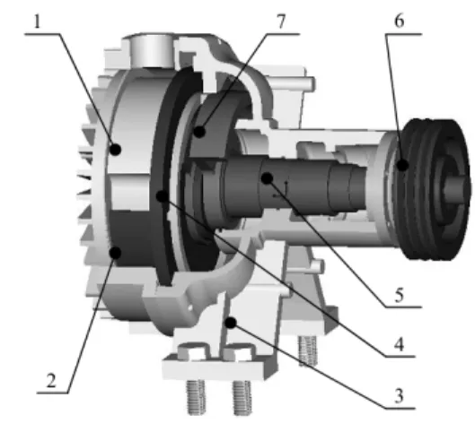
Figure 1 is the typical horizontal scroll compressor where
the main parts are presented. In the scroll compressor one scroll is fixed, the other orbiting scroll is connected to the driven crankshaft. The phase difference of fixed and orbiting scrolls is 180°. The anti-rotational mechanism is located be-tween the shell and the orbiting scroll. The goal of the anti-rotational mechanism is simply to avoid the rotation of the orbiting scroll and maintain the relative angle of the fixed and orbiting scrolls, still allowing its orbiting movement. The working chambers between the fixed and orbiting scrolls moved along the profiles. The working principle of OFSC is shown in Fig. (2). Fluid gets trapped in the suction chamber (a) through a port. With the crankshaft rotates, the suction chamber moved through the profiles which has now become the compression chambers (b), (c) and (d). In the compres-sion process, the comprescompres-sion chambers is decreasing gradu-ally and compressing the fluid. When the compression chamber is connected to the exhaust hole in the center dis-charge region (e) of the fixed scroll, the fluid is disdis-charged by the outlet. In scroll compressors, the fixed and orbiting scrolls define two paths for the working fluid. Usually, the two paths are symmetric, leading to the same pressure changes inside each one [1].
1. Fixed scroll 2. Orbiting scroll 3. Shell 4. Anti-rotational mechanism 5. Crankshaft 6. Belt with small counterbalance 7. Big counterbalance
Fig. (1). The typical horizontal scroll compressor.
Fig. (2). Working principle of scroll compressor.
In 1886, the working principle of a scroll compressor first appeared in the Italian patent literature (Beseler, 1887) [2]. In 1905, the French engineer formally proposed the principle and structure of a scroll compressor, and applied for a US patent (Leon Creux, 1905). In the 1970s, the US
company-ADL firstly solved the scroll ends wear compensa-tion sealing technology which guided the technological growth and put scroll machines into practice. In 1981, scroll compressors began to be mass-produced in Japan by Sanden Corp. It was the first company to begin the production for automotive air conditioning scroll compressors. In 1983, Hitachi began to use 2-5HP scroll compressors for refrigera-tion and air condirefrigera-tioning. In 1987, Copeland Corp. has turned scroll compressor theory into practical reality with mass production. At present, with the widespread use in the industry areas, scroll compressor has become the main prod-uct in small and medium sized compressors [3].
Almost 4700 US and European patents have been dis-closed in scroll compressor area during the year 1975-2015. Figure 3 is US patents and European patents growing trend of scroll compressor (1975-2015). The main development period began in 1982 and the patents of scroll compressor grew to the peak in 2002. There is a small fall after 2002 and then gradually increased till it reached the maximum in 2014. Figure 4 presents the major scroll compressor compa-nies that have patented innovations about scroll compressors between 1975 and 2015. From the scroll compressor patents and market share analysis it shows that Copeland Corp. is the biggest competitor in scroll compressor area. The com-panies from US and Japan account for nearly two-thirds of total patents. Today, OFSC due to its unique features and energy saving, has aroused many researchers’ great interest. Along with the widely used of OFSC in requirement of clear environment of industry, OFSC is becoming the develop-ment trend in this field [4].
3. OFSC
In academic publications, some researchers have done a lot of works in OFSC. Lai [5] designed and tested an OFSC for an electric vehicle. This paper focused on the topics of concept design and analysis, component manufacturing, pro-totyping assembly and performance testing. In structure de-sign, the influences of scroll pitch, wrap height, wrap width and crank radius for compressor performance were consid-ered. Figure 5 is the prototype of OFSC. An optimized com-bination of geometric scroll parameters, accurate counter-weight calculations, suitable bearings and precise machining were used to develop this OFSC. Figure 6 is the comparisons of the performance test results with different design changes of axial and radial clearance. In Fig. (6), the [Change1]
duced the size of axial and radial clearance about 50% and 30% respectively from the original design. The [Change 2] further modified the axial clearance about 10% smaller than [Change 1]. The test results showed that the performance of newly developed prototype compressor satisfies the original requirements. Large clearance will lead to large leakage and the lower limit of the clearance is related to what is feasible in practice (tolerances, machining imprecision and deforma-tion). So the appropriate size of axial and radial clearance is very important for OFSC performance.
Fig. (5). The prototype of OFSC.
Fig. (6). The performance of OFSC.
Zhao [6, 7] investigated the detail performances of the water injection OFSC for a fuel cell. Figure 7 shows the struc-ture of scroll compressor without using oil and grease. In order to lower the discharge temperature, water is used to control the discharge temperature of the compressor and lubricate the friction surfaces. In order to reduce the the overall machine weight and avoid rusting, aluminum alloy and titanium alloy are used as the materials of the fixed and orbiting scrolls. Tef-lon is used in the bearing to reduce friction and wear. A mathematical model of OFSC for the automotive fuel cell was investigated. The heat transfer and leakage in scroll compres-sor were considered. The numerical simulation results of compressor power are in good agreement with the test results in less than 7.28% of the mean deviation as shown in Fig. (8). Fig. (4). Major scroll compressor companies from US patents and EP patents analysis (1975-2015).
Fig. (7). The structure of water injection scroll compressor.
Fig. (8). Comparison of compressor powers.
Wang [8] constructed an OFSC as shown in Fig. (9) and investigated the performance of compressor used in the re-frigeration system of the aerospace and aircraft. The self-lubricating, long-life tip seal ensures the axial gap of com-pressor. The ball bearing is adopted as anti-rotational mechanism to maintain the relative angle and movement of scrolls. The compressor can operate efficiently without oil and expensive filtration. The gap of the orbiting and fixed scrolls is kept around 30μm. The mathematical modeling of the OFSC was developed. The numerical simulation results show good agreement with the test results with less than mean deviation of 10%.
Yanagisawa et al. showed that the volumetric and total
efficiencies of the compressor are 87% and 56% respectively under the conditions of discharge pressure 700kPa and
rota-tion speed 2720rpm. Figure 10 is the structure of OFSC. On the other hand, Yanagisawa showed the performance of the same compressor, but in air expansion mode, to be respec-tively 76% and 60% for volumetric and total efficiencies, which occur under the conditions of having a pressure sup-ply of 650kPa and a rotation speed of 2500rpm [9, 10]. Aoun et al. and Lemort et al. [11, 12] investigated
ex-perimentally the performance of a scroll expander that comes from an OFSC, which was tested by Yanagisawa. Aoun im-proved the volumetric efficiency by replacing the original tip seal of the expander by a polytetrafluorethylene (PTFE) seal. Experimental results obtained after the modification show 20% increase in the volumetric efficiency without affecting the isentropic efficiency. The increase in volumetric effi-ciency is mainly due to the lower axial clearance between the seals and the wraps of the expander, while the isentropic efficiency was maintained due to the low leakage flow. Lemort used water steam and HCFC-123 as working fluid to investigate the performances of a scroll expander. Two dif-ferent mathematical models of the expander are developed. Through performance test, the models are finally verified. The analysis results provide guidance for the structure design of scroll expander.
Fig. (9). The OFSC used in the refrigeration system.
Fig. (11). Plastic OFSC.
Shaffer [13] designed a new compressor and built from both plastic and metallic materials. The proposed compressor design mitigates the overturning moment by placing the crank shaft bearing in-line with the resulting radial force as shown in Fig. (11). It can eliminate the overturning moment. It is important to include a self-lubricating material between surfaces in contact. Plastic compressors are significantly more susceptible to thermal deformation than metallic com-pressors. Because of this, the plastic compressor with an orbiting scroll built from PEEK shows a reduction in per-formance from the fully aluminum compressor. Plastic com-pressors require lower precision and cost compared with traditional metallic compressors.
There are many recent patents on OFSC. Shigeru [14] presented an OFSC with embedded shaft as shown in Fig. (12). The driving bearing is embedded into 1/2 the height of the orbiting scroll. Seiichi [15] also presented a scroll ma-chine with first and second bearings as shown in Fig. (13). A driving shaft penetrates the orbiting scroll and the fixed scroll base. The two designed structures change the center of gravity and the point of action of force generated by the compressed gas, and eliminated the moment load of orbiting scroll. So, it ensures the stable motion of orbiting scroll and can operate with high degree of reliability despite that no lubrication is conducted for the parts in the compression chambers.
Shuji [16, 17] provided an OFSC as shown in Fig. (14) that can obtain high compression efficiency with highly ac-curate sealability. The invention particularly has such a con-stitution that a seal fitted in each of the wrap end surfaces of scrolls is integrated with a backup seal. A surrounded space between the slide surface and the wrap is sealed with the chip seal. The scroll compressor having an orbiting scroll and a pair of fixed scroll can balance the axial force very well.
In order to obtain vacuum pressures below 1 torr, Grenci [18] presented a simplified sealing method to produce an oil-free scroll type vacuum pump as shown in Fig. (15). One dynamic orbiting vacuum seal between the two scrolls is used to prevent atmospheric gas from entering.
Akira and Zhenmin [19, 20] presented an orbiting scroll with cooling holes of an OFSC as shown in Figs. (16 & 17). The cooling medium passed through the cooling holes to directly cool the orbiting scroll.
Fig. (12). An OFSC with embedded shaft.
Fig. (13). Scroll machine with first and second bearings.
Fig. (14). Scroll-type fluid machinery with seals for the discharge
Fig. (15). Oil-free vacuum pump.
Akira [21] presented an OFSC as shown in Fig. (18). The scroll compressing mechanism blocks are driven by a dual-shaft motor (34) through belts (35 and 36). The two fans (39 and 41) are used to cool the scroll compressing mechanism blocks (23 and 24). The compressed air is cooled by an after-cooler and supplied to the compressed air user side.
Masaru, HShuji, Guangyu and Guangyan [22-26] pre-sented the structure of oil-free scroll fluid machinery respec-tively as shown in Figs. (19 & 20). The main characteristics of the scroll machines are that a driving shaft penetrates the orbiting scroll to improve its stability and two fans are used to cool the oil-free scroll fluid machinery.
Kazuaki [27] presented a kind of cooler as shown in Fig. (21). In the OFSC, a cooling fan (4) is installed on the one of shaft of a double-axis motor, and a belt is installed on the other shaft. A main duct is formed on the suction side of the cooling fan and is interconnected in series with a cooling air outlet of the compressor element.
Fig. (17). Constant low temperature OFSC.
Fig. (18). The dual-shaft OFSC.
Fig. (19). Oil-free scroll vacuum pump.
Fig. (20). Oil-free scroll fluid machine.
Fig. (21). A cooler in an OFSC.
Fig. (22). Air OFSC.
Toshihiro [30] presented a two-stage (1 and 3, 1 and 2) air-cooled OFSC as shown in Fig. (24). Water separator (13), cooling chamber (12) and fins (23 and 24) are used in OFSC to overcome the water hammer phenomenon, flowing back, and bad cooling of main parts.
Fig. (24). Two stage scroll compressor.
Shuji [31] presented an oil-free two-stage vacuum pump including first and second pump stages as shown in Fig. (25) to obtain high compression ratio using small scroll size. The first and second pump stages have discharge spaces capable of communicating with each other via a bypass passage. The fan mounted on the shaft is used to cool the scrolls.
Fig. (25). Oil-free two stage scroll vacuum pump.
Christian [32] presented a totally OFSC with high suction volume flows and compression ratio, especially for rail vehi-cles as shown in Fig. (26). The fixed and orbiting scrolls (7 and 9) each respectively carry out a purely rational motion. No imbalance forces arise as long as the scrolls are respec-tively each properly balanced by themselves. The cooling system is also provided on the scrolls.
Fig. (26). OFSC used for rail vehicles.
Kazuaki [33] presented an OFSC as shown in Fig. (27). Grooves are formed on tips of the respective scroll laps, and elastic tip seals are fitted into the grooves in order to prevent leakage of compressed gas from between the laps and the end plates. Those surfaces of scrolls are subjected to an ano-dizing coating treatment while the orbiting scroll is subjected to NiPB treatment.
Fig. (27). The OFSC with elastic tip seal.
Hirokatsu, Hirotaka, Kazuaki & Natsuki [34-37] pre-sented a water injected scroll air compressor as shown in Fig. (28). The controller controls the injected-water flow rate according to temperature or pressure sensors. It can enhance compressor efficiency.
Kosuke [38] presented an OFSC as shown in Fig. (29). The cooling fan generates cooling wind and the cooling wind is send to the compressor body through the cooling wind passage.
Toshikazu [39] presented an OFSC as shown in Fig. (30). The variable thickness in the radial direction is applied ac-cording to different peripheral position. It can improve com-pression efficiency while prevent contact of scrolls.
Fig. (28). A water injected scroll air compressor.
Fig. (29). The OFSC with cooling fan and wind passage.
Shimao [40] presented a central drive shaft-sliding knuckle combined with a peripheral crank pin-swing link mechanism (CSPS) to realize radial and axial compliant of orbiting scroll as shown in Fig. (31). The CSPS mechanism can be used for both dual floating scroll and single floating scroll structures to improve performances of scroll devices, particularly in oil-free operations.
Fig. (30). The OFSC with different thickness.
Fig. (31). Scroll fluid machine with floating scrolls.
Zhenmin [41] presented an OFSC used in air condition-ing as shown in Fig. (32) which applied three cranks and return spring to reduce frictions and keep the optimal radical gap. The return spring is used to connect fixed scroll and frame. It can change with the pressure of working chambers.
At present, the requirements of processing accuracy as-semble and measurements are very high for the OFSC. Many researchers have done a lot of works and presented many kinds of constructs. In industry for small displacement OFSC it can be cooled by the natural circulation of air. For large displacement OFSC it must adopt water or air forced cooling method to lower the compressor temperature.
Fig. (32). The air conditioning OFSC.
4. A TYPICAL OFSC
Combining the former literatures and patents, a typical prototype of OFSC is shown in Fig. (33). Water cooling sys-tem will add additional device, it will make the syssys-tem big-ger. The injected water will destroy the rotor system balance. The fixed and orbiting scrolls will be damaged when the injected water in the working chambers is compressed. The injected water will also corrode the fixed and orbiting scrolls. So an air-cooling system is adopted. A cooling fan is used to cool the scroll compressor. When the shaft rotates, cooling air is sucked into air duct. Cooling air is allowed to flow out of a fixed outlet and an orbiting outlet through a fixed cooling passage provided at the OFSC. The heat of scrolls is taken away by the air circulation system. The recip-rocating movement (Oldham ring) changes into rotation movement using crankshafts or ball bearing which can elimi-nate friction coefficients. Grooves are formed on tips of the scroll wraps as shown in Fig. (34). Different type of friction pairs can be selected. Tip seals using self-lubricating material (PTFE) or self-lubricating material and metal are fitted into the grooves in order to prevent leakage of com-pressed gas from between the wraps and the end plates. Those surfaces of scrolls are subjected to self-lubrication treatment. It can enhance sealing and reduce friction. Figure
34a is simple and the most widely-used structure in the
in-dustrial application. Figure 34c has the advantages of self-compensation. Figure 34d can increase contact area to re-duce friction. Figures 34e & 34f can offer superior surface lubricity of scroll top.
1. Fixed scroll 2. Orbiting scroll 3. Shell 4. Small crank 5. Crankshaft 6. Belt with small counterbalance 7. Big counterbalance 8. Bracket 9. Cooling fan 10. Air duct
Fig. (33). The structure of OFSC.
Fig. (34). The friction pairs of the scroll wraps.
5. CURRENT & FUTURE DEVELOPMENTS
From the recent research on OFSC it has been shown that most researchers focus on two important factors, the first is sealing and the second is cooling. So many new structures and methods are put forward. In many patents the self-lubrication materials and tip sealing are used to seal the mov-ing parts and reduce friction. Water and air are used to cool the scrolls through cooling circulation system.
For future OFSC, the novel profile and structure with better geometry and dynamic performance will be adopted to reduce friction and improve the performances of scroll com-pressor. Long-life tip sealing material with optimal wear characteristics will be used to reduce friction coefficient for the scrolls and frame. Simple and optimized air cooling sys-tem will be used to cool scroll compressor. A highly reliable
ACKNOWLEDGEMENTS
This work supported by National Natural Science Foun-dation of China (Grant No. 51275226); Natural Science Foundation of ZHEJIANG Province (Grant No.LY12E05010); Natural Science Foundation of GANSU Province (Grant No. 1212RJYA010) and Excellent Young Teachers Program of Chongqing, China.
REFERENCES
[1] Liu Z-Q. The scroll type fluid machinery and scroll compressor. China Machine Press: Beijing, 2009.
[2] Creux, L. Rotary engine. US801182 (1905).
[3] Chang Y-C. Family design of scroll compressors with optimization. PhD thesis, National Chiao Tung University, Tai Wan, 2007. [4] http://www.freepatentsonline.com/ (Accessed on: October 25,
2015).
[5] Lai C-F, Huang A, Liang K-I. The development of oil-less scroll compressors used for fuel cells. The 4th
International Conference on Compressor and Refrigeration (ICCR). Xi’an Jiaotong Univer-sity, Xi’an, P.R. China, October, 2003: 241-249.
[6] Zhao Y, Li L, Jiang S, Wei Z, Shu P. Research on OFSC with high speed in 30kW fuel cell. Appl Therm Eng 2003; 23(5): 593-603. [7] Zhao Y, Li L, Wu H, Shu P. theoretical and experimental studies of
water-injection scroll compressor in automotive fuel cell systems. Energ Convers Manage 2005; 46(9-10): 1379-92.
[8] Wang L, Zhao Y, Li L, Bu G, Shu P. Research on oil-free hermetic refrigeration scroll compressor. P I Mech Eng A-J Pow 2007; 221(7): 1049-56.
[9] Yanagisawa T, Fukuta M, Ogi Y. Performance of an oil-free scroll-type air compressor. Proc. of the ImechE Conf. Trans. on Compres-sors and their Systems. London, UK, 1999: 279-287.
[10] Yanagisawa T, Fukuta M, Ogi Y, Hikichi T. Performance of an oil-free scroll-type air expander. Proc. of the ImechE Conf. Trans. on Compressors and their Systems. London, UK, 2001: 167-174. [11] Aoun B, Clodic DF. Theoretical and Experimental study of an
oil-free scroll vapor expander. Proceedings of International Compres-sor Engineering Conference. Indiana, USA, 2008; 1188: 1-8. [12] Lemort V, Quoilin S. Designing scroll expanders for use in heat
recovery rankine cycles. Proc. of the ImechE Conf. Trans. on Com-pressors and their Systems. London, UK, 2009: 3-12.
[13] Shaffer BR, Groll EA. Performance of the use of plastics in oil-free scroll compressors. Proceedings of International Compressor En-gineering Conference. Indiana, USA, 2012; 1267: 1-9.
with cooling holes in orbiting scroll. EP0520487 (1997). [20] Zhenmin, H. Constant low temperature oil-free air scroll
compres-sor. CN101324235 (2008).
[21] Akira, S., Masakazu, A. Oil-free scroll compressor. US5358387 (1994).
[22] Masaru, T., Shuji, H. Oil-free scroll vacuum pump. EP0798463 (1997).
[23] Shuji, H., Masaru, T. Oil-free scrolled vacuum pump. EP0754860 (1997).
[24] Shuji, H., Masaru, T. Oil-free scroll vacuum pump having a gas ballast part. US5743719 (1998).
[25] Guangyu, W., Zhenhou, Z., Xiangling, K., Zaihang, L. Low-speed oil-free scroll vacuum pump. CN201250774 (2009).
[26] Guangyan, Y. Oil-free scroll fluid machine. CN202520549 (2012). [27] Kazuaki, S., Isamu, K., Natsuki, K., Akira, S. Partition means for
directing air flow over a cooler in an oilless scroll compressor. US6210132 (2001).
[28] Kazutaka, S., Hideaki, I., Junichi, I. Scroll compressor. US20020102174 (2002).
[29] Atsushi, K, Toshitsugu, S., Kazutaka, S., Yoshiyuki, K. Scroll fluid machine. US20100221134 (2010), US8858203 (2014) & US20140294641 (2014)
[30] Toshihiro, H. Two stage scroll compressor. EP0863313 (1998). [31] Shuji, H., Masaru, T. Oil-free two stage scroll vacuum pump and
method for controlling the same pump. US5961297 (1999). [32] Christian, H., Wilfried, Z., Robert, F. Spiral compressor, useful in
particular to generate compressed air for rail vehicles. US6062833 (2000).
[33] Kazuaki, S., Isamu, K., Natsuki, K., Akira, S., Tatsuo, N., Muneo, M., Shigeru, M. Scroll compressor and method of manufacturing same. US6142755 (2000).
[34] Hirokatsu, K., Hirotaka, K., Kazuaki, S., Toshiaki, Y. Oil-free scroll compressor. US20100158733 (2010) & US8202057 (2012). [35] Hirotaka, K., Kazuaki, S., Natsuki, K., Hirokatsu, K.
Water-injection type scroll air compressor. US20110129362 (2011) & US8585376 (2013).
[36] Kazuaki, S., Natsuki, K., Hirotaka, K. Water injected scroll air compressor. US8721308 (2014).
[37] Natsuki, K., Kazuaki, S., Hirotaka, K., Masakazu, A. Water in-jected scroll air compressor. US9145892 (2015).
[38] Kosuke, S., Kiminori, I., Yoshio, K. Scroll fluid machine with cooling fan and passage. US9115719 (2015).
[39] Toshikazu, H. Scroll type fluid machine. EP2881586 (2015) & US20150152863 (2015).
[40] Shimao, N. Scroll-type fluid displacement apparatus with fully compliant floating scrolls. US20070172373 (2007).
[41] Zhenmin, H. Oil-free air condition scroll compressor. CN1828189 (2006).