© Alessandro Corsi, 2020
Design and Characterization of Few-Mode Fibers for
Space Division Multiplexing on Fiber Eigenmodes
Thèse
Alessandro Corsi
Doctorat en génie électrique
Philosophiæ doctor (Ph. D.)
Design and Characterization of Few-Mode Fibers
for Space Division Multiplexing on Fiber
Eigenmodes
Thèse
Alessandro Corsi
Sous la direction de:
Sophie LaRochelle, directrice de recherche
Et sous la codirection de:
iii
Résumé
La croissance constante et exponentielle de la demande de trafic de données Internet conduit nos réseaux de télécommunications optiques, principalement composés de liaisons de fibre monomode, à une pénurie imminente de capacité. La limite non linéaire de la fibre monomode, prédite par la théorie de l'information, ne laisse aucune place à l'amélioration de la capacité de communication par fibre optique. Dans ce contexte, la prochaine technologie de rupture dans les transmissions optiques à haute capacité devrait être le multiplexage par répartition spatiale (SDM). La base du SDM consiste à utiliser différents canaux spatiaux d'une seule fibre optique pour transmettre des données indépendantes. Le SDM fournit ainsi une augmentation de la capacité de transport de données d'un facteur qui dépend du nombre de chemins spatiaux qui sont établis. Une façon de réaliser le SDM consiste à utiliser des fibres faiblement multimodes (FMF) spécialisées, conçues pour présenter un couplage faible entre les modes guidés. Un traitement MIMO réduit peut alors être utilisé pour annuler le couplage résiduel des modes.
Dans cette thèse, nous donnons tout d'abord un aperçu des progrès récents du multiplexage par répartition de modes (MDM). Les modes à polarisation linéaire (LP), les modes de moment angulaire orbital (OAM) et les modes vectoriels représentent différentes bases de modes orthogonaux possibles dans la fibre. Nous comparons les travaux utilisant ces modes en termes de conception de fibre proposée, nombre de modes, complexité MIMO et résultats expérimentaux de transmission de données. Ensuite, nous introduisons la modélisation de la fibre optique réalisée avec les solveurs numériques de COMSOL Multiphysics, et nous discutons de quelques travaux utilisant cette modélisation de fibre. Nous proposons une nouvelle FMF, composée d'un noyau hautement elliptique et d'une tranchée adjacente ajoutée pour réduire la perte de courbure des modes d'ordre supérieur. La fibre est conçue et optimisée pour prendre en charge cinq modes spatiaux avec une dégénérescence de polarisation double, pour un total de dix canaux. La fibre proposée montre une différence d'indice effectif entre les modes spatiaux supérieure à 1 × 10⁻³ sur la bande C. Ensuite, nous fabriquons la fibre avec un procédé standard de dépôt chimique en phase vapeur modifié (MCVD), et nous caractérisons la fibre en laboratoire. La caractérisation expérimentale a révélé que la fibre présente une propriété de maintien de polarisation. Ceci est obtenu grâce à la combinaison de la
iv
structure centrale asymétrique et de la contrainte thermique introduite lors de la fabrication. Nous mesurons la biréfringence avec une technique de réseau de Bragg inscrit dans la fibre (FBG). En incluant la contrainte thermique dans notre modélisation de fibre, un bon accord est obtenu entre la biréfringence simulée et mesurée. Nous avons réussi à effectuer la première transmission de données sur la fibre proposée, en transmettant deux signaux QPSK sur les deux polarisations de chaque mode spatial, sans utiliser de traitement MIMO. Enfin, nous présentons une amélioration d'une technique d'interférométrie hyperfréquence (MICT) précédemment proposée, afin de mesurer expérimentalement la perte en fonction du mode (MDL) des groupes de modes FMF. En conclusion, nous résumons les résultats et présentons les perspectives d'avenir de cette recherche.
En résumé, de nouveaux FMF doivent être étudiés si nous voulons résoudre la pénurie imminente de capacité de nos technologies système. Les résultats de cette thèse indique que le FMF à maintien de polarisation proposée dans cette recherche représente une amélioration significative dans le domaine des systèmes de transmission MDM sans MIMO pour des liaisons de communication courtes ; c’est-à-dire distribuant des données sur une longueur inférieure à 10 km.
Nous espérons que ce travail conduira au développement de nouveaux composants SDM utilisant cette fibre, tels que de nouveaux amplificateurs à fibre, ou de nouveaux multiplexeurs/démultiplexeurs, comme par exemple des coupleurs en mode fibre fusionnée ou des dispositifs photoniques au silicium.
v
Abstract
The constant and exponential growth of Internet data traffic demand is driving our optical telecommunication networks, mainly composed of single-mode fiber links, to an imminent capacity shortage. The nonlinear limit of the single-mode fiber, predicted by the information theory, leave no room for optical fiber communication capacity improvements. In this direction, the next disruptive technology in high-capacity communication transmissions is expected to be Space Division Multiplexing (SDM). The basic of SDM consists of using different spatial channels of a single optical fiber to transmit information data. SDM thus provides an increase in the data-carrying capacity by a factor that depends on the number of spatial paths that are established. A way to realize SDM is through the use of specialty few-mode fibers (FMFs), designed to have a weak coupling between the guided modes. A reduced MIMO processing can be used to undo the residual mode coupling.
In this thesis, we firstly give an overview of the recent progress in mode division multiplexing (MDM). Linearly polarized (LP) modes, orbital angular momentum (OAM) modes and vector modes represent the possible orthogonal modes guided into the fiber. We compare works, making use of those modes, in terms of proposed fiber design, number of modes, MIMO complexity and data transmission experiments. After that, we introduce the optical fiber modelling performed with the numerical solvers of COMSOL Multiphysics, and we discuss some works making use of this fiber modelling. Next, we propose a novel FMF, composed of a highly elliptical core and a surrounding trench added to reduce the bending loss of the higher order modes. The fiber is designed and optimized to support five spatial modes with twofold polarization degeneracy, for a total of ten channels. The proposed fiber shows an effective index difference between the spatial modes higher than 1×10⁻³ over the C-band. Afterwards, we fabricate the fiber with standard modified chemical vapor deposition (MCVD) process, and we characterize the fiber in the laboratory. The experimental characterization revealed the polarization maintaining properties of the fiber. This is obtained with the combination of the asymmetric core structure and the thermal stress introduced during the fabrication. We measure the birefringence with a fiber Bragg grating (FBG) technique, and we included the thermal stress in our fiber modelling. A good agreement was found between the simulated and measured birefringence. We successfully demonstrate the first data
vi
transmission over the proposed fiber, by transmitting two QPSK signals over the two polarizations of each spatial mode, without the use of any MIMO processing. Lastly, we present an improvement of a previously proposed microwave interferometric technique (MICT), in order to experimentally measure the mode dependent loss (MDL) of FMF mode groups. Finally, we present the conclusions and the future perspectives of this research.
To conclude, novel FMFs need to be investigated if we want to solve the imminent capacity shortage of our system technologies. We truly believe that the polarization-maintaining FMF proposed in this research represents a significant improvement to the field of MIMO-free MDM transmission systems for short communication links, distributing data over length less than 10 km.
We hope that this work will drive the development of new SDM components making use of this fiber, such as new fiber amplifiers, or new mux/demux, as for example fused fiber mode couplers or silicon photonic devices.
vii
Contents
Résumé ... iii Abstract... v Contents ... vii List of Tables ... x List of Figures ... xiList of Abbreviations ... xiv
Acknowledgements ... xviii
Foreword ... xx
Introduction ... 1
I.1 Capacity limit of optical fibers ... 2
I.2 Space division multiplexing ... 4
I.2.1 Optical fibers for SDM ... 5
I.2.2 Devices and subsystems for SDM ... 6
I.3 Objective and thesis outline ... 8
Chapter 1 Mode division multiplexing ... 11
1.1 Introduction ... 12
1.2 Linearly polarized mode groups ... 14
1.2.1 Strongly coupled ... 16
1.2.2 Weakly coupled ... 17
1.2.3 Mode group multiplexing over elliptical core fibers ... 19
1.3 Orbital Angular Momentum modes ... 20
1.4 Vector modes ... 27
1.5 Conclusion ... 29
Chapter 2 Optical fiber modelling with COMSOL Multiphysics ... 31
2.1 Abstract ... 32
2.2 COMSOL modeling ... 32
2.3 OAM mode purity ... 34
2.3.1 Introduction ... 34
2.3.2 Spin-orbit coupling and OAM mode purity ... 35
viii
2.3.4 Conclusion ... 39
2.4 Design of a ten-mode polarization-maintaining few-mode fiber for MIMO-less data transmission ... 40
2.4.1 Introduction ... 40 2.4.2 Fiber design ... 41 2.4.3 Air-holes impact ... 43 2.4.4 Wavelength dependency ... 45 2.4.5 Conclusions ... 46 2.5 Conclusion ... 46
Chapter 3 Design of a highly-elliptical-core ten-mode fiber for space division multiplexing with 2×2 MIMO ... 48
Résumé ... 49
Abstract ... 50
3.1 Introduction ... 51
3.2 Fiber geometry ... 53
3.3 Highly asymmetric core design ... 54
3.4 Bending loss and trench ... 55
3.5 Highly elliptical core fiber design ... 59
3.6 Scalability ... 62
3.7 Conclusion ... 63
Chapter 4 Highly-elliptical-core fiber with stress-induced birefringence for mode multiplexing ... 64
Résumé ... 65
Abstract ... 66
4.1 Introduction ... 67
4.2 Thermal stress... 68
4.3 Effective index measurement ... 71
4.4 Stability and polarization maintaining properties ... 74
4.5 Data transmission ... 76
4.6 Conclusion ... 78
Chapter 5 Mode Loss Measurement in Few-Mode Fibers with a Microwave Interferometric Technique ... 79
Résumé ... 80
ix
5.1 Introduction ... 82
5.2 Measurement principle and experimental setup ... 83
5.3 Experimental results ... 88
5.4 Discussion and conclusion ... 89
Conclusions and perspectives ... 92
x
List of Tables
Table 1.1. Nomenclature to describe the propagation modes inside an optical fiber. ... 15
Table 3.1. Fiber core dimensions to support five spatial modes (10 channels) with Δn = 5×10⁻³. ... 54
Table 3.2. Parameters of the proposed highly elliptical core fiber design. ... 60
Table 3.3. Mode Properties. ... 60
Table 4.1. Material constants used for the TSA... 70
Table 4.2. Modal birefringencea and effective index difference between adjacent spatial modes for the designed fiber as simulated with and without TSA and as measured for the fabricated fiber. ... 74
Table 4.3. Observation of mode stability in a 5-m-long HECF. ... 75
xi
List of Figures
Figure I.1. Data transmission capacity of fiber transmission systems as a function
of year [7]. ... 3
Figure I.2. Nonlinear capacity curves for a range of transmission distances [10]. ... 4
Figure I.3. Different approaches for realizing SDM. ... 6
Figure 1.1. Combinations of vector modes to generate the 4-fold degenerate LP11 mode. ... 15
Figure 1.2. Helical phase fronts for: (a) l = 0, (b) l = 1, (c) l = 2, (d) l = 3 [71]. ... 21
Figure 1.3. The four possible OAM mode combinations [74]. ... 23
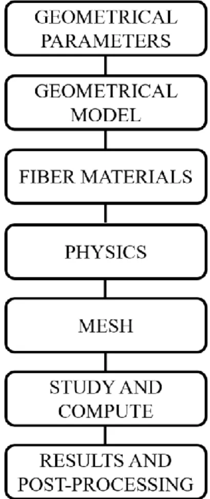
Figure 2.1. Workflow for modelling optical fibers in COMSOL Multiphysics. ... 33
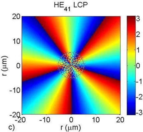
Figure 2.2. Polarization decomposition of the OAM mode HEe41+jHEo41 in ACF with Rb = 8 μm, Ra = 6 μm. a) Normalized electrical field intensity of the RCP (s = +1) and LCP (s = -1) contents; b) phase front of the RCP content, l = +3; c) phase front of the LCP content, l = +5. ... 37
Figure 2.3. a) OAM purity and δneff as a function of the OAM order l for Ra = 6 μm and Rb = 8 μm; b) OAM purity and δneff for l = 3 with respect to the ring thickness η = Ra/ Rb, Rb is fixed to 8 μm; c) OAM purity and δneff for l = 3 with respect to the outer ring radius Rb, η is fixed to 0.7. ... 39
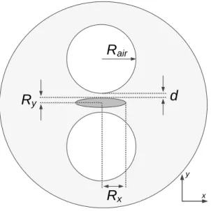
Figure 2.4. Schematic of the fiber cross section with the parameter definitions of the proposed air-hole assisted highly elliptical core fiber (dimensions are not to scale). ... 42
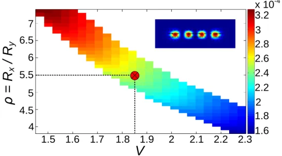
Figure 2.5. Minimum δneff as a function of V and ρ for fibers supporting 10 vector modes. Inset: TE14 intensity mode profile. ... 43
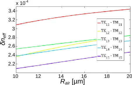
Figure 2.6. Birefringence δneff between TE1n and TM1n modes as a function of the air-hole radius, Rair. ... 44
Figure 2.7. (a) Effective mode index, neff, and (b) δneff, and Δneff between TM11 and TE12, both as a function of the holes-core distance, d. ... 45
Figure 2.8. (a) δneff, and Δneff between TM11 and TE12, and (b) chromatic dispersion, D, as a function of wavelength. ... 46
Figure 3.1. Cross sections of a: (a) highly elliptical core fiber, and (b) rectangular core fiber. The shaded areas are the fiber cores made of GeO2-doped silica. ... 54
Figure 3.2. Effective Index difference between the adjacent spatial modes for the two fiber designs: elliptical core (blue circle) and rectangular core (red square). The parameters of the fibers are listed in Table 4.1. ... 55
Figure 3.3. Geometry and parameter definitions of the highly elliptical core fiber
xii
(along the long axis). The inner ellipse fiber core is made of GeO2
-doped silica while the outer one is the depressed index trench made of F-doped silica. Dx and Dy are the core dimensions. ... 56
Figure 3.4. Minimum Δneff of the elliptical core fiber as a function of core width
and height with Δn = 1.1×10⁻². The colored region is where the fiber supports 10 vector modes (w = 4.6 µm, Δntrench = -5.6×10⁻³). The two
black dotted lines represent the two bending loss criteria proposed for SMF [127] for the last guided mode (first criterion) and the first leaky mode (second criterion). ... 57
Figure 3.5. Simulated mode intensity profiles of the elliptical core fiber with trench.
The modes are labeled as TE1n and TM1n depending on their
polarization (x and y). Fiber parameters: Dx = 31.5 µm, Dy = 6.1 µm,
Δn = 1.110-2, w = 4.6 µm and Δn
trench = -5.610-3. ... 57
Figure 3.6. Calculated bending loss, when bending the fiber around an axis parallel
to the y-axis, and when sweeping the trench width and depth for: (a) the last guided mode (i.e., the 10th mode, first criterion), and (b) first leaky mode (i.e., the 11th mode, second criterion). The red square
represents the trench parameters of the designed highly elliptical core fiber. ... 58
Figure 3.7. Properties of the designed highly elliptical core fiber calculated over
the C-band: (a) effective index neff, (b) effective index difference Δneff,
and (c) chromatic dispersion D [ps/nm*km]. ... 61
Figure 3.8. Δneff (open markers) and δneff (filled markers) of two fibers with highly
elliptical core designed to support 8 spatial channels, each with two polarizations: the first one has a larger Dx (red markers) and the second
one a higher Δn (blue markers). ... 63
Figure 4.1. (a) Cross section of the designed HECF [131], and (b) the measured
index profile of fabricated HECF. ... 69
Figure 4.2. (a) Measured reflection spectrum of a FBG written in the HECF. The
simulated Bragg wavelengths of each spatial mode are indicated by vertical dotted lines. Peaks and line colors are blue for TE, red for TM, and black for cross-coupling between spatial modes. Transmission spectrum of (b) second order modes, TE12 and TM12, and (c) fourth
order modes, TE14 and TM14. ... 72
Figure 4.3. Experimental setup used for the HECF characterization: (a) detection
setup for observing the FBG transmission spectrum, and (b) detection setup for observing mode stability in a 5 m HECF. ... 74
Figure 4.4. Experimental setup for the transmission of two QPSK signals over the
two orthogonal polarizations of the same spatial mode. Inset: Fiber cross section and mode intensity profiles. ... 76
Figure 4.5. (a) BER vs. OSNR when sending one polarization only and when
sending both polarizations of the same spatial mode at 24 Gbaud; (b) BER vs. baud rate at OSNR of 24 dB. ... 77
xiii
Figure 5.1. Experimental setup for measuring the MDL of a fiber under test (FUT).
ASE: amplified spontaneous emission; MZM: Mach-Zehnder modulator; PBS: polarizing beam splitter; SLM: spatial light modulator; PD: photodetector; HWP: half wave plate; QWP: quarter wave plate; MMF: multi-mode fiber; VNA: vector network analyzer. Inset: Refractive index profile of the fiber under test as reported in [81]. ... 85
Figure 5.2. FFT of the microwave interference pattern measured by the VNA when
exciting the fundamental mode (HE11) only. The extinction ratio of the
higher order mode group is higher than 25 dB. ... 87
Figure 5.3. FFT of the microwave interference pattern for a fiber length of (a) 634
m, and (b) 210 m. Left inset figure (a): zoom-in of the peaks TM01,
HE21 and TE01. Right inset figure (a): zoom-in of the peaks HE31 and
EH11. ... 87
Figure 5.4. Mode loss measurement error (dB/km) of the cutback technique as a
function of the mode loss η2, for different values of the input extinction ratio (EXT1). ... 90
Figure 5.5. Mode loss measurement error (dB/km) of the MICT as a function of
xiv
List of Abbreviations
ACF Air-core fiber
ASE Amplified spontaneous emission BER Bit error rate
BL Bending loss
COPL Centre d’optique, photonique et laser D Chromatic dispersion
DC Data center
DD-LMS Decision-directed least mean squares DMGD Differential mode group delay DSP Digital signal processing EDFA Erbium-doped fiber amplifier ER Extinction ratio
ERCF Elliptical ring-core fiber FBG Fiber Bragg grating FEC Forward error correction FEM Finite element method FMF Few-mode fiber FUT Fiber under test
HECF Highly elliptical core fiber HWP Half-wave plate
IPGIF Inverse parabolic graded-index fiber ISI Inter-symbol interference
xv
LCP Left circular polarization LP Linearly polarized
LPV Linearly polarized vectorial MCF Multicore fiber
MC-FMF Multicore few-mode fiber MC-MMF Multicore multimode fiber
MCVD Modified chemical vapor deposition MDL Mode dependent loss
MICT Microwave interferometric characterization technique MIMO Multiple-input multiple-output
MMF Multimode fiber
MPLC Multi-plane light conversion MZM Mach-Zehnder modulator NRZ Non-return-to-zero
OAM Orbital angular momentum OOK On-off-keying
OSA Optical spectrum analyzer OSNR Optical signal to noise ratio OV Optical vortices
OVA Optical vector analyzer PBS Polarization beam splitter PD Photodetector
xvi
PMF Polarization maintaining fiber QAM Quadrature amplitude modulation QPSK Quadrature phase shift keying QWP Quarter wave plate
RCF Ring-core fiber
RCP Right circular polarization RF Radio frequency
RoF Radio-over-fiber RTO Real-time oscilloscope SAM Spin angular momentum SDM Space division multiplexing SE Spectral efficiency
SLM Spatial light modulator SMF Single mode fiber SNR Signal to noise ratio
TDM Time division multiplexing TSA Thermal stress analysis UV Ultraviolet
VNA Vector network analyzer
xvii
Dedicated to my son, Tommaso. Thanks for making me dad.
xviii
Acknowledgements
There are many aspects that allow to a student to obtain a Doctor of Philosophy. Curiosity, innovation, motivation, and a stimulating work environment are only some of them. However, the people around us represent an important part during a Ph.D. journey. Here I would like to spend few words to the professors, colleagues and friends that helped and supported me in these four years abroad.
First of all, I have to express my deep and sincere thanks to Professor Sophie LaRochelle, supervisor of my Ph.D. project. Since the first day I spoke with her, when she interviewed me, she demonstrated her great professionalism and the desire to have me on board in her excellent research group. In these four years, her passion and enthusiasm for science guided and inspired me to investigate new fiber design solutions for the space division multiplexing. I am honored to have spent these years under her mentoring.
Secondly, I would like to thank Professor Leslie Ann Rusch, co-supervisor of my Ph.D. project. She was always opened to counsel me the right word to say, and her suggestions had a significant impact for my research. It was a great pleasure to discuss with her about the project, but especially about the Italian culture.
I cannot forget to thank the person who made this experience possible, Professor Gabriella Cincotti. She was the bridge between Canada and me, without her I would have not been able to pursue this career achievement. Even though four years have passed, she was always present during my experience even by hosting me in her offices in the last part of my doctorate. She has my deep and sincere gratitude.
Now it is time to thank the friends and colleagues that I met during my experience abroad. First of all, I would like to thank the two postdocs who were crucial for my research: Dr. Lixian Wang and Dr. Jun Ho Chang. Their suggestions, ideas, and solutions had a considerable impact in my works. It was a honor to work side by side with them. Then, I would like to thank my colleagues who became immediately great friends. They deserve to be named in this thesis without no order of importance: Omid Jafari, Rizan Homayoun Nejad, Reza Mirzaei Nejad, Sasan Zhalehpour, Mingyang Lyu, Gabriel Lachance, Antoine Gervais, and Charles Matte-Breton. Thank you, guys, for your friendship. I hope to meet you again.
xix
Finally, I would like to thank the engine of my life, the people who always had my back, ready to hold me up when I feel like falling. There are no words that I can spend here to repay for your love, but in my humble way I will try. To my family, my dad and my mum, I thank you for being a great source of inspiration, to motivate me, to support me, to be always present. You were always there, without no fear for the long trip to carry the fuel for my engine. If I have to think of greater parents, I think of you.
In Italy we use to say that best things are left at the end, so this is your time honey. We began this experience together, side by side. In the bad times, you were there to support me and let me see things in a different way. Your love is constantly inspiring me and motivating me to give my best. I thank you for choosing me as your husband and I thank you for donating me the greatest gift a man can wish in his life, a son. He is the fruit of our love, and also the fruit of this experience. One day we will tell him everything.
xx
Foreword
Three chapters of this thesis are reproductions of conference and journal papers, that were peer-reviewed, accepted and published. I am the first author of those papers, that were supervised by Professor Sophie LaRochelle and Professor Leslie Ann Rusch. Follows below my contributions to these works.
Chapter 3 is a reproduction of the following paper published in IEEE Photonics Journal.
A. Corsi, J. H. Chang, L. A. Rusch and S. LaRochelle, “Design of Highly Elliptical Core
Ten-Mode Fiber for Space Division Multiplexing With 2×2 MIMO,” IEEE Photonics
Journal, vol. 11, no. 2, 2019.
My contributions to this article are the following:
a) The design of a highly elliptical core fiber (HECF) surrounded by a depressed index trench. The goal of this design is to increase the effective index of the spatial modes in order to reduce the MIMO processing.
b) Performance comparison of this new design with the previously proposed rectangular core fiber through numerical evaluation.
c) Optimization of the fiber core dimensions in order to increase the effective index difference between the spatial modes, and optimization of the trench dimensions in order to decrease the bending loss of the higher order modes.
d) The writing of the paper and the answering to the reviewers’ comments.
Jun Ho Chang, the postdoc assigned to this project, assisted me in the simulation of the proposed few-mode fiber. In particular, we continuously discussed how to improve the geometrical parameters of the fiber core. Leslie Ann Rusch, co-supervisor of the project, provided guidance on the use of DSP processing for this type of fiber. Sophie LaRochelle, supervisor of the project, provided overall guidance and analysis of the results. All the co-authors of this paper revised the paper before publication.
Chapter 4 is a reproduction of two papers, one journal and one conference. The journal paper was published in the Optics Letters, while the conference paper was presented at the CLEO conference.
xxi
A. Corsi, J. H. Chang, R. Wang, L. Wang, L. A. Rusch and S. LaRochelle,
“Highly-elliptical-core fiber with stress-induced birefringence for mode multiplexing,” Optics
Letters, vol. 45, no. 10, pp. 2822-2825, 2020.
A. Corsi, J. H. Chang, S. Johnson, S. Zhalehpour, L. A. Rusch, and S. LaRochelle,
“Two-channels data transmission on a polarization-maintaining highly elliptical core fiber without MIMO,” Conference on Lasers and Electro-Optics (CLEO), 2020.
My contributions to these articles are the following:
a) Alignment of the optical worktable, including the free-space components, such as mirrors, half wave plates (HWPs), linear polarizer, and the spatial light modulator (SLM), for both the fiber characterization and the data transmission.
b) Experimental characterization of the fiber in terms of effective index difference between polarization and spatial modes, and mode stability (polarization extinction ratio (PER) and power fluctuations).
c) Numerical investigation of the thermal stress induced during the fabrication process. Comparison and validation of the experimental results with the simulated results.
d) Extrapolate BER performance from the data transmission experiment. e) The writing of the paper and the answering to the reviewers’ comments.
Jun Ho Chang, the postdoc assigned to this project, assisted me with the preparation of the experimental setup for the characterization and data transmission over the proposed fiber. Lixian Wang, an employee of Huawei (our industrial partner), provided fruitful discussion for the fiber characterization. The postdoc Ruohui Wang wrote the Bragg grating along the fiber in order to measure the fiber effective index. The postdoc Stanley Johnson, together with the PhD student Sasan Zhalehpour assisted me with the data transmission experiment, including the DSP processing and the analysis of the results. Leslie Ann Rusch, co-supervisor of the project, provided fruitful discussions for the analysis of the results regarding the DSP processing. Sophie LaRochelle, supervisor of the project, provided overall guidance and analysis of the results. All the co-authors of these papers revised the paper before publication.
xxii
Chapter 5 is a reproduction of the following paper published in IEEE Photonics Technology Letters.
A. Corsi, L. Wang, L. A. Rusch and S. LaRochelle, “Mode Loss Measurement in
Few-Mode Fibers with a Microwave Interferometric Technique,” IEEE Photonics Technology
Letters, vol. 30, no. 6, pp. 581-584, 2018.
My contributions to this article are the following:
a) Alignment of the optical worktable, including mirrors, half wave plate (HWP), quarter wave plate (QWP), spatial light modulator (SLM), and 3-axis stages. b) Experimental measurement of the mode dependent loss (MDL).
c) Development of the equations to calculate the MDL. d) Analysis of the results and discussion.
e) The writing of the paper and the answering to the reviewers’ comments.
Lixian Wang, the postdoc assigned to this project, assisted me during the experiment with useful suggestions and ideas. Leslie Ann Rusch, co-supervisor of the project, provided fruitful discussions for the analysis of the results. Sophie LaRochelle, supervisor of the project, provided overall guidance and analysis of the results. All the co-authors of this paper revised the paper before publication.
1
2
I.1 Capacity limit of optical fibers
The development of single mode optical fibers in the last decades has driven the revolution of the optical communications to the point that nowadays the whole Internet backbone is wired with optical systems, and the optical fiber is replacing the widespread coaxial cable, offering several advantages such as lower attenuation, higher amount of traffic, lower costs of fabrication and installation, since the optical fibers are lighter and thinner than coaxial cables. During the last decades, the capacity of the fiber transmission system has always met the exponential growth of the global Internet traffic, mainly created by social networking, cloud computing, and video services, such as YouTube, everyone requiring a large amount of bandwidth. To accommodate this Internet data traffic growth, several technological discoveries have allowed the transmission capacity of a single mode fiber to increase by a factor of approximately 10 every four years [1]. In the 1980’s, the reduction in the fiber losses (~0.2 dB/km) provided the first push in the fiber transmission capacity [2]. However, although the attenuation for the pure silica was the lowest possible at the near infrared wavelength (1550 nm), the losses were a crucial issue for the long-range optical links. To solve this problem, in the 1990’s, the invention of the erbium-doped fiber amplifier (EDFA) [3] in combination with the development of the wavelength division multiplexing (WDM) [4] resulted in one of the biggest fiber capacity jumps in the history of optical communications. The EDFAs provided the solution to remove expensive repeaters for signal regeneration, and they enabled the development of the WDM, which allowed to divide the bandwidth in multiple, independent and spectrally distinct wavelength channels, where the use of different carrier frequencies allows transmission of multiple communication signals over the same transmission medium. Throughout the 2000s, the introduction of advanced signal modulation formats and the use of coherent detection, combined with powerful digital signal processing (DSP) techniques to compensate for linear transmission impairments, provided the last jump in the fiber transmission capacity [5]. Most recently, it was proposed to double the channel capacity by using the two orthogonal polarization of the SMF. This strategy is denoted as polarization division multiplexing (PDM) [6]. Figure I.1 shows the fiber transmission capacity evolution during the years, showing how the technological discoveries, discussed before, have provided to this continuous evolution [7].
3
Figure I.1. Data transmission capacity of fiber transmission systems as a function of year [7].
Despite the fact that, in the last decades, the capacity of a single mode fiber grew together with the Internet traffic demand, research has found that we will be facing fundamental physical limitations due to the nonlinear nature of the medium [8]. According to the Shannon definition for the capacity of a channel [9], we can characterize a channel by introducing the spectral efficiency (SE) (or bandwidth efficiency). The SE is defined as the maximum amount of information (bit-rate) that can be transmitted over a given bandwidth, and it is measured in terms of bits per second per Hertz (b/s/Hz). As stated by Shannon in his work [9], for channels with linear additive noise, the SE scales logarithmically with respect to the signal-to-noise ratio (SNR), i.e., SE= log2(1+SNR).
From this relation, we can assume that increasing the signal power, leads to the SE performance increasing accordingly. However, increasing the signal power is not so obvious when working with optical fibers. Since they are a nonlinear medium, when the signal power increases, nonlinear effects will occur, degrading the SE [8]. Moreover, recent studies [10] have revealed that this SE degradation increases with the fiber length, as indicated in Figure I.2. This theoretical limit on the SE is better known as the nonlinear Shannon limit, and it depends on the transmission distance.
4
Figure I.2. Nonlinear capacity curves for a range of transmission distances [10]. The capacity of the optical fiber, in addition to being proportional to the SE, scales linearly with the effective transmission bandwidth B. However, the available bandwidth is not infinite and we suffer from bandwidth limitation of the optical amplifier [11]. If no alternatives are found, a “capacity crunch” of our system technologies is expected [1]. To scale the fiber transmission capacity, and consequently overcome this forthcoming capacity crunch, further innovations and breakthroughs in fiber designs and in multiplexing techniques are urgently required.
Nowadays, we are able to orthogonally multiplex optical data in different physical dimensions, as time (time division multiplexing, TDM), wavelength (wavelength division multiplexing, WDM), polarization (polarization division multiplexing, PDM) and phase (quadrature). All those dimensions are optimally handled. However, among all these physical dimensions to multiplex optical data, one dimension has been left unexplored until a few years ago: the space. The multiplexing technique behind the space dimension has been named: space division multiplexing (SDM).
I.2 Space division multiplexing
Space division multiplexing is currently under investigation, because it seems to provide the next big jump in the fiber transmission capacity needed to overcome the imminent capacity crunch, discussed earlier, as indicated in Figure I.1. Moreover, the key advantage of SDM is its compatibility with the WDM and with the advanced modulation formats,
5
such as quadrature phase shift keying (QPSK) or quadrature amplitude modulation (QAM).
The basic concept behind SDM is to use different spatial channels in the same fiber structure or fiber arrangement to increase the capacity of the optical transmission link. If we consider N independent channels carrying different information data, the SMF capacity is multiplied by a factor of N. The concept of SDM was firstly adopted to refer to multiple SMFs (between tens and hundreds of SMFs) packed together, to create what was referred to as fiber bundle or ribbon cable. This definition is still used in submarine optical communications, where the submarine cables host several optical fiber pairs to multiply the capacity of a single link. Although this is a rough method and the most obvious form of SDM, it is not the best solution in terms of costs of implementation (multiple devices at the fiber ends), space, and energy saving [12]. With this approach, the capacity crunch problem can only be alleviated but not solved. The best solution to reduce the costs and the energy consumption is the sharing of components in an optical transmission link. In optical communications, the term SDM refers to multiplexing techniques, where multiple spatially-parallel data paths are established through a single fiber. These paths can be composed by multiple cores, as in the case of multicore fibers (MCFs) [13], or by different modes, as in the case of multimode fibers (MMFs) [14] or few-mode fibers (FMFs) [15], or by a combination of both multiple cores and multiple modes (MC-MMF [16] and MC-FMF [17]).
I.1.1 Optical fibers for SDM
The concept of using multicore and multimode fibers, to multiplex optical data in space dimension, is not a recent idea. In 1979 [18], the first MCF was reported, while in 1982 [19], the first MMF. Only the urgent request to manage the upcoming capacity crunch in the fiber transmission capacity has unearthed these works and it has given birth to the concept of space division multiplexing. Figure I.3 shows the different approaches for realizing SDM discussed previously. In particular, the number of spatial modes guided inside the fiber depends on the size of the core area. The core size is related the normalized frequency, V, which determines the number of guided modes in the fiber [20]. A larger core area will include more modes. When the number of spatial modes supported by the fiber is between 2 and ~ 10, we will talk about few-mode fiber (FMF), whereas for a
6
higher number of spatial modes, typically hundreds of modes, we will talk about multimode fiber (MMF).
Figure I.3. Different approaches for realizing SDM.
Both strategies, MCF and MMF (or FMF), suffer from coupling between the different cores in the case of MCF, and between the different modes in the case of MMF, during the transmission. The coupling is due to inner fiber imperfections caused during the fabrication, as for example index inhomogeneities, or to external perturbations along the fiber, as for example bends or strain, which break the fiber symmetry and induce interactions between the different fiber cores or the different propagation modes. In both cases, the crosstalk can be mitigated and the data can be successfully received by making use of complex digital signal processing (DSP) based on the principle of multiple-input multiple-output (MIMO). The idea of MIMO technique is coming from the wireless communications, where multiple antennas at both the transmission and receiving sides are exploited in order to improve the link performance [21].
I.1.2 Devices and subsystems for SDM
Research over SDM includes not only the medium to transport information data, i.e., the optical fiber, but includes efforts in finding solutions for other optical components, such as spatial multiplexer and demultiplexer, amplifiers, filters, and switches, since the
7
proposed SDM fibers are not compatible with standard SMF systems and components. If we want to make the SDM a reality for our commercial optical communication technologies, we need to build an entire SDM transmission system around the SDM fibers [22].
Compact and low-loss spatial multiplexers and demultiplexers are extremely important for any SDM application, and attention has to be paid to the insertion losses and mode crosstalk added by those devices, since they become significant when considering higher number of multiplexed modes. For the case of FMF, free-space multiplexers are composed of phase plates [23] or spatial light modulators (SLMs) [24] which are mode-selective devices able to generate, in free-space and at the fiber input facet, mode profiles with intensity and phase distributions targeting the supported fiber modes. In particular, the SLMs offer the advantage of being reconfigurable in contrast to the phase plates, which is a crucial aspect in terms of mode pattern optimization. Multi-plane light converters based on reflective phase plates represent a valid proposal for SDM multiplexers, for their ability to excite a higher number of modes and for their low insertion loss [25]. Fiber-based solutions are another alternative for SDM multiplexers and demultiplexers. Photonic lanterns, for example, can generate a multiple set of high-order modes by means of an adiabatic fiber taper [26]. In particular, the idea of photonic lantern was originally proposed for astrophotonics [27], and then it was applied for optical communications. All-fiber photonic lanterns offer advantages in terms of low insertion loss, low mode dependent loss (MDL) and high temporal stability. Another fiber-based solution for SDM multiplexers is represented by mode selective couplers [28]. They consist in SMF tapered to specialty designed SDM fiber, and the mode-selective functionality of the coupler is achieved via matching of the modal propagation constants, by precisely control of the taper ratio of the fibers during the fabrication. Finally, integrated silicon devices represent a compact and promising alternative for SDM multiplexers [29].
Looking at long-haul SDM applications, fiber amplification is a critical aspect since we need to compensate for the signal attenuation resulting from the propagation inside the fiber for a long transmission distance. The goal is to amplify all the multiple spatial channels by using multicore or multimode EDFAs. This allows to reduce the space, the power consumption, and the number of optical devices, compared to the case of using single-mode EDFAs to amplify every single spatial channel. The development of SDM
8
amplifiers is around the corner, either core-pumped [30] or cladding-pumped [31]. In the core-pumped strategy, there is the advantage to amplify every single core individually and have a more controlled system. On the other hand, the cladding-pumped strategy offers the advantage to decrease the costs, the power consumption and the required space.
I.3 Objective and thesis outline
Increasing the capacity of a single-core fiber represents an imminent problem to overcome the incumbent capacity crunch of our transmission systems. New specially designed fibers, afar from the common circular fiber core structures, need to be explored. This thesis has the objective to investigate a new FMF for MIMO-free systems, and to provide a method to characterize FMF fibers in terms of mode dependent loss (MDL). In particular, the project is focused on fiber design solution for unamplified short reach link without MIMO. In order to accomplish the PhD. project objectives, this thesis is organized into the following chapters.
Chapter 1 is dedicated to mode division multiplexing (MDM) strategies. It gives an overview of previous works dedicated to the MDM over the last years. In particular, we focus on the possible scenario for transmission over truly orthogonal modes guided in the fiber, including linearly polarized (LP) modes, the orbital angular momentum (OAM) modes, and, finally, the vector modes. We compare all those works in terms of proposed fiber design, number of modes, MIMO complexity and data transmission experiments. Chapter 2 gives an overview on the optical fiber modelling performed with the numerical solvers of COMSOL Multiphysics. Starting from the definition of the geometrical model, we pass through the explanation of all the modelling steps required to simulate optical fibers, such as the definition of the fiber materials and the physics, but also the generation of the meshes, and, finally, the results and post-processing steps. We also include two separate works where this optical fiber modelling was implemented.
Chapter 3 discusses the design of a new proposed FMF that consists of a highly elliptical core, able to support five spatial modes with twofold polarization degeneracy (ten channels). Simulations predict an effective index difference between the spatial modes higher than 1×10⁻³ over the C-band. This highly elliptical core fiber (HECF) also includes a depressed index trench surrounding the core, added to decrease the bending loss of the higher order modes. Moreover, we perform numerical simulations to optimize the fiber
9
core size in terms of effective index difference, and the trench dimensions in terms of bending loss.
Chapter 4 first discusses the characterization of the proposed HECF. In particular, the experimental characterization revealed the polarization maintaining properties of the fiber. In addition to the asymmetric core structure, the birefringence of the fiber is increased by the thermal stress introduced during the fabrication. We experimentally measured the fiber birefringence with a fiber Bragg grating (FBG) technique, and we included the thermal stress in our fiber modelling. We found a good agreement between the simulated and measured effective index difference between all the eigenmodes, with values for the birefringence higher than 1.3×10⁻⁴. This level of modal birefringence
should be sufficient to reduce mode coupling between different polarizations and allow MIMO-free transmission over short data links. We therefore performed a first data transmission experiment with the HECF, by transmitting two QPSK signals over the two polarizations of each spatial mode, without the use of any MIMO processing.
Chapter 5 discusses a new method to characterize FMFs in order to extract the mode dependent loss (MDL) of the fiber. This method aims to extend a microwave interferometric characterization technique (MICT), previously proposed to measure the differential mode group delay (DMGD) between the FMF modes, to the computation of the MDL of mode groups. The calculation of the MDL, is based on the measured interference pattern of the microwave signals carried by the various modes, for two different fiber length (one longer than the other one). We discuss the mathematical steps to reach the equation for measuring the MDL, and we discuss the experimental results to measure the MDL of a specialty designed FMF.
Conclusions and perspectives include the final thoughts of this research.
In addition to the above mentioned work, as part of the doctorate studies, the thesis author participated and contributed to other works related to the design, characterization and transmission of other specialty designed fibers. The complete list of publications follows below.
[I] A. Corsi, L. Wang, L. A. Rusch and S. LaRochelle, “Mode Loss Measurement in Few-Mode Fibers with a Microwave Interferometric Technique,” in IEEE
10
[II] A. Corsi, J. H. Chang, L. A. Rusch and S. LaRochelle, “Design of a Ten-Mode Polarization-Maintaining Few-Mode Fiber for MIMO-Less Data Transmission,” in
European Conference on Optical Communication (ECOC), 2018.
[III] A. Corsi, J. H. Chang, L. A. Rusch and S. LaRochelle, “Design of Highly Elliptical Core Ten-Mode Fiber for Space Division Multiplexing With 2×2 MIMO,” in IEEE
Photonics Journal, vol. 11, no. 2, 2019.
[IV] A. Corsi, J. H. Chang, R. Wang, L. Wang, L. A. Rusch and S. LaRochelle, “Highly-elliptical-core fiber with stress-induced birefringence for mode multiplexing,” in
Optics Letters, vol. 45, no. 10, pp. 2822-2825, 2020.
[V] A. Corsi, J. H. Chang, S. Johnson, S. Zhalehpour, L. A. Rusch, and S. LaRochelle, “Two-channels data transmission on a polarization-maintaining highly elliptical core fiber without MIMO,” in Conference on Lasers and Electro-Optics (CLEO), 2020.
[VI] L. Wang, A. Corsi, L. A. Rusch and S. LaRochelle, “Investigation of orbital angular momentum mode putiry in air-core fibers,” in IEEE Photonics Society Summer
Topical Meeting Series (SUM), 2016.
[VII] L. Wang, R. M. Nejad, A. Corsi, J. Lin, Y. Messaddeq, L. A. Rusch and S. LaRochelle, “MIMO-free transmission over six vector modes in a polarization maintaining elliptical ring core fiber,” in Optical Fiber Communications
Conference and Exhibition (OFC), paper Tu2J.2, 2017.
[VIII] L. Wang, R. M. Nejad, A. Corsi, J. Lin, Y. Messaddeq, L. A. Rusch and S. LaRochelle, “Linearly polarized vector modes: enabling MIMO-free mode-division multiplexing”, in Optics Express, vol. 25, no. 10, pp. 11736-11748, 2017.
[IX] S. LaRochelle, A. Corsi, R. M. Nejad, L. Wang, X. Guan, J. H. Chang, J. Lin and L. A. Rusch, “Optical fiber designs for MIMO-less SDM,” in Conference on Lasers
and Electro-Optics (CLEO), paper SW3K.5, 2018.
[X] S. LaRochelle, A. Corsi, J. H. Chang, L. A. Rusch, and Y. Messaddeq, “Polarization maintaining few mode fibers for space division multiplexing,” in CLEO Pacific Rim
Conference, paper F2F.1, 2018.
[XI] J. H. Chang, A. Corsi, L. A. Rusch, and S. LaRochelle, “Design Analysis of OAM Fibers using Particle Swarm Optimization Algorithm,” in IEEE Journal of
11
Chapter 1
12
1.1 Introduction
As discussed in the previous chapter, mode division multiplexing (MDM) represents a valid solution to multiplex the information data in the space dimension, and consequently overcome the imminent ʻcapacity crunchʼ of our system technologies. In particular, MDM can be achieved with multimode fibers (MMFs) or with few-mode fibers (FMFs), depending on the number of guided modes in the fiber. The key advantage of the MMFs is the possibility to excite, in the same fiber core, a higher number of modes (until hundreds of modes) than the widespread standard single-mode fibers (SMFs), where the information travels along its two channels (represented by the two orthogonal polarization states), and it does not give space for capacity improvement. This is made possible by the bigger core size of the MMFs compared to the standard 8 µm core diameter of the SMFs. A bigger core size allows also an easier coupling of the light inside the fiber, and the fabrication process is similar to the one of SMF, with the only exception that the core size is enlarged. However, MMFs had to face some obstacles, coming from the co-propagation of several modes inside the same transmission medium. When we couple light in a MMF, we excite a number of fiber modes, which will travel at different speeds inside the fiber. The fiber modes will consequently arrive at different times at the receiver. The delay between the different arrival times is better known as differential mode group delay (DMGD). A high value for the DMGD will cause a spreading of the transmitted signal, which will cause the so-called modal dispersion, and consequently inter-symbol interference (ISI) on the detection side. This will unavoidably limit the transmission rate of the MMFs and it will limit the distance over which these fibers can be used, making impossible the long-haul transmission (hundreds of kilometres). For these reasons, MMFs operate efficiently over short distances, typically tens of meters.
Because of DSP and Mux/DeMux limitations, researchers have focused their attention on the development of fiber supporting a small number of spatial modes, the so-called few-mode fibers (FMFs). FMFs have the same principle of MMFs, with the difference that the core size is adjusted to allow the propagation of a restricted number of spatial modes, typically between two and ten spatial modes. For long transmission links, the different optical paths will be coupled to each other, mainly because of inner fiber imperfections or external perturbations, such as fiber bend and strain. This will introduce a random exchange of energy between the guided spatial modes during the propagation inside the fiber. This coupling will cause crosstalk between the modes at the receiver side, i.e., a
13
signal transmitted on a certain mode is coupled to another mode along propagation causing spreading of the channel impulse response. The only way to mitigate these signal impairments is through the use of heavy multiple-input multiple-output (MIMO) digital signal processing (DSP) on the receiver side [32]. The MIMO technique, an idea coming from the wireless communications, is as follow: if we consider a system with N modes and two polarizations per mode, the MIMO processing will require 2N×2N equalizer blocks, with the task to undo the coupling, previously described, between the modes. The term ʻheavyʼ used to describe the MIMO-DSP is coming from the complex algorithms and the high power consumption required to implement it. Moreover, increasing the number of the N spatial modes will increase inevitably the DSP complexity, since the number of MIMO equalizers will scale accordingly, and consequently the energy consumption will be higher [33].
When talking about FMFs, there exist two different regimes: the strongly-coupled regime and the weakly-coupled regime. In the first regime, as the name indicates, the modes strongly couple to each other and the minimization of the differential mode group delays (DMGDs) allows to use complex 2N×2N MIMO equalizer blocks with a reasonable number of taps to untangle modal crosstalk. If the modes are spread over a large time interval, we will face a long impulse response and, consequently, a greater number of taps for the equalizers, increasing the complexity and the power consumption of the MIMO signal processing. The strongly-coupled regime is favourable for long distance transmissions, since under this condition mode coupling is unavoidable. Using 2N×2N MIMO-DSP to undo the modal crosstalk is a technique known with the name of full-MIMO. On the other hand, in the second regime, the attention is focused on the minimization of the mode coupling, so that the modes are ʻweakly coupledʼ to each other. In this case, the MIMO processing is applied only to compensate the intra-mode group coupling, because of the low inter-mode group coupling, which requires an effective index difference between mode groups higher than 1×10⁻³. For this reason, the MIMO-DSP consists of simple 2×2 (two-fold polarization degeneracy) and 4×4 MIMO (four-fold polarization and spatial degeneracy) equalizer blocks. The weakly-coupled regime is favourable for short-reach applications, such as data centers (DCs), since the coupling is directly proportional to the transmission distance. We refer to this technique as partial-MIMO, since the complexity of the MIMO-DSP is drastically decreased (it does not depend on the number of fiber modes). Both regimes require an accurate design of the
14
fiber index profile, minimizing the DMGDs for the strongly-coupled regime or on the mode coupling for the weakly-coupled regime. In particular, graded-index profile for the fiber core is an attractive solution for the strongly-coupled regime, while the step-index profile is more suitable for the weakly-coupled regime. However, both regimes have their own drawbacks, because in the strongly-coupled regime, the complexity of the MIMO scales with the number of modes, while, on the other side, in the weakly-coupled regime, a careful design of all the transmission line elements is required in order to reduce the mode coupling.
In this chapter, we review the different modal basis that can be used in MDM systems, such as linearly polarized (LP) modes, orbital angular momentum (OAM) modes, and vector modes. We then review all recent progress in fiber design and fiber transmission over FMFs, that make use of those modes, and we compare the fiber designs, the number of guided modes, the MIMO complexity, and the data transmission experiment results.
1.2 Linearly polarized mode groups
When the refractive index difference between the core and the cladding of an optical fiber is small, we are under the so-called ʻweakly guiding conditionʼ, and the fiber eigenmodes are grouped into linearly polarized (LP) modes. The LPkm modes, where k is the azimuthal
order and m is the radial order, are typically used during experiments, since they are more readily excited and detected. LPkm modes are linear combinations of the fiber vector
modes HEk,m and EHk,m. For the vector mode HE, k is equal to ν+1, while for the vector
mode EH, k is equal to ν-1. For ν = 0, we have only the vector mode HE11, with both the
x and y polarizations, and it is the fundamental mode of the fiber, which is always guided
in every optical fiber. The LP modes made by the two polarizations of the fundamental mode are referred as LP01, and they are characterized by an intensity profile similar to
that of a Gaussian beam. To give an example of LP modes, Figure 1.1 shows the different LP modes coming from the combination of the lowest order vector modes.
15
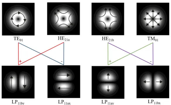
Figure 1.1. Combinations of vector modes to generate the 4-fold degenerate LP11 mode.
In general, the LPkm modes are four-time degenerate, i.e., they are composed by four
different LP modes, except for the order k = 0, which is only two-time degenerate. Inside every LPkm mode groups, the different LP modes, are distinguished by spatial and
polarization indices. The modes are labelled “a” or “b” depending on the orientation of the intensity profile and for each mode there are two possible polarization states, which will be labelled as “x” and “y”. Table 1.1 summarizes the different nomenclature for the modes in an optical fiber.
16
The vector modes that form the LP modes have distinct propagation constants, and different LP modes can share the same vector modes. This will inevitably cause a random coupling among different LP modes during the propagation inside the fiber, producing crosstalk at the receiver side. In order to undo this mode coupling, MIMO-DSP is required at the receiver side, increasing the system costs: complex algorithms and high power consumption.
1.2.1 Strongly coupled
During the recent past, several transmission experiments over LP modes of MMFs and FMFs were proposed, including strongly-coupled and weakly-coupled strategies. For the strongly-coupled MMF, a trench-assisted graded-index core profile was demonstrated to support 2 LP modes [34], 4 LP modes [34, 35], 6 LP modes [36,37], and 9 LP modes [38]. A key feature in the design of this fiber relies on the choice of the graded-index profile in addition to a depressed cladding index profile (fluorine-doped trench). While the trench reduces the bending sensitivity, the graded-index profile minimizes the differential mode group delay (DMGD) between the modes, a characteristic that is required for a reasonable MIMO processing (lower equalizer memory length). Different data transmission experiments were performed with the fiber supporting 3 LP modes, i.e., the LP01 mode and the two-time degenerate LP11 modes (for a total of six spatial and
polarization modes). In [39], the authors reached a fiber length of 10 km, transmitting 28 Gb/s QPSK signal along the six spatial and polarization modes, using coherent 6×6 MIMO processing. The same experiment was extended to an even longer fiber length, i.e., 33 km [40]. With the same graded-index fiber, a 6×40 Gb/s QPSK signal transmission was demonstrated for a fiber length of 96 km [15]. All those demonstrations utilize a free-space setup, including common phase plates, having a phase jump of π between two planes, to excite the two-degenerate LP11 modes, and single-mode fiber (SMF) output
mode to excite the LP01 mode. In the years following those experiments, the development
of new highly-selective mode multiplexing devices, such as photonic lanterns [41] and multiplexers based on multi-plane light conversion [42,43], allow the transmission of a higher number of LP modes. In [44], a conventional 50 µm core diameter graded-index MMF was used to transmit 30 GBaud QPSK signal over six spatial modes for a 17 km long fiber. Authors used photonic lanterns as multiplexer and demultiplexer, and a coherent 12×12 MIMO signal processing to undo the coupling and receive correctly the modes. Another experiment utilizing the 12×12 MIMO-DSP was presented in [45], where
17
photonic lanterns were used to multiplex and demultiplex 12 mode FMF channels, in order to transmit 30 GBaud 16-QAM signals and 120 WDM channels over 650 km long fiber, reaching a transmission throughput of 138 Tbit/s. In [46,47], two different research groups demonstrated the transmission of ten LP modes (twenty spatial and polarization modes) by using a coherent 20×20 MIMO signal processing. Both studies utilized all fiber photonic lanterns, but the experiment in [46] used a 4.45 km fiber length to transmit 10 GBaud QPSK signals, while the experiment in [47] transmitted a 30 GBaud QPSK signals over a 125 km fiber length. Both experiments make use of mode selective photonic lantern multiplexer and demultiplexer, to excite and detect the fiber modes. Afterwards, the same authors of [46] increased the fiber length up to 40 km, by transmitting 10 GBaud signals over the 20 spatial channels (10 spatial modes with 2 polarizations) of a conventional 50 µm core diameter MMF, and using 10-port photonic lantern multiplexer and demultiplexer [48]. Moreover, 15-mode photonic lanterns were used to enable the transmission of 30 spatial and polarization modes along a 22.8 km fiber length. The fiber consists of a trench assisted graded-index fiber designed to support up to 9 LP modes (30 spatial and polarization modes), and, consequently, a full-MIMO processing with 30×30 equalizer blocks were used to transmit 30 GBaud QPSK signals [49]. Finally, the development of mode multiplexers based on the multi-plane light conversion (MPLC) principle [42,43] allows to reach a record transmission of 90 spatial channels (45 spatial modes with two polarizations) along a 26.5 km fiber long and using a coherent 90×90 MIMO signal processing [50]. All those studies make use of conventional 50 µm core diameter graded-index MMFs, optimized to have the minimum DMGD possible [51]. However, the MMF transmission experiments, described above, required heavy 2N×2N equalizer blocks (full-MIMO). The complexity of the MIMO processing, quantified in relation with the number of equalizers required for adequate modes reception, increases rapidly with the number of spatial channels [52]. This represents a crucial aspect, in terms of costs and energy consumption, in scaling the capacity of MDM systems.
1.2.2 Weakly coupled
An alternative approach for reducing the MIMO-DSP complexity is represented by the weakly-coupled FMF, where the reduction of the mode coupling is a key aspect. In this case, it is possible to divide the 2N×2N MIMO matrix into several MIMO blocks depending on the number of fiber mode groups. In this way, MIMO blocks with relatively
18
low dimensionality are utilized only for compensation of mode coupling within mode groups, as mode coupling between different mode groups is prevented by a large effective refractive index difference, Δneff, between the spatial modes. We define this strategy as
partial-MIMO. The mode coupling is strongly related to the effective index difference (Δneff) between adjacent LP modes in a inversely proportional relation [53], which
indicates that for a reduction of the mode coupling, and consequently no requirements for full-MIMO processing, a high value of Δneff is needed between the propagation modes
(typically is required Δneff > 1.0×10⁻³). A small number of modes in each of the well
separated mode groups are thus desirable to keep the dimensionality of MIMO blocks low. In this respect, graded-index circular-core fibers are not suitable for weakly-coupled FMF because at least two different LP spatial modes typically belong to the same mode group (except for LP01). For example, LP11a and LP11b form a degenerate mode group that
would require 4×4 MIMO equalizer blocks. Similarly, LP21 and LP02 modes in
graded-index fiber constitute a near-degenerate mode group that requires a block of 6×6 MIMO equalizers for mode demultiplexing. Step-index circular-core FMFs, designed to have a
Δneff >10-3 to minimize the mode coupling, have been used as weakly-coupled FMF,
characterization results is found in [54] and data transmission in [55, 56]. In [55], the authors demonstrate a 100 Gb/s PDM-QPSK signal transmission over five LP modes (LP01, LP11a, LP11b, LP21a, and LP21b) of a 40km long FMF. The multiplexer and
demultiplexer consist of free-space optics, where the modes are excited and detected with phase plates. The signals are recovered with one block of 2×2 MIMO equalizers for the LP01 mode and two blocks of 4×4 MIMO equalizers for the LP11 and LP21 mode groups.
Some years later, a ten-mode-multiplexed transmission of 12 GBaud dual-polarization (DP) QPSK signals over a 48 km weakly-coupled FMF was demonstrated with partial-MIMO-DSP, i.e., only two blocks of 2×2 MIMO equalizers for the LP01 and LP02 modes,
and four blocks of 4×4 MIMO equalizers for the LP11, LP21, LP31 and LP12 mode groups
[56]. A highly mode-selective 10-mode multiplexer based on multi-plane light conversion (MPLS) was used to excite and receive the fiber modes [57]. In particular, this work reaches a record fiber capacity of 257 Tbit/s for the single-core fiber transmission, making use of the C+L band (336 WDM channels). During the last few years, another weakly-coupled FMF approach was proposed for partial-MIMO, i.e., the ring-core fiber (RCF). The RCF can ensure a high effective index difference (Δneff) between two adjacent LP
modes, which significantly increases with increasing azimuthal number of LP modes for the same radial mode number [58]. The suppression of the LP modes with radial number
19
higher than 1 is mandatory to avoid coupling with the nearby LP modes with a radial number equal to 1 and with disparate azimuthally numbers. While the azimuthal number of propagation modes depends on radius and thickness of the ring layer, the radial number of propagation modes only depends on the thickness of the ring layer [59]. Moreover, RCFs present also a large effective area, which is beneficial for decreasing the nonlinear effects and the sensitivity to bending [60]. In addition, the spatial fiber modes show low attenuation [61]. A ring-core fiber with a graded-index core profile was demonstrated for large Δneff, for 7 LP mode groups [62], based on an accurate study of the RCF design [63],
which showed that small ring radius and large thickness for the RCF are necessary for a large Δneff between the propagation modes. This graded-index RCF showed an effective
index difference (Δneff) between the low-order modes significantly smaller than the Δneff
between high-order modes. In this way, the low-order mode channels required only a low complexity MIMO processing, while high-order mode channels did not require any MIMO processing within a certain transmission distance. To further increase the capacity, MIMO processing can be applied in order to use the degenerate modes within a mode group. In [64], a 4 LP mode groups graded-index RCF was demonstrated for data transmission over 100 m without MIMO equalization. Authors transmitted 10 Gbps NRZ signals over two LP mode groups. In particular they choose two combinations of mode groups. The first is represented by the modes LP01 and LP21, while the second is
represented by the modes LP01 and LP21. The authors neglected the mode LP11 because
of the strong coupling with the adjacent LP01 mode. The multiplexer and demultiplexer
consisted of programmable and reconfigurable spatial light modulator (SLM). The same authors demonstrated, one year later, the possibility to use RCF for a relatively long fiber distance (24 km) [65]. In particular, the authors transmitted 2×10 Gbit/s OOK signals with simple direct detection, by using the high order modes LP21 and LP31, because of
their higher separation in terms of Δneff than the low order modes LP01 and LP11.
However, the absence of MIMO processing was allowed because only mode groups were multiplexed and no PDM was implemented, reducing considerably the capacity of the system.
1.2.3 Mode group multiplexing over elliptical core fibers
In addition, MIMO-free approach has been proposed using elliptical core FMFs, where the ellipticity of the core is made by applying asymmetric stress. In 2015, the first data transmission experiment over an elliptical core FMF was demonstrated [66]. The
![Figure I.1. Data transmission capacity of fiber transmission systems as a function of year [7]](https://thumb-eu.123doks.com/thumbv2/123doknet/2886052.73537/26.892.133.764.105.474/figure-data-transmission-capacity-fiber-transmission-systems-function.webp)
![Figure 1.2. Helical phase fronts for: (a) l = 0, (b) l = 1, (c) l = 2, (d) l = 3 [71]](https://thumb-eu.123doks.com/thumbv2/123doknet/2886052.73537/44.892.233.662.436.778/figure-helical-phase-fronts-l-b-l-c.webp)
![Figure 1.3. The four possible OAM mode combinations [74].](https://thumb-eu.123doks.com/thumbv2/123doknet/2886052.73537/46.892.233.657.104.547/figure-possible-oam-mode-combinations.webp)