HAL Id: tel-01686531
https://pastel.archives-ouvertes.fr/tel-01686531
Submitted on 17 Jan 2018HAL is a multi-disciplinary open access archive for the deposit and dissemination of sci-entific research documents, whether they are pub-lished or not. The documents may come from teaching and research institutions in France or abroad, or from public or private research centers.
L’archive ouverte pluridisciplinaire HAL, est destinée au dépôt et à la diffusion de documents scientifiques de niveau recherche, publiés ou non, émanant des établissements d’enseignement et de recherche français ou étrangers, des laboratoires publics ou privés.
Photovoltaic devices
Rasha Khoury
To cite this version:
Rasha Khoury. Nanometer scale point contacting techniques for silicon Photovoltaic devices. Micro and nanotechnologies/Microelectronics. Université Paris Saclay (COmUE), 2017. English. �NNT : 2017SACLX070�. �tel-01686531�
NNT : 2017SACLX070
T
HESE DE DOCTORAT
DE
L’U
NIVERSITEP
ARIS-S
ACLAY PREPAREE AL’E
COLEP
OLYTECHNIQUEE
COLED
OCTORALE N°
573
Interface : approches interdisciplinaires, fondements, applications et innovation
Spécialité de doctorat : Physique
Par
Mme Rasha KHOURY
Nanometer scale point contacting techniques for silicon Photovoltaic devices
Thèse présentée et soutenue à Palaiseau, le : 20 Octobre 2017
Composition du Jury :
M. Thierry Gacoin Directeur de Recherche, CNRS, PMC Ecole Polytechnique Président M. Sébastien Dubois Ingénieur de Recherche, INES-CEA Rapporteur M. Bart Vermang Professeur,
University of Hasselt, Belgium
Rapporteur M. Ramon Alcubilla Professeur, UPC Barcelona, Spain Examinateur M. Stéphane Collin Chargé de Recherche, CNRS, C2N Université Paris-Sud Examinateur M. Erik V. Johnson Chargé de Recherche, CNRS, LPICM Ecole Polytechnique Directeur de thèseAbstract
In this PhD work, I explore the possibility and potential advantages of using nanoscale contact openings in the range of 1 µm or below and, consequently, with a pitch shorter than 10 µm. Indeed, analytic and numerical simulations done with and by our collaborators during the course of this thesis have shown that such nanoscale contacts would result in negligible ohmic losses while still keeping Seff,rear at an acceptable level, as long as the recombination velocity at the contact (Scont) is in the range from 103-105 cm/s. To achieve such contacts in a potentially cost-reducing way, my experimental work has focused on the use of polystyrene nanospheres as a sacrificial mask.
The thesis is therefore divided into three sections. In the first section, three deposition techniques (spray-coating, spin-(spray-coating, and a floating transfer technique) for particles were tested. The first two give poorly controlled distributions of nanospheres on the surface, but with appropriately low values of coverage. The floating transfer technique provided a densely-packed monolayer of NPs on the surface; this process necessitated an additional O2 plasma step to reduce the coverage area of the sphere; this was performed and studied using a matrix distributed electron cyclotron resonance (MD-ECR) plasma. The removal of the nanospheres after being coated by metals and dielectrics was also studied.
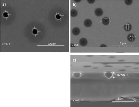
In the second section of this thesis, three different approaches were developed to generate local point contacts on metallic and crystalline silicon surfaces. The first uses the NPs as a direct deposition mask (Approach A), for example by dispersing NPs onto a layer, depositing SiO2 or Si3N4 by PECVD on top of the NPs, and then removing the NPs. The second is by depositing a secondary etching mask layer on top of the NPs. This was done with evaporated Al as a plasma-etching mask for thermally grown SiO2 (Approach B), and PECVD a-SiCx:H as a wet-etch mask for Al2O3 deposited by ALD (Approach C). I have tested nanoholes formed using approach A as point contacts on a NIP a-Si:H solar cell. Homogenously distributed nano-contacts less than 100 nm as diameter were obtained in the back-reflector layer with an average distance between the contacts of ~350 nm. The electrical characteristics of the nano contacted NIP a-Si:H were compared to the same cells done without the dielectric layer, and to a structure with a dielectric layer but without any nanoholes.
In the third section of this thesis, I investigate the use of such nanoholes in crystalline silicon technology by the formation of doped contacts through nanoholes formed by approach B. Boron doping by both thermal diffusion and ion implantation techniques were investigated. A thick thermally grown oxide was used as the diffusion/implantation barrier. Once the NPs and the secondary etch mask were removed, these samples were characterized by secondary electron microscopy (SEM) and conductive probe atomic force microscopy (CP-AFM). Localized doping was indeed observed through CP-AFM by acquiring current-voltage curves both within and beside the doped area, and nanoscale solar cells were observed. For the ion implantation samples, a Rapid Thermal Annealing step dramatically changed the appearance of the samples under SEM, and although diodes were formed, the process needs further refining to produce the same results as diffusion.
In summary, the work presented in this PhD manuscript has developed and explored a potentially low-cost technique of creating nano-scale openings for optoelectronic devices. A number of hole-creating techniques are developed, described, and deployed in test structures involving thin-film and crystalline silicon.
Keywords: Polystyrene Nanoparticles, Nanostructure, Doping, crystalline silicon, thin film, Conducting Probe Atomic Force Microscopy, Secondary electron microscopy.
List of acronyms
AFM: Atomic Force Microscopy
AlCu: Alloy of 98% Aluminum and 2% Copper ALD: Atomic Layer Deposition
a-Si:H: Hydrogenated Amorphous Silicon BSE: Backscattered Electrons
BOE: Buffered Oxide Etch
CCP: Capacitively Coupled Plasma CP-AFM: Conductive Probe AFM cSi: Crystalline Silicon
CVD: Chemical Vapor Deposition DI: Deionized
DLS: Dynamic Light Scattering ECR: Electron Cyclotron Resonance
ECV: Electro-Chemical Capacitance Voltage
FE-SEM: Field-Effect Scanning Electron Microscopy HF: Hydrofluoric Acid
ICP: Inductively Coupled Plasma ITO: Indium Tin Oxide
LTO: Low Temperature oxidation
MDECR: Matrix Distributed Electron Cyclotron Resonance NP: Nanoparticle
PECVD: Plasma Enhanced Chemical Vapor Deposition PERC: Passivated Emitter and Rear Cell
PERL: Passivated Emitter Rear Locally Diffused Cell PS: Polystyrene
PV: Photovoltaic
PVD: Physical Vapor Deposition RF: Radio Frequency
SE: Secondary Electron
SEM: Secondary Electron Microscopy SCM: Scanning Capacitance Microscopy SIMS: Secondary Ion Mass Spectrometry
SNDM: Scanning Nonlinear Dielectric Microscopy SPM: Scanning Probe Microscopy
SSRM: Scanning Spreading Resistance Microscopy TEM: Transmission Electron Microscopy
TMA: Trimethylaluminum TMB: Trimethylboron US: Ultrasonic
Acknowledgements
This PhD work of three years took place in two labs; LPICM at Ecole Polytechnique and MNT at Polytechnic University of Catalonia (UPC), where I spent around 9 months. I would like to thank the directors Pere Roca and Ramon Alcubilla for welcoming in their lab.
I am delighted to have defended my PhD in front of: Thierry Gacoin, Sébastien Dubois, Bart Vermang, Ramon Alcubilla, and Stéphane Collin. I would like to thank them for their presence, for the questions they
have asked, and for their contribution to this manuscript.
The completion of my doctoral work was possible with the support of several people. I would like to express my sincere gratitude to all of them.
First of all, I am extremely grateful to my supervisor Erik Johnson for his valuable guidance and consistent encouragement I received throughout the research work. I appreciate the freedom and confidence he provided me. He was always there to answer my questions and discuss whenever I needed.
I wish to express my sincerest gratitude to Pavel Bulkin who helped me in the experimental work. His knowledge in different scientific areas has made him as a continuous source of ideas which inspired and enriched my growth as a student and as a researcher. My gratitude is also extended to Dmitri Daineka who helped me as well with the experimental work, especially in the preparation of samples at Thales. I would like also to thank Nicolas Vaissiere for his help in the preparation of the samples related to epitaxial growth and Ronan Léal for the discussions related to this topic, without forgetting to thank Denis Tondelier for his help during my first year of PhD.
I would like to thank Li Zeyu from NTU Singapore, who helped in the Nanoparticles deposition and etching experiments during his mobility in LPICM, without forgetting the hours we spent taking SEM images and our discussions on many topics.
I extend my sincere thanks to all the researchers and PhD students at LPICM and TOTAL who I met during these three years, especially to my colleagues and friends with whom I shared the office (Karim Ouaras,
Jean-Maxime Orlach, Mengkoing Sreng, Anatole Togo, Billal Farryssy, Rim Boukhicha, and Linda Assam).
During my PhD, I had the chance to collaborate with GeePs at Supelec to do the electrical measurements of CP-AFM. I am deeply thankful for Jose Alvarez for all the measurements that he has done on my samples with the help of Tatsuya Ohashi. Jose was always there to answer my questions and to suggest interesting ideas. I would like as well to thank Jean Paul Kleider and Raphael Lachaume from GeePs.
The mobility that I have done at MNT group at UPC in Barcelona remains the best part of my PhD. I got the support of several people, for whom I would like to express my sincere gratitude.
First of all, I would like to thank deeply Ramon Alcubilla for welcoming me in his group at UPC and for all the meetings we had that contributed scientifically to the advance of this thesis.
I am deeply indebted to Isidro Martin for his fundamental role in my doctoral work at UPC. He wasn’t officially, but practically my co-supervisor. He has been actively interested in my work and has always been available to advise me.
I would like to give a heartfelt, special thanks to Gema Lopez who helped me a lot in the experimental work that I did at UPC. She was not just a colleague but also a friend. I am also thankful to Moises Garin for all
the interesting experiments that we did together and for the discussions we had. He was indeed a great support for my work at UPC.
I would like as well to thank Chen Jin, Juan Lopez Gonzalez, Pablo Ortega, Cristobal Voz, Miguel Garcia,
Arnau Coll and Trifon Trifonov from MNT for their help. Special thanks to Mennan Selimi, Navaneeth Rameshan, Chenna Reddy, and Chesca Guim for making my stay in Barcelona easier and worthwhile.
In parallel to my PhD, I also integrated the EIT PhD School to get knowledge in business and entrepreneurship. This program has financed the business and energy economics courses that I took during these three years, and the mobility that I did at UPC. I am extremely grateful to Isabelle Schuster, PhD school program director, for her support and encouragement during these three years.
Last, but not least I would like to thank my amazing friends, especially the ones that I met during my studies in France (“Zumba group” and my Lebanese friends) for their support and the good time we spent together. Finally, my biggest “Thank You” go to my lovely family for their continuous love, support, and sacrifices. For my loving Grandparents, my caring Mom and Dad, my supportive sister Elise, my amazing brother
i
Contents
Chapter 1:
Introduction ... 1
1.1 Nanoparticle use in different applications ... 2
1.2 NPs for Phtovoltaics ... 4
1.2.1 Light Management ... 4
1.2.2 NPs for Lithography... 8
1.3 Forming point contacts using different techniques in PV devices ... 10
1.3.1 Forming point contacts using lithography in PV devices ... 11
1.3.2 Forming point contacts using laser in PV devices ... 14
1.3.3 Forming point contacts using NPs in PV devices ... 16
1.4 Motivation for nanocontacts in c-Si devices ... 19
1.4.1 Rear surface modelling ... 19
1.4.2 Impact on solar cell efficiency ... 21
1.4.3 Summary and device architectures ... 23
1.5 Summary and Thesis Outline ... 25
Chapter 2:
Experimental techniques ...27
2.1 Deposition techniques ... 28
2.1.1 Spin coating ... 28
2.1.2 Radio frequency-Plasma-enhanced chemical vapor deposition ... 28
2.1.3 Matrix Distributed Electron Cyclotron Resonance-PECVD ... 31
2.1.3.1 Electron Cyclotron Resonance-PECVD ... 31
2.1.3.2 Matrix distributed-ECR PECVD, Venus ... 32
2.1.4 Atomic Layer Deposition (ALD) ... 33
2.1.5 Thermal oxidation ... 35
2.1.6 Thermal evaporation ... 36
2.1.7 RF magnetron sputtering ... 36
2.1.8 Reactive Ion Etching (RIE) ... 37
2.1.9 Doping ... 38
2.1.9.1 Doping by diffusion ... 38
ii
2.2 Characterization techniques ... 41
2.2.1 Spectroscopic ellipsometry ... 41
2.2.2 Secondary electron microscopy (SEM) ... 42
2.2.2.1 Challenges using different detectors ... 44
2.2.3 Atomic force microscope (AFM) ... 47
2.2.3.1 AFM ... 47
2.2.3.2 Conductive probe atomic force microscope (CP-AFM) ... 50
2.2.4 J-V measurements ... 51
2.2.5 Electro-chemical capacitance voltage (ECV) profiling ... 54
2.2.6 Dynamic light scattering (DLS) ... 54
Chapter 3:
Nanoparticle Deposition, Etching and Removal ...55
3.1 Nanoparticle deposition ... 57
3.1.1 Method 1: NP deposition by spraying ... 57
3.1.2 Method 2: NP deposition by spin coating ... 59
3.1.2.1 50 nm PS particles ... 59
3.1.2.2 100 nm PS particles ... 62
3.1.2.3 Role of substrate surface ... 64
3.1.2.4 Summary-NP deposition by spin coating ... 67
3.1.3 Method 3: NP deposition by floating transfer technique ... 67
3.2 Nanoparticle etching by O2 plasma using MDECR ... 69
3.2.1 Effect of plasma power ... 70
3.2.2 Role of ions ... 72
3.2.3 Evolution of particle shapes ... 76
3.2.4 Summary-NP etching ... 83
3.3 Nanoparticle Removal... 83
3.3.1 NP removal via solution ... 83
3.3.2 NP removal by tape stripping ... 95
3.3.3 Summary-NP removal ... 97
3.4 Chapter Summary ... 98
Chapter 4:
Characterization of nanoholes ...101
4.1 Forming nanoholes in thin dielectric layers ... 104
4.1.1 Approach A: Covering the NPs with a thin dielectric layer ... 104
iii
4.1.1.2 CP-AFM – Holes in films on c-Si substrates ... 105
4.1.1.3 CP-AFM – Holes in films on coated glass substrates ... 109
4.2 Forming nanoholes in thick dielectric layers... 110
4.2.1 Approach B: Using aluminum as a mask ... 111
4.2.1.1 ZnO-glass substrates ... 111
4.2.1.2 Silicon substrates ... 113
4.2.1.3 Summary-Approach B ... 121
4.2.2 Approach C: Using a-SiCx:H as a mask ... 121
4.2.2.1 HF as wet etchant ... 122
4.2.2.2 RCA "Soft" as wet etchant ... 122
4.3 a-Si:H test PV devices ... 126
4.3.1 PIN Structure ... 127
4.3.2 NIP structure ... 128
4.3.3 Solar cell Characterization ... 129
4.3.4 Summary of a-Si:H Solar Cells ... 135
4.4 Chapter Summary ... 136
Chapter 5:
Localized doped nanocontacts in cSi ...137
5.1 Doping through nanoholes... 139
5.1.1 Doping by diffusion through nanoholes ... 140
5.1.1.1 Description of masking layer ... 140
5.1.1.2 Experimental description ... 142
5.1.1.3 Characterization by SEM and CP-AFM ... 145
5.1.1.4 Summary – Diffusion results ... 170
5.1.2 Doping by ion implantation through nanoholes ... 171
5.1.2.1 Overview and Description of Ion Implantation Process ... 171
5.1.2.2 Experimental description ... 174
5.1.2.3 Characterization by SEM and CP-AFM ... 175
5.1.2.4 Discussion and ECV Measurements ... 189
5.1.2.5 Summary – Ion implantation results ... 190
5.2 Chapter Summary ... 192
Chapter 6:
Conclusions and Perspectives ...193
6.1 Conclusions ... 193
iv
Appendix ………199
Bibliography ... I
1
Chapter 1:
Introduction
1.1 Nanoparticle use in different applications ... 2
1.2 NPs for Phtovoltaics ... 4
1.2.1 Light Management ... 4
1.2.2 NPs for Lithography... 8
1.3 Forming point contacts using different techniques in PV devices ... 10
1.3.1 Forming point contacts using lithography in PV devices ... 11
1.3.2 Forming point contacts using laser in PV devices ... 14
1.3.3 Forming point contacts using NPs in PV devices ... 16
1.4 Motivation for nanocontacts in c-Si devices ... 19
1.4.1 Rear surface modelling ... 19
1.4.2 Impact on solar cell efficiency ... 21
1.4.3 Summary and device architectures ... 23
2
Nanotechnology is defined as the study and use of structures between 1 nanometer and 100 nanometers in size, including particles of this size that have been named Nanoparticles (NPs). Their preparation is not an exclusive result of modern research nor restricted to man-made materials. NPs have existed in nature for long time, and include organic (proteins, viruses, among others) as well as inorganic compounds and are produced by events such as volcanic eruptions. The use of nanostructured materials is not a recently development either. It dates back to the fourth century AD when Romans were using nanosized metals to decorate glasses and cups. One of the most famous example is the Lycurgus Cup (in the British museum) that was fabricated from gold and silver NPs that were embedded in the glass. It appears with a green color in daylight, but changes to red when illuminated from the inside [1], [2]. From a scientific point of view, the big step forward in NP research was made by Michael Faraday more than 150 years ago. His studies on the interaction of light with metal NPs can be regarded as the beginning of modern colloidal chemistry and the emergence of Nanoscience and Nanotechnology [3].
Manmade nanotechnology has been around for centuries. So why is nanotechnology considered a new subject just now?
Although our ancestors made gold NPs, they were not able to observe them under a microscope, manipulate them, or have much control over them. Developments in the last two decades have produced advanced microscopy where particles down to a single atom can be imaged. Tools than can define structures down to few nanometers in size were developed. Despite how it is shown in the media, nanotechnology is not a new creation that began at a specific time. What used to be microtechnology slowly transitioned to become nanotechnology, just like what used to be macromachining evolved into microfabrication in the 1950s and the 1960s [4].
The principle motivation to further develop research on NPs is because of the so-called quantum size effect, where the properties of materials in the range of 1-100 nm are size-dependent, in contrast to a macroscopic bulk material which has constant physical properties regardless of its size. Consequently, the development of advanced synthesis routes not only offering control over the composition, as already required for traditional bulk synthesis, but also over particle size, size distribution, shape and surface properties became essential on the way to study and apply the size-dependent properties of nanomaterials. There are different methods for synthesis of nanoparticles and can be divided into three main groups:
-Gas phase methods [5] which include vapor deposition, flame pyrolysis and arc discharge.
-Liquid phase methods [6] which include hydrothermal, microemulsion, chemical reduction and sol gel. -Solid phase mechanical processes [6]including grinding, milling and alloying.
1.1 Nanoparticle use in different applications
NPs in medicine:
In recent years, NPs have emerged as important players in modern medicine, with applications ranging from contrast agents in medical imaging to carriers for drug and gene delivery.This is because many of the inner workings of cells naturally occur at the nanoscale. For instance, hemoglobin, the protein that carries oxygen through the body, is 5.5 nm in diameter, and a strand of DNA is only about 2 nanometers in diameter. Another reason is the important and unique features of NPs, such as their surface to mass ratio, which is much larger than that of other particles and materials, allowing for catalytic promotion of reactions, as well as their ability to adsorb and carry other compounds. This property will allow the NPs to have a
3
large functional surface that can carry drugs, probes and proteins. Drug delivery is the efficient targeting of the drug to cells or tissue of choice. Even though optimal effects would arise from focusing the drug to the target organ, a large percentage of ordinary drugs taken orally are destroyed by the stomach or liver, and then distributed throughout the entire body, which can lead to side-effects in some organs. The therapeutic potential of currently available drugs is masked by local instability issues and difficulties in crossing certain biological barriers such as the blood brain barrier and placenta. Targeted drug-delivery by NPs has the potential to overcome some of these problems, and render the treatment more effective with ensuring cost and safety benefits [7].
Depending on the particle charge, surface properties, and relative hydrophobicity, NPs can be designed to adsorb preferentially on organs or tissues. The effectiveness of these NPs has been demonstrated for mucoadhesive systems by Brannon-Peppas [8]for the gastrointestinal tract and for the blood brain barrier by Gessner et, al [9][10].
NPs in optics:
[Lasers] Using “dark lattice modes” researchers at Aalto University have created a plasmonic nanolaser that operates at visible light frequencies. Normally dark mode lasing can be useless because light is trapped at the NP array and cannot leave. However, in this application, the laser is fabricated using an array of NPs combined with dye molecules. The lasing occurs in a dark mode and the laser light leaks out from the edges of the array. It is based on 100nm silver NPs arranged in a periodic array that act as tiny antennas with the interparticle distance matched with the laser wavelength [11].
[Lighting] Research in solid state lighting (SSL) has the goal of making lighting technologies more energy efficient, longer lasting and cheaper. Instead of using inert gases or vacuum tubes, it relies on light being emitted from a semiconductor. Two of the main related technologies are light emitting diodes (LED) in which the emissive layer is inorganic, and organic light-emitting diodes (OLED) in which the emissive layer is an organic material. OLEDs is a potential technology as it can be made thinner and lighter than comparable LED devices, in addition it can be printed onto almost any substrate which will allow this technology to be used in many applications.
Many methods were proposed for the fabrication of OLEDs such as thermal evaporation, spin coating, ink-jet printing, screen printing, and photolithographic method. However, some problems may occur by using these deposition techniques. For instance, thermal deformation of the mask and substrate can be caused when thermal evaporation is used as the fabrication method. On the other hand, ring strain effect can be observed when liquid-based deposition methods are used.
Nanoparticles-based deposition methods may be a solution for the OLED fabrication problems. Electrospray deposition (ESD) is a method to fabricate thin films of micro or nanoparticles directly from solution. This method is advantageous as it is performed under atmospheric pressure and room temperature, which may lead to low equipment cost. In addition, ring-strain effects will not occur due to the deposition of dried NPs by electrostatic force. Jungmyoung Ju et al have proposed a new method of fabricating thin and regular films for OLEDs using the electrospray deposition method, where the NPs are deposited on the target substrate just before they become completely dry [12]. Gabriel Lozano et al, have as well discussed new methods that enhance the efficiencies of LEDs using metallic nanostructures [13].
It is clear that NPs have applications in many fields, only some of which have been given as examples above. Focusing more on the subject of this thesis, the next part of the chapter (1.2) will discuss their use in the specific application of photovoltaics (PV).
4
1.2 NPs for Phtovoltaics
Photovoltaics (PV) is a fast-growing market. The production volume in 2016 was about 250 times that of 2000, with a compound annual growth rate (CAGR) of over 40 % [14]. Crystalline silicon PV products dominate the solar-cell market, with up to 93% market share and about 75 GW installed in 2016 in total [15].
1.2.1 Light Management
While many technical difficulties with crystalline cells can be overcome or mitigated, cost is still a major factor. One way to reduce the cost is to reduce the quantity of material used by decreasing the cSi thickness. However, the incident light cannot be fully absorbed in cSi thicknesses around 2-3 µm, therefore light trapping is essential for such structures.
Another PV technology, thin film devices, can be attractive in term of low cost and lower quantity of material used. Since this technology relies on a thin film of weakly absorbing material, light management is a key aspect to improve the efficiency of such device. Both inorganic and organic [16] thin film solar cells can take advantage of light management to enhance their conversion efficiency. Concerning silicon thin films, although a-Si:H absorption coefficient is much higher than that of c-Si, the carrier diffusion length in this material is much shorter than cSi. The thickness of the active layer must thus be less than 1 µm to facilitate carrier extraction before the free carriers recombine. Light trapping techniques are essential for thin film technologies to increase their absorption.
Light trapping by means of light-scattering was demonstrated as early as 1983 by Deckman et al. [17] and light management became an integral part of thin film silicon devices in the decades that followed. Enhancement of the photo induced charge generation rate in PV device can be done by enhancing the path length of the incident photons within the device. This can be realized by implementing sub-wavelength scattering centers at the front and/or the rear of the cell.
Colloidal particles, which show interaction with electromagnetic radiation at optical frequencies, can be used for this function by tailoring its performance over a broad range via materials selection, particle size and geometry. Structured electrodes have also received much attention due to their dual role as light harvesting systems and conductive electrodes.
[Nanoshells] In 2011, Yao et al. demonstrated a new approach for light management by forming whispering-gallery resonant modes inside a nanocrystalline silicon (nc-Si) spherical nanoshell structure. Silica NPs were assembled into close-packed layers on quartz wafers, and Si was then deposited on the NPs followed by NP removal. The geometry of the structure facilitates the coupling of light into the resonant modes and an enhancement of the light path in the active material, thus an improvement in absorption. It was shown that the absorption of a single layer of 50 nm thick spherical nanoshells is equivalent to a 1 µm thick planar nc-Si film. They also showed that the optical response of the nanoshells can be tuned by changing the thickness. Further enhancement of absorption was demonstrated using multiple layers and an AR coating. Figure 1.1 shows the cross-sectional SEM images of one, two and three layers of nanoshells and the absorption spectrum of each sample. For the short wavelength region (<500 nm), the absorption is independent of the layers number. The reason of this independence is that the absorption coefficient of nc-Si in this region is high (> 1×105 cm-1), therefore the light loss is mainly depending of the light reflection. However, for wavelengths above 500 nm, an increase in the absorption is seen with the number of layers. For instance, the absorption increases from 27 % for one layer to 34 % for two layers, and to 41 % for three layers at a wavelength of 900 nm. The integrated absorption increases by 6 % between the single and triple
5
layer samples. An additional coating of the three layers with an AR coating (100 nm thick, tin-doped indium oxide) improves near-infrared absorption with a total absorption of 75 % of the above-bandgap solar spectrum [18].
Fig.1.1: (a-c) Cross-sectional SEM images of one to three layers of nc-Si spherical nanoshells. (d) Absorption spectra corresponding to different numbers of layers of spherical nanoshells: one layer (black), two layers (red), three layers (blue). 100-nm thick tin-doped indium oxide (ITO) AR layer coating (dark green) further improves absorption of three-layer film, with a total absorption of 75% of the above-bandgap solar spectrum [18].
[Silica NPs] An experiment twist to this concept has been realized by depositing silica NPs on top of the substrate rather than using it to form nanoshell arrays. In 2011, Grandidier et al. [19] proposed a layer of silica nanospheres in close contact with the active layer of a solar cell which can eventually couple the incident light and could increase the light absorption. Figure 1.2 shows a theoretical approach of wavelength-scaled dielectric spheres, which enhance the solar cell efficiency via excitation of whispering gallery and waveguide modes [20]. The overall integrated current density corresponding to the energy absorbed in the a-Si in the presence of the nanospheres is J = 13.7 mA.cm-2, which corresponds to an enhancement of 12 % compared to the case without the sphere array. It can be seen from fig1.2.b that over the entire wavelength range, the spectral current density is higher with the spheres than without the spheres. They demonstrated the possibility to tune the spectral response by varying the particle diameter and the particle spacing in order to enhance the absorption in the a-Si layer and therefore increase the current density. Also, the number of resonances can be increased to make the response more broadband by assembling arrays of spheres with different diameters. In addition, their spherical geometry allows light to be efficiently coupled into the solar cell over a large range of incidence angles. Also, these arrays are deposited on a flat a-Si:H, which has an advantage over cells grown on textured surfaces as surface roughness or topography can create holes or oxidation and therefore reduce the efficiency and lifetime of the solar cell, but this structure features some dependence on the polarization of the light.
6
Fig.1.2: (a) Schematic of solar cell with dielectric nanosphere, (b) Current density calculated in amorphous silicon layer with and without the presence of nanospheres [19].
[Metallic NPs] Whereas particles from dielectric materials interact with electromagnetic radiation predominantly via scattering, the situation is different for metallic colloids. When reduced to the nanosize, such metal colloids show strong absorption peaks due to the collective oscillations of the electrons of the conduction band. Due to their plasmon resonance, metal NPs exhibit strong localized electric fields, which are of great interest for enhancing the photon-exciton conversion in PV devices [21][22][23][24]. The type, size and shape of the particle as well as the inter-particle distance affect the magnitude and the number of the near-field resonances [25].
[Au NPs] Early in 2005, Schaadt et al. [26] reported an engineered enhancement of optical absorption and photocurrent in a semiconductor via the excitation of surface plasmon resonances in spherical Au nanoparticles deposited on the semiconductor surface.
The basic device structure is shown schematically in Fig.1.3 Au NPs with diameters of 50, 80, and 100 nm are compared, and the surface coverage range from 0.6 % to 1.3 %. It was shown that the enhancement in absorption within the semiconductor results in increased photocurrent response in Si pn junction diodes over wavelength ranges that correspond closely to the nanoparticle plasmon resonance wavelengths.
Fig.1.3: Schematic diagram of Si p-n junction diode device structure with metallic nanoparticles [26].
In 2011, Wang et al. [27] have shown that Au nanoparticles incorporated in the photoactive layer of Polymer-fullerene-based bulk heterojunction (BHJ) act as an effective “optical reflector” for solar light, which results in more light harvested in the active layer because of multiple light scattering by the nanoparticles. The Au colloids not only increased the light absorption but also improved the charge transport through the active layer.
7
[Ag NPs] In 2007, S.Pillai et al. [28] investigated the effect of surface plasmons on silver nanoparticles as means of improving the efficiency of thin-film and wafer based Silicon solar cells. They reported an increase in the spectral-response of thin-film cells over almost the entire solar spectrum. At wavelengths close to the band gap of Si, they observed a significant enhancement of the absorption for both thin-film and wafer based structures. This method has the scope of further reducing the thickness of Si to below 1.5 µm with good light trapping provided by the metal nanoparticles. Their findings showed that for front surface application, smaller metal NPs provided the maximum overall enhancement in visible light as well as the near-infrared, but that larger metal NPs would be more beneficial for light emission from both thin and thick Si light emitting diodes (LEDs).
In 2011, Spinelli et al. [29] systematically studied, numerically and experimentally, the coupling of light into a crystalline silicon substrate by scattering light from Ag NPs array geometries placed on top of the substrate. After simulation and optimization, it was found that 200 nm wide and 125 nm high spheroidal Ag particles in a square array with 450 nm pitch on top of a 50 nm thick Si3N4 layer provided the best impedance matching for a spectral distribution corresponding to the Air Mass 1.5 solar spectrum. This particle array shows 50 % enhanced incoupling compared to a bare Si wafer, and predict 8 % improvement of light incoupling to Si compared to the best standard interference antireflection (AR) coating. This finding can open new perspectives for AR coating applications in optical devices and for light management in Si solar cells.
Metallic NPs can also be introduced on the back side of the device as was shown by Morawiec et al. [30] in 2014. They have studied the enhancement in the opto-electronic performance of thin a-Si:H solar cells due to the light scattering effects of plasmonic back reflectors (PBRs), composed of self-assembled Ag NPs, incorporated on the rear side of the cell. By placing the NPs on the rear side, the optical losses in the NPs at short wavelengths can be suppressed so they interact only with the long-wavelength photons. As shown in Fig.1.4, the NPs are located between the silicon and the back reflector (BR), forming the so-called plasmonic back reflector (PBR). The optical properties of the PBRs are investigated according to the morphology of the NPs, which can be tuned by the fabrication parameters. It was shown, by analyzing sets of solar cells built on distinct PBRs, that the photocurrent enhancement achieved in the a-Si:H light trapping window (600-800 nm) is linear with the PBRs diffuse reflection and a corresponding Jsc enhancement was
observed. The best-performing PBRs allow a pronounced broadband photocurrent enhancement in the cells which is related to both the plasmon-assisted light scattering from the NPs and to the front surface texture originated from the conformal growth of the cell material over the particles.
Fig.1.4: Structure of a-Si:H n-i-p solar cell with plasmonic back reflector (PBR) shown (a) schematically and (b) in SEM cross section at a tilt angle of 20° [30].
Similar work have been done by E.Moulin and C.Eminian et al. where they also observed a photocurrent enhancement [31][32].
8
The previous section was focused on the light management in PV done by assembled colloids. A colloidal particle layer can also be used as template structure for further modification of devices, and this is known as nanosphere lithography.
1.2.2 NPs for Lithography
Nanosphere lithography is also known as colloidal lithography or natural lithography. Fischer and Zinghsheim [33] were the first to report, in 1981, the formation of an ordered monolayer on a glass plate. However, the focus of their work was the replication of submicroscopic patterns using visible light and not fabrication of lithographic colloidal masks.
A year later, Deckman and Dunsmuir [34] extend the scope of of Fischer’s approach by showing that a monolayer of nanospheres can be used both as a etching or deposition mask. They deposited the monolayer of colloidal particles by random or ordered array over the entire substrate surface and they have named this process as “natural lithography”. In the 90s, the method was renamed by the group of Hulteen and Van Duyne [35] and is now commonly called “nanosphere lithography”. Their work was not only focused on mono-layers but extends to double layers. Through the years, nanosphere lithography attracted growing interest due to its potential to manufacture a wide variety of one-, two-, or three- dimensional nanostructures [36][37][38][39].
Figure 1.5 shows three simple categories of template electrode designs generated using nanosphere lithography.
Fig.1.5: (a) Close-packed colloidal monolayer is immobilized on a substrate with spheres typically consisting of polystyrene (PS) or silica. (b) Isotropic etching reduces particle size but retains initial periodicity. (c-e) Range of template motifs is accessible: Isolated pyramids or continuous bowl-like films remain after direct deposition through orifices [25].
The fabrication of templated structures for top or bottom electrodes can either start from close-packed colloidal monolayers or non-close-packed arrays. The latter can be fabricated by doing a plasma etching for the close-packed colloidal monolayer [40]. Figure 1.5.c is obtained from Fig.1.5.a by removing the NPs after depositing a material into the interstitial space of close-packed monolayer [25]. Figure 1.5.d is obtained from Fig.1.5.a by doing an etching of the substrate underneath the NPs in the interstitial space. [Nanocones] One of the applications of Fig.1.5.d was done by P Mailoa, et al. [41], where he presented a well-controlled low-cost process to fabricate a periodic nanocone texture optimized for maximum light
9
absorption in thin-film microcrystalline silicon solar cells. The texture is a glass fabricated using nanosphere lithography with the period controlled by the nanospheres diameter and the texture shape and aspect ratio controlled by the reactive ion etching conditions. This was followed by a conformal coating of the TCO layer on the nanotextured glass. Optical absorption measurements show that the same cells fabricated on the optimized nanocone textured substrates exhibit a relative short-circuit current increase close to 30% compared to a reference state-of-the-art cell with a randomly textured zinc oxide layer.
[Nanopatterning] Another application of the structure represented by Fig.1.5.d was shown in 2015 by C.Trompoukis et al. [42] in the frame of “PhotoNVoltaics” project, where he reported on the fabrication, integration, and simulation of both optical and optoelectrical of photonic nanostructures for thin crystalline silicon solar cells. One of the presented methods that is used to fabricate the nanostructures is Hole Mask Colloidal Lithography (HCL). The schematic process flow is shown in Fig.1.6.
Fig.1.6: (a) Schematic process flow for HCL nanopatterning and (b) HCL-nanopatterned c-Si surface, with 50 nm wide holes: top right-top view of patterned c-Si wafer; bottom right-cross-sectional profile of nanopatterned surface [42].
Two main possibilities of Si etching were presented in that work; dry plasma etching and wet chemical etching. Each features its own resulting profile. Therefore, the nanopatterning possibilities range from periodic to random surface topographies and from nanopyramids to high aspect ratio profiles, each with its own optical and electrical properties. It was shown that optically, the nanopatterning results in better performance than the standard pyramid texturing, showing a more robust behavior with respect to light incidence angle and minimal material consumption. Electrically, wet etching results in higher minority carrier lifetimes compared to dry etching. From the integration of the photonic nanostructures into 1 µm thick c-Si solar cells, certain factors limiting the efficiencies (to ~ 4.8 %) were identified: the parasitic absorption in layers other than the photoactive layers, the conformality of thin-film coatings on top of the nanopattern and the material degradation after etching.
In August 2017, V. Depauw et al. [43], in the frame of the same project “PhotoNVoltaics”, have reported a nanotextured monocrystalline silicon cell with the confirmed efficiency of 8.6 % and an effective thickness of only 830 nm. They have adapted a self-assembled large-area and industry-compatible
10
amorphous ordered nanopatterning, using colloidal lithography, combined with an advanced surface passivation.
[Nanomesh] Another structure that can be obtained using NPs as a mask is a nanomesh, which is obtained after deposition of a material on the NPs followed by NP removal (Fig.1.5.e). Most commonly this formed nanomesh is metallic and can be used as transparent conducting electrode simultaneously.
An application of this structure was done by J. Morfa et al. [44] in 2013, where he studied the potential of 50 nm thick Ag nanomeshes to replace conductive metal oxides as transparent electrode materials. The perforated metal was fabricated using nanosphere lithography by using polystyrene NPs of 756 nm as diameter which represent the periodicity. The inter-aperture spacing was tuned by varying etching times in oxygen plasma, and the effect of inert-aperture “wire” thickness was studied on the optical and electronic properties of perforated silver films. It was shown that optical transmission was limited by reflection and surface plasmons and it didn’t exceed 73 % which is smaller than that achieved by ITO. As for the electrical sheet resistance, it can be as low as 3Ω□-1 for thermally evaporated silver films which is smaller than that of ITO. The performance of organic photovoltaic devices comprised of a P3HT:PCBM bulk heterojunction deposited onto the perforated metal arrays was shown. The power conversion efficiency (PCE) of the ITO reference always outperformed the Ag nanomesh devices because of the optical transmission limitation.
It was seen in this part (1.2) that NPs arrays can be implemented at the front or rear side of the cell to improve its absorption or opto-electronic performance. NPs can also be used as masking (NPs lithography) to form template structure in the devices for light management purposes.
The next part of this chapter will be focused on different techniques used to form point contacts for PV devices.
1.3 Forming point contacts using different techniques in PV devices
Due to their simple architecture, the Aluminum back surface field (Al-BSF) silicon solar cells have dominated the PV market for decades. This structure has a high fill factor (FF) because of the one-dimensional current flow pattern in the base. The performance of silicon solar cells was then improved by reducing the carrier recombination velocity at the back contact. Aiming to do so resulted in the passivated emitter and rear cell (PERC) structure, which is an attractive structure for cost-effective high-efficiency devices. The main feature of such solar cell is that the rear surface is partially contacted by periodical openings in a dielectric film that provides surface passivation. As a result, lower effective surface recombination velocity (Seff,rear) values compared to the classical Al-BSF solar cell together with a higher
rear internal reflectance are obtained and, consequently, short-circuit current (Jsc) and open-circuit voltage
(Voc) are improved. This type of solar cells was developed by Blakers et al. in 1988 and produced record
efficiency for silicon cells at that time of 22.8 % using thermally grown silicon oxide as a passivating layer [45]. In order to passivate the contacts, a local BSF at the contacted regions was introduced leading to passivated emitter rear locally diffused cell (PERL) by the University of New South Wales in Australia in 1999 with a record efficiency of 25 % [46].
Different techniques are used to form the openings in the rear side of the PERC and PERL solar cells. The next section will be focused on different methods that can be used to form patterning.
To replicate arbitrary patterns at low resolution, nanoimprinting [47], or soft lithography can be sufficient. For higher-resolution arbitrary patterns, “parallel” lithographic techniques such as optical, X-ray, UV, deep UV, and extreme UV lithography are more useful. Ultra-high resolution techniques such as electron beam
11
lithography [48], focused ion beam lithography [49], and scanning probe lithography [50] provide even higher resolution, but are slow and expensive, and therefore inappropriate for mass production due to their “series” nature. However, if the critical aspect of the pattern to be formed is simply its periodic nature, then simpler, more cost-effective techniques can be used, such a laser interference lithography [51].
1.3.1 Forming point contacts using lithography in PV devices
[Shadow mask] One of the simplest ways of forming a pattern is to use a mask that is locally opened as shown in Fig.1.7.
The mask is placed directly on the substrate during the deposition of the layer. This layer will be deposited in the opened zones of the mask. This latter can be fabricated by laser ablation of a metallic substrate [52], however this method has the inconvenience of forming imperfections in the mask, and therefore a non-conformal pattern. Electrodeposition is another method that can be used to form the mask. It allows a maximum flatness of the mask and has a better resolution, but still worse than that obtained with photolithography and nanoimprint [53].
Fig.1.7: (a) Metallic mask used to localized a-Si:H on c-Si substrate, and (b) Schematic illustration of different steps [53].
[Photolithography] Optical lithography has been the mainstay of semiconductor patterning since the early days of integrated circuit production. It has a resolution ~2-3 μm [54][55]. This technique is based on the use of an UV light, which is illuminated through a mask with a desired pattern to make an exposure on a photo-resist that is coated on the substrate, on which the openings will be formed [55]. Photoresist materials are organic polymers whose chemical characteristics change when exposed to ultraviolet light. When the exposed area becomes more soluble in the developer, the photoresist is positive. While if it becomes less soluble, the compound is considered a negative resist as shown in Fig.1.8 [56].
12
Fig.1.8: Process flow of photolithography process [56].
[Soft lithography] Soft lithography is another technique used to transfer a pattern on a substrate. This is done by using a soft polymer stamp to imprint a solution of molecules with a specific pattern onto a substrate. It requires inexpensive materials and non-specialized equipment. This technique required two main steps: The fabrication of a patterned polymer stamp, and the use of this stamp to transfer molecules within a define geometry on a substrate. Figure 1.9 illustrates the process flow of soft lithography. The advantage of this technique remains on the use of a soft stamp for pattern transferring, which allows a conformal contact between the stamp and the substrate resulting in the capability of patterns transfer on flexible substrates [55]. Its resolution depends on the mask used, but it can be less than 100 nm [57].
13
[Nanoimprint Lithography] Nanoimprint lithography (NIL) has improved a lot since its appearance for the first time in 1995 by Chou, et al. [47], where it mainly targeted micro-electronics. For solar cells, the research using this technique is focused on the optical optimization of the front side of solar cells [58], as well as the back side [59].
NIL is a high-resolution patterning method in which a surface pattern of a stamp is replicated into a material by mechanical contact. It utilizes a hard mold to imprint the pattern into a polymer film by heating it above its glass transition temperature enabling material flow, filling the structure of a mold. This step is followed by a cooling step that solidifies the replicated patterns, after which the mold is removed. The mold is commonly made of quartz and silicon, and the mold features are patterned by conventional lithography techniques such as photolithography and electron beam lithography. A thin residual layer of polymeric material is intentionally left underneath the mold, and acts as a soft layer that prevents direct impact of the hard mold on the substrate and effectively protects the delicate nanoscale features on the mold surface. For most applications, this residual layer needs to be removed by an anisotropic O2 plasma-etching process to compete the pattern definition [60]. Figure 1.10 shows the schematic illustration of NIL.
Fig.1.10: Schematic illustration of nanoimprint lithography [55].
Although this technique is considered to be the most cost-effective in producing nanopatterns over large areas with a proven resolution around 20 nm [61], it still has some limitations. It is based on a physical contact of stamps with polymer which can create high pressure on the substrate. Heating and cooling cycles can cause stress on molds, which present problems of alignment for multi-layer fabrication. In addition, surface roughness and defects normally present on the crystalline silicon substrates for PV, can limit its applicability especially when hard stamps are used.
UV-NIL, which appeared in 1996 [62] quickly after the conventional NIL is based on the use of a quartz mold which is transparent to UV light. It is pressed at room temperature with a low pressure on a liquid precursor that can be cured by UV light before the release of the mold. UV-NIL can reduce imprint pressure significantly and avoid time consuming as well as stress induced during high temperature cycle.
Soft UV-NIL, was then proposed to reduce the cost of master fabrication. This technique uses a flexible transparent stamp normally made of poly (dimethylsiloxane) (PDMS) or other flexible polymers that can be easily replicated from a single silicon master mold. This latter is fabricated with conventional lithography
14
techniques. The flexibility of the Polymeric stamp ensures contact with the surface substrate on large surfaces at low pressures, and on flexible substrates [63].
In conclusion, NIL is an interesting technique as it can transfer the pattern on the resist in two steps less than photolithography, if we don’t consider the step of mold fabrication.
1.3.2 Forming point contacts using laser in PV devices
Laser has different applications in solar cell fabrication like solar cells edge isolation, and solar modules soldering, welding and ablation. We focus here on their use in forming point contacts.
[Laser ablation] The standard method of producing local openings in the passivation layer is photolithography, which allowed the fabrication of highly efficient cells. However, this technique is not suitable for low-cost mass production. Laser radiation was then used to open locally the passivation layer. Laser has an advantage over mechanical machining as it is a non-contact and chemical free process, however damages on the substrate can result by using this technique.
Short pulse picosecond lasers (~10 ps) are ideal tools for selective patterning of thin films. As the laser-material interaction time is small, this technique eliminates any significant damage to surrounding layers. Engelhart et al. [64] first demonstrated an increased efficiency based on selective removal of the rear surface passivation using ps pulsed laser. They have shown that the direct laser ablation of thermally grown SiO2 layers using the ultra-short pulse laser permits a complete removal of the dielectric layer with a single laser shot. It also induces a sufficiently small damage level, so that there is no need to etch any damaged Si after laser processing.
Z. Du et al. [65] has confirmed this, by showing that ns and ps lasers processing achieve similar solar cell efficiencies, however a post-laser etching step is crucial to obtain high solar cell efficiency when using ns lasers and can be omitted when ps lasers is being used. In his work, the diameter of the ablated spots was varied between 10 µm and 60 µm with the laser fluence when ns laser was used.
Another way to avoid the damage of silicon underneath the silicon nitride or silicon oxide passivation layer is the use of an a-Si:H layer between the Si and the dielectric to be etched. This a-Si:H layer also plays a role in the passivation. Two studies have shown this structure by using two different types of lasers and by forming ablated spots of 20 µm as diameter. The first study was done by F. Haase, et al. [66] where a layer stack of a-Si:H passivation layer capped with an a-SiN layer was used. A ps laser (λ=355 nm) selectively ablates the a-SiN layer, with a thin layer of a-Si:H left on the Si, avoiding any damage of the substrate. K. Mangersnes, et al. [67] have used a Q-switched Nd: YVO4, diode pumped 532 nm laser with ns pulses to ablate a layer of plasma enhanced chemical vapor deposited (PECVD) SiO2 on silicon. Although ns range laser is believed to be incompatible with processing of high efficiency solar cells, it was shown in this work that by using a PECVD layer of a-Si:H between the Si and the dielectric, it was possible to ablate the SiO2 in a damage-free way. This is due to the considerable absorption of the laser radiation in the a-Si:H layer. [Doping by laser] One of the most interesting laser technologies applied in PV materials for PERL structure is the Laser-Fired Contact (LFC) process, in which a metal layer is laser fired through a passivating dielectric film to define ohmic contacts with the semiconductor.
The standard process sequence of contact hole formation following aluminum evaporation and sintering can be replaced by local laser-firing of predeposited aluminum through the dielectric layer. LFC eliminates both the need to open the contact holes in the passivation layer and the sinter step after aluminum deposition.
15
Although the laser ablation process is similar in simplicity, a potential advantage of the new LFC process is the alloying of the aluminum contact into the silicon base, resulting in a beneficial p+ region. This p+ region will reduce the recombination in the openings leading to greater solar cell efficiency. The comparison between the LFC process and the standard photolithography process done by E. Schneiderlochner, et al. [68] is sketched in Fig.1.11. In this reference the laser-fired contact diameters are between 80 µm and 100 µm with point pitch set to 1 mm.
Fig.1.11: Process flow comparison between photolithographic process and LFC process [68].
Different studies have worked on the optimization of the LFC for c-Si solar cells. I. Sanchez-Aniorte, et al. [69] investigated the influence of laser wavelength and fluences on LFC contacts to improve the back contact in c-Si solar cells using fully commercial solid state lasers with pulse width in the ns range. Wavelengths of 1064 nm, 532 nm and 355 nm were used in this study to form laser-fired contacts of a diameter between 20 µm and 30 µm.
By using only two pulses per point in all cases, it was shown that good electrical conditions can be found at any of the considered wavelengths. Excellent ohmic behavior was achieved for 532 nm and 355 nm in a wide parametric range of fluence values, with contact resistance values far below 1 mΩcm2. As for the laser wavelength of 1064 nm, acceptable conditions were found only in a narrow band of fluence values. 1064 nm laser showed non negligible potential loss in surface passivation probably due to thermomechanical effects generated in the interaction process [70].
Another study has been published by M. Colina, et al. [71] wherein a comparison between three different strategies to create ohmic micro-contacts was done: 1) evaporated Aluminum LFC, 2) Aluminum foil LFC and 3) Aluminum oxide (Al2O3) laser doping (LD). Optimized lasers parameters lead to specific contact resistance in the 1.0-1.3 mΩcm2 range for all three strategies with a laser beam radius of 80 µm. From the point of view of carrier recombination, best results were obtained for Al2O3 LD with an effective contact recombination velocity (Sc) value of 2.5*103 cm/s, probably due to the lower energy pulse needed to create
16
the contact. The three strategies were used to contact back side of hetero-junction silicon solar cells, and the electrical response of the fabricated cells confirms that contact quality is good enough to be applied in high-efficiency c-Si cell concepts using any of the three conditions.
In 2015, M. Weizman, et al. [72] have reported the development of a rear-side point-contact scheme for liquid-phase-crystallized silicon on glass solar cells with an amorphous heterojunction emitter, which uses laser for all structuring and contact-post-treatment steps. It was possible to create openings in the back-reflector resist layer by laser ablation, using UV laser, which can enhance the precision and reliability of this process. It was as well possible for both p and n-type absorbers, to use laser firing at the absorber-point-contacts to increase the doping concentration beneath the metal contact, hence decreasing the contact resistance. Using the All-by-Laser Point-Contact Scheme (ALPS) it was possible to reach an efficiency of 11.5 % for a planar n-type absorber, which is close in performance to the currently similar structure prepared by lithography.
The development of LFC process to manufacture PERC solar cells by Fraunhofer ISE in 2016 is a proof that this technique has a potential in industry. For the first time point-contacted solar cells can be manufactured in series using this technique; where the developed LFC procedure can create approximately 100,000 contacts per wafer with a single laser pulse. The laser effect is limited to between 50 and 2,000 nanoseconds to limit the damage in the silicon wafer. Using an innovative system for guiding the laser beams, it was possible to create all the contacts in approximately one second. PERC solar cells made this way, have an improved efficiency level of one percent absolute [73][74].
In the above section, different methods of forming openings in a dielectric were presented. It was seen that the standard method of opening the dielectrics is photolithography. As this technique is not suitable for low-cost mass production, selective laser radiation is used as a cost effective and easy way on the rear side passivation layer to manufacture PERC solar cells. This is due to the unique properties of laser processing; where it eliminates physical contact during processing, thus minimizes the risk of contamination. However, laser ablation can cause damage such as surface melting, head affected zone, micro-cracks, and point defects, which can negatively affect solar cell performance [75]. To achieve damage-free openings, shorter laser pulse widths in the range of ps to femtoseconds are used
[76][64][65]. However, these lasers are around seven to ten times more expensive than ns laser systems.
In the next part of this chapter, an alternative, even less precise but more cost-effective approach of forming the openings in the passivation layer will be presented using NPs lithography.
1.3.3 Forming point contacts using NPs in PV devices
[Point contacts for PERC] An innovative way of forming the openings was presented in July 2016 by Chia-Hsun Hsu, et al. which is based on using 40 µm polystyrene spheres spin-coating method for PERC solar cells instead of using the traditional laser ablation process. Effects of PS concentration and post-annealing temperature on PERC performance were investigated. By comparing it to the laser opening technique with the same contact fraction, the PS opening technique can yield a higher minority effective lifetime, a higher implied open-circuit voltage, and a slightly higher short-circuit current. Although the fill factor of the PS opening technique is lower probably due to non-optimized openings distribution, the conversion efficiency of the device is comparable to that prepared via laser opening process [77]. Figure 1.12 shows a diagram comparing both laser and PS spheres opening techniques to form openings in PERC solar cells.
17
Fig.1.12: Diagram of (a) laser and (b) PS spheres opening technique for PERC [77].
[Point contacts for PERL] One of the main reasons to introduce point contacts in cSi cells is to decrease the rear surface recombination velocity (Sb) and to increase the rear internal reflection (Rb), and
consequently enhance the efficiency of the cell. The PERL cSi structure consists of a combination of a highly reflective rear surface passivation layer with micron-sized passivated local point contacts allowing further decrease in the Sb. A novel approach to form the doped openings in PERL solar cells was presented
in 2014 by U. Jager, et al., which is a combination of both nanoparticles and laser. A boron doped silicon nanoparticle paste was applied onto the passivation layer and was driven into the wafer by an adapted laser process creating local contact openings in the same step. Sheet resistances Rsheet < 30 Ω/sq were observed after laser processing and deep doping up to several microns was realized. These locally doped point contacts allow an excellent ohmic contact, and p-type PERL solar cells with local boron BSF were fabricated, showing efficiencies up to 20.0 % on commercial 6-inch MCz-Si wafers [78].
Another novel approach for doping through the holes of PERC solar cell was done in 2015 by J. Hong et al. [79] using Si paste formed by p-type Si NPs with a diameter of ~30 nm and an organic solvent as the source of B. Si paste with different percentages of Si NPs is screen-printed above the openings, and B is diffused into Si through annealing to perform doping through the holes.
[Point contacts for CIGS] It was recently shown by B.Vermang et al. that a similar rear contacting structure can be used to passivate the rear CIGS interface of CIGS solar cells. The advanced cell design, similarly to PERC cSi structure, combines a rear surface passivation layer and a technologically feasible approach to generate nano-sized local point contacts as thin film solar cells have short minority carrier diffusion lengths. Al2O3 deposited by atomic layer deposition (ALD) is used to passivate the CIGS rear surface, while the formation of nano-sphere shaped precipitates in chemical bath deposition (CBD) of CdS helps generating point contact openings of about 220 nm in an industrially viable manner [80].
An increase in Voc of 14 mV is observed compared to unpassivated reference cells, due to a decrease in rear
surface recombination of a few orders of magnitude [81][82]. Figure 1.13 is a schematic cross-section of the structure with nano-sized local rear point contacts.
18
Fig.1.13: Schematic cross-section of (a) surface passivation layer grown on a particle-rich CdS layer, and (b) full SLG/Mo/CdS/passivation-layer substrate having nano-sized point openings after CdS particle removal [81].
Later in 2014, by applying a thick (MgF2/Al2O3) rear surface passivation layers, B.Vermang, et al. got an enhancement in reflectivity compared to standard Mo/CIGS rear interfaces. Due to the reflectivity enhancement, an improvement in Jsc was seen in addition to the Voc improvement obtained by the decrease
in surface recombination. Average solar cell efficiencies of 13.5 % were realized for ultra-thin CIGS absorber layers, compared to 9.1 % efficiency for the matching unpassivated reference cells [80].
It was seen that micro-sized point contacts are normally used for cSi solar cells and nano-sized point contacts can be used for CIGS solar cells to improve their efficiencies. In the next section of this chapter we will explore via analytic and numerical simulations, done by collaboration with MNT group at UPC, the benefits of using nano-sized local point contacts for cSi solar cells instead of micro-sized point contacts.
19
1.4 Motivation for nanocontacts in c-Si devices
When the rear contact is defined in a point-like pattern (PERC structure), a trade-off between ohmic losses and surface recombination, i.e. between Fill Factor (FF) and Voc is found; the more contacted area fraction
(fc), the lower the ohmic losses, but the higher the surface recombination rate. An optimization is required, trading off recombination losses and resistive losses to maximize the conversion efficiency. Examples of such optimization can be found in the literature [83][84]. Due to the characteristics of the procedure to locally open the contacts in the passivation layer, typical dimensions for the contacts are in the range of tens of microns, while optimized fc values are well below 10 %. Consequently, the distance between neighboring contacts or pitch (p) is on the order of hundreds of microns, introducing a significant series resistance.
In this section, we will explore the electrical benefits of using contact openings with sizes of 1 µm or below and, consequently, with a pitch shorter than 10 µm. The motivation to do so is that shorter pitches would result in negligible ohmic losses while keeping Seff,rear under control.
In the first part of this section, a theoretical calculation of this trade-off is done by examining contact geometry and recombination parameters, and will be presented to show the advantage of forming passivated holes in the 1 um range for PERC/L structure. This is followed by briefly proposing two different device architectures wherein this approach can be applied.
1.4.1 Rear surface modelling
In this section, the rear surface is modelled by studying the variation of the ohmic losses and the Seff,rear as
a function of the contacted area fraction for both microscale and nanoscale openings.
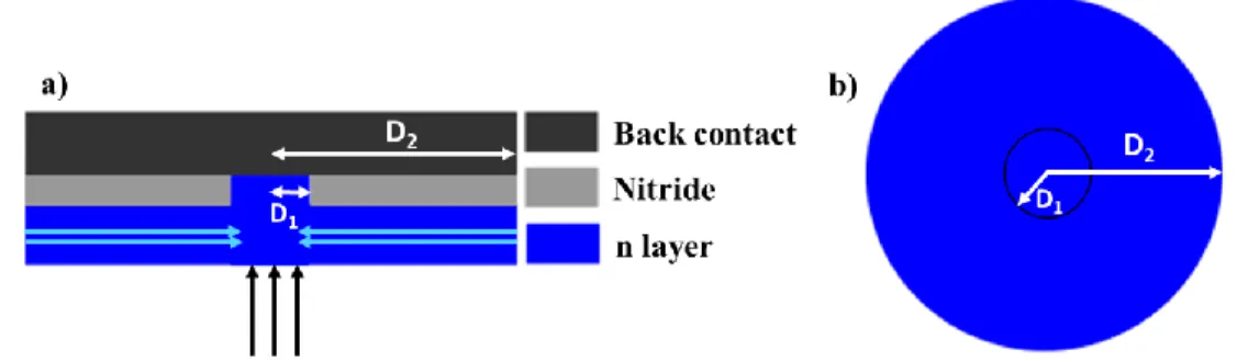
The c-Si substrate characteristics used in the theoretical calculations are a p-type wafer of 1.8 Ω.cm with a thickness of 160 µm, which is representative of typical substrates in current commercial devices. For the rear surface modelling, a 3D approach is necessary to define point-like patterns. However, due to the high computational cost of such simulations, we reduce the 3D problem to 1D by applying the equation proposed by Fischer [85], improved by Plagwitz and Brendel [86] and generalized by Saint-Cast et al. [87] that allows us to concentrate the ohmic losses in a condensed parameter Rbase and an equivalent surface
recombination velocity, Seff,rear. Additionally, 3D simulations with ATLAS/Silvaco TCAD were performed at MNT, UPC Barcelona for certain surface configurations to check the analytical results. In particular,
Rbase can be calculated using the following expression [85]:
Where r is the contact radius, p is the rear pitch, w is the wafer thickness, and ρ is the substrate resistivity. In Fig.1.14, calculated Rbase values are presented as a function of fc for contact radii of 25 and 0.5 µm
together with the results of 3D simulations that perfectly agree with the analytical model. In addition, the solid red line indicates the minimum Rbase value, corresponding to the case where all the current is flowing
vertically through the base: Rbase= ρ·w.
(1.1) p w base w e r w r p R ·tan 2 · ·1 2 · 1 2