is an open access repository that collects the work of Arts et Métiers Institute of Technology researchers and makes it freely available over the web where possible.
This is an author-deposited version published in: https://sam.ensam.eu Handle ID: .http://hdl.handle.net/10985/9263
To cite this version :
Antoine BRUYERE, Eric SEMAIL, Alain BOUSCAYROL, Jacques CHARLEY, Fabrice LOCMENT, Jean-Marc DUBUS, Jean-Claude MIPO - Modeling and Control of a 7-phase Claw-pole Starter-alternator for a Micro-hybrid Automotive Application - In: IEEE Vehicle Power and Propulsion Conference, China, 2008-09 - Vehicle Power and Propulsion Conference - 2008
Any correspondence concerning this service should be sent to the repository Administrator : archiveouverte@ensam.eu
Modeling and Control of a seven-phase
Claw-Pole Integrated Starter Alternator
for Micro-hybrid Automotive Applications
A. Bruyere *,**, E. Semail *, A. Bouscayrol *, F. Locment * J.M. Dubus **, and J.C. Mipo **
* Arts et Métiers ParisTech / L2EP, Lille, France. Email: antoine.bruyere@gmail.com ** Valeo Electrical System, Creteil, France. Email: jean-claude.mipo@valeo.com
Abstract—This paper deals with the modeling and the
control of a new high power 12V Integrated Starter Alternator (ISA). This system is used to bring micro-hybrid functions to standard Internal Combustion Engine (ICE) vehicles. The drive is composed of a seven-phase synchronous claw-pole machine with separate excitation, supplied with a seven-leg Voltage Source Inverter (VSI) designed for low voltage and high current. The system is modeled in a generalized Concordia frame and a graphical description is used to highlight energetic properties of such a complex system. A control scheme is then deduced from this graphical description. Two controls are achieved in generator mode and compared: one is using the VSI in a square-wave mode, the other in a Pulse Width Modulation (PWM) mode. Experimental results are provided.
Keywords—multiphase machine, starter-alternator, control, automotive applications, micro-hybrid vehicle
I. INTRODUCTION
ICRO-HYBRIDATION offered by starter-alternators
allows a fuel consumption reduction of conventional vehicles at very low cost [1]-[2]. Starter-alternators can be integrated in standard Internal Combustion Engine (ICE) vehicles. They are a step towards other complex and expensive hybrid technologies [3]-[5] that need a deep transformation of the mechanical powertrain. For this reason, many car manufacturers work on the standardization of this kind of technology, for all gasoline or diesel, small or big-size engines. The aims of the electrical machine used in a starter-alternator system are both: starting the ICE vehicle and recharging the lead-acid battery. The main difficulties for designers are to make a cheap drive, working under the low DC-bus voltage level (12V), and able to provide a sufficient starting torque. The Valeo StARS system (StARS for Starter Alternator Reversible System) already equips small-size gasoline engine cars with a classical 12V battery [1]. It uses the cheap common three-phase claw-pole generator installed in classical cars. However, a Voltage Source Inverter (VSI) is used to work in starter and alternator modes instead of the diode-bridge. In order to extend the range of this kind of claw-pole starter-generator vehicles, a seven-phase structure has been developed [6]. The high number of phases can improve the power flow rate between the machine and the battery and increase the torque density of
the machine [7]-[9] by using concentrated windings. Concerning the control, compared with a three-phase VSI, the seven-leg VSI adds degrees of freedom. With more freedom degrees, more constraints can be taken into account in order to improve the global performances. However, these numerous degrees of freedom and the variable excitation field require more complex control laws.
In this paper, an original control scheme is developed for the seven-phase starter-alternator. This control scheme is derived from a specific modeling. In the first section, the drive and the experimental set-up are presented. In the second section, the system is modeled in a generalized Concordia frame. Energetic Macroscopic Representation (EMR) is then used to organize the equations in a synthetic way and a control scheme is deduced from this graphical description. In the last section, two controls in generator mode are analyzed. The first one is based on a square-wave modulation of the VSI. The second control is based on a Pulse Width Modulation (PWM).
II. PRESENTATION OF THE SEVEN-PHASE DRIVE AND
MODELLING IN THE STATOR FRAME
A. Interest of the seven-phase claw-pole drive
Basically the machine is a claw pole machine, also called Lundell alternator, widely used in vehicles [1]-[2] because of its low costs of production. In order to increase the torque density necessary for the starter mode, magnets are inserted between the claws of the rotor (Figure 1. ). If it is still necessary to improve the torque without increasing the machine volume, one solution is to decrease the volume of the inactive copper end windings. In the presented starter-alternator the iron stack length of the seven-phase version can be increased by a 17% factor, increasing in the same proportion the active length of copper windings (Figure 2. and Figure 3. ). This solution is obtained by using fractional-slot concentrated windings (Figure 3. ). This kind of winding is a promising solution especially if the number of phases is not any more imposed to three since the winding factor can be high with multiphase machine [10]-[13]).
Besides, the choice of the phase number can be also linked to constraints on the VSI. For 12V high power
M
starter-alternators the current on the DC-bus is becoming very important (approximately 250A in the alternator mode, for a 3kW machine, and near than 1000A in the starter mode, for a 60 Nm machine). Consequently, for a three-leg VSI, it is not possible to use only one transistor per switch to withstand such high current levels. So, several components in parallel are required [14]. In this case, these transistors must have the same behavior all along the life of the system, relating to their control characteristics, in order to conduct and stop simultaneously. Oversizing is often necessary to ensure sufficient margin security. The increase of the number of phases can naturally alleviate this kind of problem. Moreover, on the contrary with a three phase machine, it is still possible with a seven-phase machine to work with one or two seven-phases opened [9][10][15]. The fault-tolerance, especially related to power electronics devices faults, can be increased.
Figure 1. Picture of a claw-pole rotor with permanent magnets inserted between the claws
Figure 2. Picture of three-phase machine end windings
Figure 3. Picture of seven-phase machine end windings
B. Classical modeling of the seven-phase
synchronous machine in the stator frame
In the stator frame, the seven-phase synchronous machine is modeled with the set of equations (1)-(2). In Figure 4. , a classical scheme is used to introduce the common notations: vk, as the phase “k” voltage, ik, this
phase current. The position of the rotor is θ and the excitation field current is iF. Equations (1)-(2) are
described in the stator frame. In these two equations, RS is
the phase resistance value, Φ, the magnetic flux linked by the phase k. The matrix
[
LSS(θ)]
is the stator inductances matrix, whose terms depend on the position θ in the general case. MSR is a Stator/Rotor linkage function whichis used to represent the electromotive forces (emf) creation. ⎥ ⎥ ⎥ ⎥ ⎥ ⎥ ⎥ ⎥ ⎥ ⎦ ⎤ ⎢ ⎢ ⎢ ⎢ ⎢ ⎢ ⎢ ⎢ ⎢ ⎣ ⎡ + ⎥ ⎥ ⎥ ⎥ ⎥ ⎥ ⎥ ⎥ ⎥ ⎦ ⎤ ⎢ ⎢ ⎢ ⎢ ⎢ ⎢ ⎢ ⎢ ⎢ ⎣ ⎡ = ⎥ ⎥ ⎥ ⎥ ⎥ ⎥ ⎥ ⎥ ⎥ ⎦ ⎤ ⎢ ⎢ ⎢ ⎢ ⎢ ⎢ ⎢ ⎢ ⎢ ⎣ ⎡ 7 6 5 4 3 2 1 7 6 5 4 3 2 1 7 6 5 4 3 2 1 φ φ φ φ φ φ φ dt d i i i i i i i R v v v v v v v S (1)
[
]
SR iF f f f f f f f M i i i i i i i ⎥ ⎥ ⎥ ⎥ ⎥ ⎥ ⎥ ⎥ ⎥ ⎦ ⎤ ⎢ ⎢ ⎢ ⎢ ⎢ ⎢ ⎢ ⎢ ⎢ ⎣ ⎡ − − − − − − + ⎥ ⎥ ⎥ ⎥ ⎥ ⎥ ⎥ ⎥ ⎥ ⎦ ⎤ ⎢ ⎢ ⎢ ⎢ ⎢ ⎢ ⎢ ⎢ ⎢ ⎣ ⎡ = ⎥ ⎥ ⎥ ⎥ ⎥ ⎥ ⎥ ⎥ ⎥ ⎦ ⎤ ⎢ ⎢ ⎢ ⎢ ⎢ ⎢ ⎢ ⎢ ⎢ ⎣ ⎡ ) 7 / 12 ( ) 7 / 10 ( ) 7 / 8 ( ) 7 / 6 ( ) 7 / 4 ( ) 7 / 2 ( ) ( ) ( 7 6 5 4 3 2 1 7 6 5 4 3 2 1 π θ π θ π θ π θ π θ π θ θ θ φ φ φ φ φ φ φ SS L (2)i
F1
2
3
i
1v
1θ
4
5
6
7
i
F1
2
3
i
1v
1θ
4
5
6
7
Figure 4. Schematic representation of the seven-phase synchronous machine with separate excitation
C. Experimental set-up
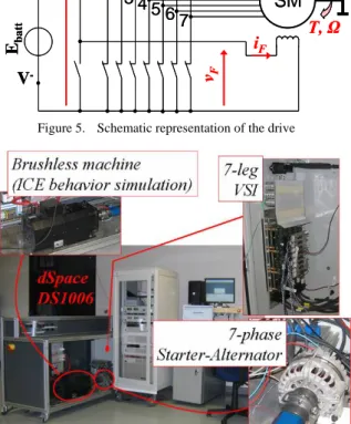
The drive is composed of a seven-phase wye-coupled synchronous machine with separate excitation. It is supplied with a seven-leg Voltage Source Inverter (Figure 5. and Figure 6. ) connected to a 12V battery. For the tests shown in this paper, the DC-bus voltage VDC is
maintained constant (VDC =12V). A variable electronic
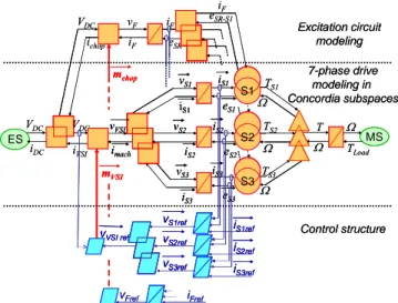
simulate the on-board electrical network energy consumptions. In Figure 6. , the experimental set-up picture shows the starter-alternator directly mechanically coupled to a brushless machine, used to simulate the ICE behavior. The whole system is managed using a dSpace DS1006 control board.
D. Example of open loop Square Wave control
in alternator mode
In this paper, the tests are provided in the alternator mode of the drive, at a constant rotation speed (N=1800rpm). For the first test, each VSI leg is controlled with a rectangular pulse commutation command synchronized with θ angle, so that each switch is imposed to be closed during half of the electrical period. This control mode is a classical “180°” Square Wave (SW) control mode. In this mode, two degrees of freedom are available for controlling the power delivered by the electrical machine: the excitation current level iexc and the
position θstart. In this example, iexc is imposed to a constant
value (iexc = 2.25 A) and θstart is imposed to be optimal for
the power transfer. In these conditions, the delivered power to the electronic load is Pdelivered = 830 W.
In order to simplify the comparisons, all experimental results are given at the fifth page (Figure 10. and Figure 11. ). The results for the open loop 180° SW control test are given in the parts “(a)” of these figures. The first main observation concerns the high maximal value of the currents, about 130A, that implies two major problems. First, these high peaks of current have to be withstood by the power electronics switches. Secondly, the lack of control on the current waveform can lead to parasitic phenomena as noisy torque ripples (Figure 12. ).
iDC SM VDC vF T, Ω 1 2 3 4 5 67 iF i1 V -V+ Rbat t Ebat t iDC SM VDC vF T, Ω 1 2 3 4 5 67 iF i1 V -V+ Rbat t Ebat t
Figure 5. Schematic representation of the drive
Figure 6. Experimental set-up picture
III. THE SEVEN-PHASE DRIVE CONTROLLED IN THE
GENERALIZED CONCORDIA FRAME
Looking at (1), seven voltages can be controlled, offering six independent freedom degrees (because of the wye-electrical-coupling). Another freedom degree is given with the excitation field current. With the 180° square wave control only two degrees of freedom are used. In this part, the generalized Concordia transformation [9], [16], [17] and the Energetic Macroscopic Representation (EMR) formalism [9], [18] are used to highlight all the degrees of freedom and to organize the model in order to easily build an efficient control structure. The aim of this second experimental test is fixed to get smoother phase currents in the same conditions than the previous test, with a same delivered power.
A. Projection of the seven-phase synchronous
machine problem in the generalized Concordia frame
Studying the special case of a seven-phase synchronous machine, the projection of the problem (1)-(2) in the generalized Concordia frames leads to the definition of three orthogonal dq-subspaces [9], [16], [17]. These subspaces are named “S1-subspace”, “S2-subspace” and “S3-subspace” (or S1, S2 and S3). Considering the assumptions of a smooth poles machine and linear magnetic materials, this mathematic transformation leads to a perfectly decoupled set of voltage equations, expressed with (3). In (3), the first equation is related to the 0-sequence i0 component, in a 0-sequence
one-dimensional subspace; it will be ignored because the electrical wye-coupling of the machine leads to an always null i0 current. Then, in S1, S2, S3, the rotating dq-frames
are defined using the eSk-q projection in Sk of the emf
vector.
Considering the simplified model (3), the currents are now slow varying values to be controlled. This new model leads to a very standard and simple scheme (Figure 7. ) for controlling each dq-currents expressed, in the 3 subspaces S1, S2 and S3. ⎪ ⎪ ⎪ ⎪ ⎪ ⎩ ⎪⎪ ⎪ ⎪ ⎪ ⎨ ⎧ + + = + = + + = + = + + = + = + + = − − − − − − − − − − − − − − − − − − − − − q S q S S q S S q S d S S d S S d S q S q S S q S S q S d S S d S S d S q S q S S q S S q S d S S d S S d S S e i R dt i d L v i R dt i d L v e i R dt i d L v i R dt i d L v e i R dt i d L v i R dt i d L v e i R dt i d L v 3 3 3 3 3 3 3 3 3 2 2 2 2 2 2 2 2 2 1 1 1 1 1 1 1 1 1 0 0 0 0 0 / ) ( / ) ( / ) ( / ) ( / ) ( / ) ( / ) ( (3)
Figure 7. Control of one single axis of a dq subspace q d, S1,2,3 q d, S1,2,3 K τ + 1 +- C(s) ++ + -ecompensation e iS 1,2,3 d,q-reference iS 1,2,3 d,q
Controller 1storder system
with e as a perturbation q d, S1,2,3 q d, S1,2,3 K τ + 1 +- C(s) ++ + -ecompensation e iS 1,2,3 d,q-reference iS 1,2,3 d,q q d, S1,2,3 q d, S1,2,3 K τ + 1 S1,2,3d,q q d, S1,2,3 K τ + 1 + -+- C(s)C(s) +++++ ++- -ecompensation e iS 1,2,3 d,q-reference iS 1,2,3 d,q
Controller 1storder system
B. Energetic Macroscopic Representation and deduced control structure
Six independent equations are thus obtained. These equations are considered by pairs, in Concordia subspaces, along d- and q-axes. For the EMR (Figure 8. ), this two-dimensional subspace notion is used. Using EMR [18], the orange elements depict the energetic system and the blue elements describe the control structure (cf. appendix A1). Two main properties of EMR are:
- The respect of the natural causality;
- Each action value goes in pair with its reaction value (right and left oriented arrows) and the product of both action and reaction is the power.
In the EMR of the system, (Figure 8. ), the excitation current (symbolized by the upper element with accumulation of energy; cf. A1) interacts with each S1, S2 and S3 subspaces and participates to the creation of the electromotive forces and the torques TS1, TS2, TS3. The total
torque T is the sum of these three torques (overlapped triangle).
Then, the control structure is obtained by inversion of the tuning chain with the respect of the natural causality. This, in order to avoid time-consuming algebraic loops. The control of each current is achieved independently from the others. Figure 9. gives the details of the electrical model (3) represented with EMR. The control blocks of the dq-currents are also detailed. In these control blocks, we can notice that the electromotive force eris compensated. The controllers Cd(s) and Cq(s) are
Proportional Integral (PI) controllers, which transfer function form is Kp+Ki/s, where Kp is the proportional gain
and Ki the integral gain of the controller. After
identification of the inductive and resistive parameters of the drive [19], these PI controllers are tuned for each d- and q-axes, in S1-, S2- and S3-subspaces, using the KLV method [20].
C. Control for smoother stator currents
For this second test, the rotation speed is the same as the first test speed; N = 1800 rpm. As eS2-q and eS3-q are
weak in comparison with eS1-q, it is chosen to control the
energy flow only through the S1 subspace. Thus, the S2 and S3 d- and q- currents are controlled to be null. In order to minimize the copper losses for a given torque (see (3)), iS1-d is also chosen to be null. Then, iF is tuned to the
minimal value in order to get the same delivered power than the previous test. Pdelivered = 830 W for iF = 3 A.
The objective of smoother current is established. The maximal stator currents value is 55A, in comparison with 130A for the SW mode. This decrease of more than 50% concerning the maximal amplitude of the currents can be compared with the increase of the excitation by 33% (from 2.25A to 3A). With this PWM mode, in the generalized Concordia frame, currents in S1, S2, S3 subspaces are controlled.
eSR-S1 eSR iF VDC Ω TLoad T Ω MS vS1 eS1 iS1 iS2 iS3 vS2 vS3 eS3 eS2 TS1 TS2 TS3 Ω iS1 iS2 iS3 iVSI Ω vVSI imach mVSI ichop ES VDC iDC vF iF mchop iF vS1ref i S1ref vVSI ref iS2ref iS3ref vS2ref vS3ref vFref iFref Excitation circuit modeling Control structure 7-phase drive modeling in Concordia subspaces S1 Ω S2 S3 VDC eSR-S1 eSR iF VDC Ω TLoad T Ω MSMS vS1 vS1 eS1 eS1 iS1 iS1 iS2 iS2 iS3 iS3 vS2 vS2 vS3 vS3 eS3 eS3 eS2 eS2 TS1 TS2 TS3 Ω iS1 iS1 iS2 iS2 iS3 iS3 iVSI Ω vVSI vVSI imach imach mVSI mVSI ichop ES VDC iDC vF iF mchop mchop iF vS1ref vS1ref i S1ref iS1ref vVSI ref vVSI ref iS2ref iS2ref iS3ref iS3ref vS2ref vS2ref vS3ref vS3ref vFref iFref Excitation circuit modeling Control structure 7-phase drive modeling in Concordia subspaces S1 Ω S2 S3 VDC
Figure 8. EMR modeling and control of the seven-phase synchronous machine with separate excitation in the generalized Concordia frame
iS 1,2,3 d ref + - Cd(s) + + + -ecompensation d ed iS 1,2,3 d +- Cq(s) ++ + -ecompensation q eq iS 1,2,3 q ref iS 1,2,3 q iS 1,2,3 iS 1,2,3 reference vS 1,2,3 d S1,2,3 d S1,2,3 τ K + 1 q S1,2,3 q S1,2,3 τ K + 1
Two 1storder system
(d- and q-axes) with e as a perturbation d- and q-currents controllers Cd,q(s),
with compensation of the perturbation e iS1,2,3ref eS1,2,3 vS1,2,3 iS1,2,3 iS1,2,3 iS 1,2,3 d ref + -+ - CCdd(s)(s) + + +++ ++- -ecompensation d ed iS 1,2,3 d + -+- CCqq(s)(s) +++++ + -+ -ecompensation q eq iS 1,2,3 q ref iS 1,2,3 q iS 1,2,3 iS 1,2,3 iS 1,2,3 reference iS 1,2,3 reference vS 1,2,3 vS 1,2,3 d S1,2,3 d S1,2,3 τ K + 1 q S1,2,3 q S1,2,3 τ K + 1
Two 1storder system
(d- and q-axes) with e as a perturbation d- and q-currents controllers Cd,q(s),
with compensation of the perturbation e iS1,2,3ref iS1,2,3ref eS1,2,3 eS1,2,3 vS1,2,3 vS1,2,3 iiS1,2,3S1,2,3 iS1,2,3 iS1,2,3
Figure 9. Model and control structure of the currents in the dq-subspaces
IV. COMPARISON BETWEEN TWO EXPERIMENTAL TESTS
FOR BOTH SW AND PWM CONTROLS
A comparison of the two experimental tests in the generator mode of the machine is given with Figure 10. , Figure 11. and Figure 12. . For each figure, the “(a)” part concerns the open loop Square Wave (SW) control mode, and the “(b)” part concerns the closed loop Pulse Width Modulation (PWM) control mode established in the generalized Concordia frame.
Concerning the currents waveform in the stator frame (Figure 10. ), the difference between the two modes is obvious. Without controlling the currents (SW mode), the maximal phase currents value is about 130A and about 55A when the currents are controlled in the generalized Concordia frame. The delivered electrical power is the same for both tests (in the generator mode of the machine, for these experimental tests, Pdelivered = 830 W).
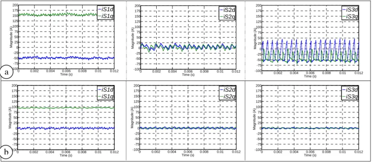
Then, regarding the currents in the control-S1-, S2- and S3-subspaces (Figure 11. ), it can be also noticed that: - In the S1-subspace, the current along the d-axis
(iS1-d) is not null with the SW mode, which indicates
that the copper losses are not minimized;
- The pulsating currents observed in S2- and S3-subspaces, with the SW mode, are at the origin of pulsating torques (Figure 8. ).
Concerning the torque, Figure 12. shows the difference between the measured torques for both control modes: a better control of the currents in the generalized Concordia frame allows the reduction of the torque ripples, from about 12Nm with the SW control mode, to about 6Nm
with the PWM control established in the generalized Concordia frame. These torque pulsations can be at the origin of noise [21], which is particularly embarrassing with this kind of automotive application at low speeds.
0 0.002 0.004 0.006 0.008 0.01 0.012 -150 -125 -100 -75 -50 -25 0 25 50 75 100 125 150 Time (s) Magn it ude ( A ) i1 i2 i3 i4 i5 i6 i7 0 0.002 0.004 0.006 0.008 0.01 0.012 -150 -125 -100 -75 -50 -25 0 25 50 75 100 125 150 Time (s) Magn it ude ( A ) i1 i2 i3 i4 i5 i6 i7
Figure 10. Currents waveforms in the stator frame:
for the open loop 180° square wave control (a): N = 1800 rpm, iF = 2.25 A, Pdelivered = 830 W,
and for the PWM control in the generalized Concordia frame (b), N = 1800 rpm, iF = 3.00 A, Pdelivered = 830 W
0 0.002 0.004 0.006 0.008 0.01 0.012 -100 -75 -50 -25 0 25 50 75 100 125 150 175 200 Time (s) Magni tude ( A ) iS1d iS1q 0 0.002 0.004 0.006 0.008 0.01 0.012 -100 -75 -50 -25 0 25 50 75 100 125 150 175 200 Time (s) Magni tude ( A ) iS2d iS2q 0 0.002 0.004 0.006 0.008 0.01 0.012 -100 -75 -50 -25 0 25 50 75 100 125 150 175 200 Time (s) Magn it ude (A ) iS3d iS3q 0 0.002 0.004 0.006 0.008 0.01 0.012 -100 -75 -50 -25 0 25 50 75 100 125 150 175 200 Time (s) M agn it ud e (A ) iS1d iS1q 0 0.002 0.004 0.006 0.008 0.01 0.012 -100 -75 -50 -25 0 25 50 75 100 125 150 175 200 Time (s) M agn it ud e (A ) iS2d iS2q 0 0.002 0.004 0.006 0.008 0.01 0.012 -100 -75 -50 -25 0 25 50 75 100 125 150 175 200 Time (s) Ma gn it ud e ( A ) iS3d iS3q
Figure 11. Projection of the stator currents in the S1, S2 and S3 subspaces,
for the open loop 180° square wave control (a) and for the PWM control in the generalized Concordia frame (b) (the delivered electrical power is the same for both tests, in the generator mode of the machine, Pdelivered = 830 W)
0 0.002 0.004 0.006 0.008 0.01 0.012 0 2 4 6 8 10 12 14 16 18 20 Time (s) Tor q ue ( N m ) 0 0.002 0.004 0.006 0.008 0.01 0.012 0 2 4 6 8 10 12 14 16 18 20 Time (s) Tor que ( N m )
Figure 12. Torque measurement for the open loop 180° square wave control (a) and for the PWM control in the generalized Concordia frame (b) (the delivered electrical power is the same for both tests, in the generator mode of the machine, Pdelivered = 830 W)
a
b
a
b
V. CONCLUSION
A new starter-alternator with seven phases has been developed. It is a solution to extend this kind of micro-hybrid technology to powerful vehicles. The drive keeps the cheap claw-pole machine standard structure and a 12V battery. The present square-wave control of the VSI allows satisfying the objective on power. Nevertheless, harmonics of currents are not controlled. In this paper, a modeling of the drive has been developed in order to improve the quality of the phase currents waveform. A generalized Concordia transformation is used to project the model of the phase drive, from a seven-dimensional space to three independent 2-seven-dimensional subspaces. Moreover, the use of EMR formalism gives a global synthetic graphical view of the energetic flows in the generalized Concordia frame. The structure of control is easily deduced by a systematic inversion in respect with causality. The interest of this control is shown by the comparison of two kinds of control in terms of quality of currents waveform. Smoother currents with the control established in the generalized Concordia frame lead to a smoother measured torque.
APPENDIX
A1: Elements of EMR and of control:
Source of energy Electrical coupling device (energy distribution) Electromechani cal converter with electrical coupling Element with energy accumulation Electrical converter (without energy accumulation) Mechanical coupling device (energy distribution) Control block with controller Control block without controller Action and reaction variables.
Product of both is the power.
REFERENCES
[1] D. Richard, Y. Dubel, “Valeo StARS Technology: A competitive Solution for Hybridization”, Power Conversion Conference,
PCC’07 Nagoya, Japan, pp. 1601605, April 2007, ISBN: 1-4244-0844-X.
[2] Boldea, “Starter/Alternator Systems for HEV and Their Control: A Review”, KIEE International Transactions on Electrical
Machinery and Energy Conversion Systems, Vol. 4-B No. 4, pp. 157~169, 2004.
[3] C.C. Chan, "The state of the art of electric, hybrid, and fuel cell vehicles". Proc. of the IEEE, Vol. 95, No.4, pp. 704 - 718, April 2007.
[4] V. Wouk, “Hybrids: then and now”, IEEE Spectrum, Vol. 2, Issue 7, pp. 16-21, ISSN : 0018-9235, July 1995.
[5] M. Ehsani, Y. Gao, S. E. Gay, A. Emadi, “Modern Electric, Hybrid Electric, and Fuel Cell Vehicles”, CRC PRESS, 2005, ISBN 0-8493-3154-4.
[6] J. M. Dubus, A. De Vries, D. Even and J. C. Mipo: "Polyphase stator of a rotating electrical machine with claw-pole rotor and alternator or alternator starter comprising same", French Patent WO 2007/031679 A2, March 2007.
[7] B. Zhang, H. Bai, S. D. Pekarek, W. Eversman, R. Krefta, G. Holbrook, D. Buening, “Comparison of 3-, 5-, and 6-Phase Machines For Automotive Charging Applications” International
Electric Machines and Drives Conference, EMDC’03 USA, 1-4, vol.3, pp.:1357 – 1362, June 2003.
[8] F. Locment, A. Bruyere, E. Semail, X. Kestelyn, A. Bouscayrol and J. M. Dubus, “Comparison of 3-, 5- and 7-leg Voltage Source Inverters for low voltage applications”, IEEE International Electric Machines and Drives Conference, IEMDC 2007, Antalya, Turkey, pp. 1234-1239, May 2007, ISBN: 1-4244-0743-5.
[9] F. Locment, E. Semail, X. Kestelyn, A. Bouscayrol, “Control of a seven-phase axial flux machine designed for fault operation“,
IEEE International Conference On Industrial Applications of Electronics, IECON’06, Paris, France, November 7 – 10, 2006, pp. 1101 – 1107.
[10] M. Abolhassani, “A novel multiphase fault tolerant high torque density permanent magnet motor drive for traction application",
Proc. of IEEE-IEMDC'05, San Antonio, USA, May 2005, pp. 728-734.
[11] F. Scuiller, E. Semail, J.F Charpentier, « Multi-criteria based design approach of multiphase permanent magnet low speed synchronous machines”, IET Trans. Electric Power Applications, in press.
[12] J. Cros, P. Viarouge, “Synthesis of high performance PM motors with concentrated windings”, IEEE Transaction on Energy Conversion, Volume 17, Issue 2, Jun 2002 Page(s): 248 – 253. [13] J. Figueroa, J. Cros, P. Viarouge, “Polyphase PM brushless DC
motor for high reliability application”, Proc. of EPE 2003, Toulouse (France), Sept.2003, CD-ROM.
[14] Jingbo Liu, Jiangang Hu and Longya Xu “Design and Control of a Kilo-Amp DC/AC Inverter for Integrated Starter-Generator (ISG) Applications”, IEEE industry applications conference, October 2004, Seattle, USA.
[15] M. Abolhassani, “A Novel Multiphase Fault Tolerant Permanent Magnet Motor Drive for Fuel cell Powered Vehicles”, IEEE VPPC 2007, Sept 2007, Texas, USA.
[16] J. Figueroa, J. Cros, P. Viarouge, “Generalized transformations for polyphase phase-Modulation motors”, IEEE Transaction on Energy Conversion, Vol. 21, Issue 2, pp. 332-341, June 2006, ISSN: 0885-8969.
[17] E. Levi, R. Bojoi, F. Profumo, H. A. Toliyat, S. Williamson, “Multiphase induction motor drives- A technology status review”,
Electric Power Applications, IET, Vol. 1, issue 4, pp. 489-516, July 2007.
[18] A. Leclercq, P. Sicard, A. Bouscayrol, B. Lemaire-Semail, "Control of a triple drive paper system based on the Energetic Macroscopic Representation", IEEE-ISIE’04, proceeding pp. 889-893, Ajaccio, France, May 2004.
[19] A. Bruyere, E. Semail, F. Locment, A. Bouscayrol, J-M Dubus, J-C. Mipo, “Identification of sensitive R-L parameters of a multiphase drive by a vector control”, IEEE Power Electronics
Specialists Conference, PESC08, Rhodes, Greece, June 2008. [20] I.D. Landau, A. Voda, “An analytical method for the
auto-calibration of PID controllers”, Proceedings of the 31st IEEE Conference on Decision and Control, vol. 4, pp. 3237-3242, Dec. 1992.
[21] J. F. Gieras, C. Wang, J. Cho Lai, “Noise of Polyphase Electric Motors”, Taylor & Francis book, CRC PRESS, 2006, ISBN 0-8247-2381-3