Science Arts & Métiers (SAM)
is an open access repository that collects the work of Arts et Métiers Institute of Technology researchers and makes it freely available over the web where possible.
This is an author-deposited version published in: https://sam.ensam.eu
Handle ID: .http://hdl.handle.net/10985/7716
To cite this version :
Jawhar ELGUEDER, Florent COCHENNEC, Lionel ROUCOULES, Emmanuelle ROUHAUD -Product-process interface for manufacturing data management as a support for DFM and virtual manufacturing - In: The 7th International Meeting - The International Conference on Integrated, Virtual and Interactive Engineering for fostering Industrial Innovation, China, 200810
-Proceedings of IDMME - Virtual concept 2008 - 2008
Any correspondence concerning this service should be sent to the repository
Product-process interface for manufacturing data management
as a support for DFM and virtual manufacturing
Jawhar Elgueder 1, Florent Cochennec 1, Lionel Roucoules 1, Emmanuelle Rouhaud 1
(1): University of technology of Troyes, Charles Delaunay Institute – FRE 2848, Laboratory of
Mechanical Systems and Concurrent Engineering. 12, rue Marie Curie BP2060 10010 TROYES Cedex FRANCE.
Phone: +33 3 35 71 80 17/Fax: +33 3 25 71 56 75 E-mail : [email protected]
Abstract: In order to tackle a continuous improvement of
virtual engineering, product modelling has to integrate always more knowledge that refer to every decision taken during the product development process. Those decisions have to be related to the assessment of the whole product lifecycle. This paper particularly addresses the domain of product’s industrialisation that aims at selecting the manufacturing processes. This selection must currently be done as soon as possible and has to be strongly linked with product definition
and CAD1 modelling.
This paper presents first some new results concerning a product-process interface to integrate manufacturing information in the product model and how it leads the definition of the CAD model. Secondly this interface, that also manages specific information coming from the manufacturing process (tolerances, stresses gradient…), is used to improve the whole manufacturing process plan simulation. This process plan has, indeed, to track every material transformation issued from each manufacturing operation.
Key words: product-process interface, DFM, virtual
engineering, manufacturing process selection, manufacturing simulation.
1- Introduction
For almost 30 years CAD systems have been developed and improved to currently reach very powerful features to support product’s forms modelling. Nevertheless they are actually presented and used as one of the central systems that make the design process a geometric centric approach. This approach has shown its great interest in industry to tackle the problem of
digitizing hand-done drawing or to improve the CAD-CAM2
links and to enhance the process plan activity. Nowadays, the CAD model also finds an interest to improve the digital mock-up used during a decision making process for instance.
1
Computer Aided Design
2
Computer Aided Manufacturing
However current CAD systems are not able to manage all the information related to the product definition. This information as mentioned in [KK1] has to be related to the whole lifecycle (from requirement specifications to dismantling information). The product, and its CAD model, is then defined, as far as possible, taken into account “X”
constraints as assumed in a DFX3 approach. One of the
domains that have to be integrated in design is manufacturing (i.e. DFM). That means that manufacturing activities have to be assessed concurrently to the product development and the CAD modelling activity.
Once the CAD done, manufacturing processes can be detailed. As far manufacturing simulation is concerned, CAD model is seen as input and software tools have to simulate the behaviour of the materials flow during each
manufacturing operation (ex : forging, casting,
machining….).
The main issue of that design approach remains in the fact that:
- The CAD model is almost never defined taking into
account manufacturing information.
- The manufacturing simulations do not take into
account the history of the whole process planning. The input CAD is very often seen as virgin of any previous manufacturing operation.
This paper gives some results to manage the whole manufacturing process plan information and to integrate those data (i.e. knowledge synthesis approach) in the CAD model that is, then, constructed with respect to a more adequate DFM approach.
3
Design For X: design approach able to take into account activity information (e.g. manufacturing, assembly…) during the product development.
The second part introduces the design approach and the main concepts used to breakdown the product and its CAD model. It also gives the product-process interface concepts used to tackle the information synthesis.
The third part gives the first ideas and results to manage the manufacturing information of the global process in order to use it during the whole manufacturing simulation process.
Finally the conclusion and the perspectives for further work are enounced.
2- Objectives, context and concepts of the DFM approach
The fundaments of authors’ DFM approach are the integration
of manufacturing information4 constraints and data at the
earliest stage of design. The developed model of integration (i.e. product-process interface model) is based on the research work done by Roucoules and Skander [RS1]. They showed that taking manufacturing information into account as soon as possible in the design process is of great interest for manufacturing process selection. That indeed supports the emergence of product geometry [RL1] and goes towards a limited number of iterations between design and manufacturing decisions; the term of “right the first time” is used for such approaches versus the approaches of “do until right”.
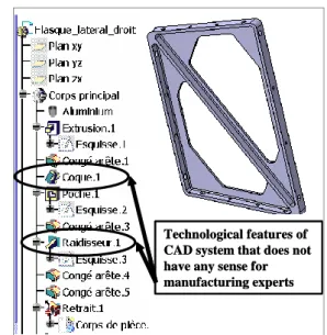
Considering that the manufacturing domain is extended to other product lifecycle phases (e.g. assembly, recycling, dismantling, etc.), the assumption is that the design process should then be centred on multiple-views product modelling and expert analyses instead of being CAD centric. One of the main issues of that CAD centric approach remains in the unique product breakdown that does not reflect the design intends of every expert designers involved in the design group. Figure 1 shows the features breakdown used to obtain the CAD model. Obviously, this breakdown does not represent what should or could be the real manufacturing process plan. It does not have any sense for the engineers in charge of the manufacturing activities.
4
Information is used in this work as both “new data” that complete product or process definition or “constraints” that is used to reduce the range of value of an existing data. Some details can be found in [RL1].
Technological features of CAD system that does not have any sense for manufacturing experts Technological features of CAD system that does not have any sense for manufacturing experts
Figure 1: Incoherency between CAD model breakdown and manufacturing breakdown.
2.1- Design context: CE, DFM and product modelling
Integrated design aims at linking all mechanical expertises taking part in the design of a new product from functional specifications to the product’s industrialisation and dismantling. Since this design concept appeared (more or less since two decades), many research investigations have been done to propose design methods, information management methods and models supporting the collaborative activities [S2] [AH1]. It is not the issue of this paper to detail all those works.
The general context of authors’ research work lies on the multiple views product breakdown concepts proposed in [T2]. As presented in [RT1], the first design step consists in the definition of functional surfaces to achieve design requirements. These functional surfaces can emerge from specific “Function-Structure” analysis that describes every product specifications as energetic flows in the product structure. One example based on FBS [G1] and bond-graph concepts [T1] is given in [KR1]. The second steps aims at adding (i.e. integrating) lifecycle information to this first product description. This approach is often called “design by least commitment”.
Skander et al. [S1] treat the activity of “manufacturing processes selection” (i.e. manufacturing expertise on figure 2) and then proposed to apply the Design For Manufacturing approach as soon as the first functional surface is defined. They thus propose a specific product model based on an adaptation of the skin and skeleton concepts [MW1, TB1] to allow the “X” constraints integration (see figure 2), and specifically the manufacturing constraints integration [R1 and S1].
This specific product model can be seen as an “interface model” used to specify, vulgarize the product information issued from different activities (i.e. expertises) (e.g. “technological components selection” or “manufacturing processes selection”). These interface models (e.g.
product-process interface) are translated into a collaborative multiple views definition of the product.
The central “product modelling” concepts, and specifically the “relation” concept, are then used to link and/or propagate data from different expertises.
Product Model Interface model Manufacturing skin Manufacturing skeleton Technological expertise Interface model Technological skin Technological skeleton Interface model X skin X skeleton X-expertise Manufacturing expertise
Figure 2: Product modelling for “X” constraints integration.
2.2- Objectives of the DFM approach
Once the first functional surfaces are specified, the design actor in charge of the industrialisation should wonder about which manufacturing processes would be eligible for generating these surfaces. Many industrial and research studies have been done to characterise product-process relationships (e.g. [BD1]). Skander et al. proposed to translate these product-process relationships in specific skin and skeleton attributes in order to analyse the correlation between product specifications and the process-resulting product characteristics. Then, the translation of the energetic flows definition in specific skin and skeleton attributes will lead to the creation of a technological interface model (see figure 2) and the translation of the product-process relationships in a same way will lead to the creation of
manufacturing interface model corresponding to the product
alternatives resulting from the analysis of all available manufacturing processes capabilities. Checking the consistency of the data contained in these two interface models will then imply the acceptance of some product-process alternatives and the reject of some others. The acceptance criteria are based on the fact that the data obtained during the product-process constraints identification must be sufficiently pertinent to define the process capabilities.
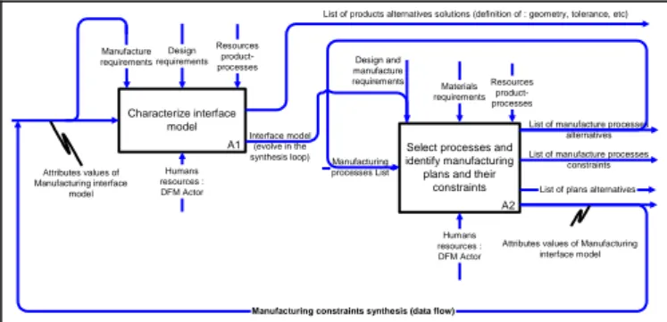
The DFM activity is detailed in figure 3. The first task (A1) aims at analysing the requirements specification using energetic flows and specific technological interface model as presented on figure 2. Once this task achieved, designers have to find product-process alternatives in which the manufacturing constraints are integrated (A2). The DFM output is then a list of products with respect to available manufacturing plans. The selection of the final product-process alternatives is not treated in the presented approach. Indeed, such a choice is led by economic criterions and depends on many external factors as the factory production capabilities, the lead-time of the production… The authors are nevertheless convinced that the proposition of product-process alternatives in which manufacturing constraints have been integrated brings solid arguments to the process selection activity.
A1 Characterize interface model Design requirements Manufacture requirements A2 Select processes and identify manufacturing plans and their
constraints
Materials requirements
List of manufacture processes alternatives Manufacturing processes List Humans resources : DFM Actor Humans resources : DFM Actor
List of plans alternatives List of manufacture processes
constraints Resources product-processes Resources product-processes Interface model (evolve in the synthesis loop)
Manufacturing constraints synthesis (data flow)
List of products alternatives solutions (definition of : geometry, tolerance, etc)
Design and manufacture requirements Attributes values of Manufacturing interface model
Attributes values of Manufacturing interface model
Figure 3: The DFM activity schematisation [RS1].
2.3- Product-process interface modelling
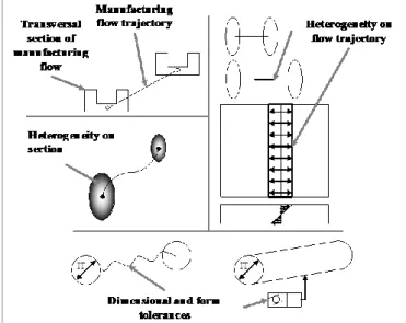
As mentioned above the integration of manufacturing information is based on a specific product-process interface. That model comes from the assumption that every manufacturing operation is based on a material flow. Those flows (cf. Figure 4) are then defined with:
- Sections defining the initial and final surfaces
through which the material is going (i.e. transversal surfaces).
- A trajectory on which the material is formed.
- An envelope section which is generated.
Flow trajectory Transversal initial surface Envelope surface Flow trajectory Transversal initial surface Envelope surface
Figure 4: Material flow definition for product-process interface.
Based on that flow (called manufacturing skeleton) the material can be added (ex: injection), removed (ex: machining) or deformed (ex: forging) to obtain the final part surfaces (called manufacturing skin). Those surfaces are in the added and removed processes categories equal to the envelope surface.
Beyond very good results presented in [SR1] that concerns the current results of that approach for nominal aspects, figure 8 gives the novelties of that paper. The new results concern the capabilities of that product-process interface:
- To manage product tolerances coming from
manufacturing operations. Each level of tolerancing features (dimensional tolerances, form tolerances and roughness) is concerned. Figure 8 shows how those features are integrated in the product-process
interface (i.e. manufacturing skeleton)
characteristics.
- To manage material heterogeneity coming from
manufacturing operations. It is also obvious that material flows (cf. above assumption) generate some gradients inside the manufactured product. Those gradients (called in the following
“heterogeneities”) can, for instance, come from (cf. Figure 8):
o Thermal phenomena in the skeleton’s
sections that come from a cooling phase which is not always homogeneous during casting operations.
o Mechanical stresses gradient on the
skeleton’s trajectory coming from high deformation in forging operations.
Another example of that heterogeneity (i.e. residual stresses) is given on the following section. It is based on peen forming process. More details can nevertheless be found in [CR1].
2.4- Application of product-process interface to the peen-forming process
The peen-forming process is a cold-work forming process mainly used in the aeronautical and aerospace industry to form large metallic panels (cf. Figure 5). The concept is to project balls on the part in order create some local plastic deformation. The global elastic equilibrium then generates geometrical deformation.
Figure 5: Illustration of the peen forming process.
It presents many advantages for this kind of application: none spring-back problems are encountered; the parts can be formed at ambient temperature, the process induces little metallurgical modifications and none dilatational dispersions; the residual stresses states are partially mastered; a good reproducibility can be achieved [RK1]. Being used for more than fifty years, this process is still under industrial and research development. Many analytical and numerical models are proposed in the literature for predicting the geometrical distortions induced [G2], [GA1], [HV1] and [HO1]. These models are based on the numerical introduction of equivalent plastic strains as a boundary condition of a finite element problem, which implies that the plastic strain fields induced by the treatment must be known. Some models have been proposed to predict the residual stress fields induced by known peening parameters [RD1] but these models are still to be developed in order to complete the state of knowledge of the process. These studies are indeed depending on the treated materials and on the peening parameters retained for the treatment. The actual state of knowledge makes thus difficult to plan the forming phases and trials and tests are still a needed way to achieve a specific
geometry. This section treats the use of mechanical analysis to identify the product-process interface (i.e. material flow as presented in 2.3) as presented in [S1] in order to integrate, as soon as possible, peen forming information in the product definition following the general design approach presented in 2.2.
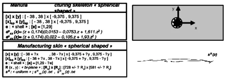
The Peen Forming process specificity lies on the fact that the material flow induces an elastic response of the sheet blank which generates the global distortion. Indeed, contrary to classical forming processes as stamping for example, only gentle curved shapes can be obtained due to the fact that the forming mechanism is based on elastic deformations and not chiefly on plastic ones. Then, the forming origin is the incompatible plastic strain field induced by the shot impacts while the forming mechanism involved lies on the elastic strains resulting from the material compatibility condition. The authors decided as a first assumption to model the material flow taking only into account the plastic strains induced by the treatment, this data being the starting point of the study of the distortions induced. Three basic curving attributes must be defined to cover the process capabilities: cylindrical, spherical and saddle shaped, the combination of these three attributes for the description of a large sheet metal being of course thinkable. Let us concentrate on the spherical form attribute, which is the simplest one. An illustration of a manufacturing skeleton and its corresponding manufacturing skin is given in figure 6.
[x] x [y] : [ - 38 , 38 ] x [ -9,375 , 9,375 ] [x]spx [y]sp: [ - 38 , 38 ] x [ -9,375 , 9,375 ] e : « shell » ; [e] = [1,29] ep xx(z)= (z + 0,174)(0,0153 – 0,0753.z + 1,611.z2 ) ep yy(z)= (z + 0,174).(0,022 – 0,105.z + 1,93.z2 )
Manufa cturing skeleton « spherical shaped » x y [x] x [y] : [ - 38 + ? x , 38 - ? x ] x [ -9,375 + ? y , 9,375 - ? y ] [x]RSx [y]RS: [ - 38 + ? x , 38 - ? x ] x [ -9,375 + ? y , 9,375 - ? y ] e : « shell » ; [e] = [1,29 - ? e] R (x , y) : « bi-plane » ; [Rx] x [Ry] : [728 +/- ? Rx] x [581 +/- ? Ry] sR : « uniform » ; sR xx (z) .txt , sR yy(z) .txt
Manufacturing skin « spherical shaped »
sR (z) [x] x [y] : [ - 38 , 38 ] x [ -9,375 , 9,375 ] [x]spx [y]sp: [ - 38 , 38 ] x [ -9,375 , 9,375 ] e : « shell » ; [e] = [1,29] ep xx(z)= (z + 0,174)(0,0153 – 0,0753.z + 1,611.z2 ) ep yy(z)= (z + 0,174).(0,022 – 0,105.z + 1,93.z2 )
Manufa cturing skeleton « spherical shaped » x y [x] x [y] : [ - 38 , 38 ] x [ -9,375 , 9,375 ] [x]spx [y]sp: [ - 38 , 38 ] x [ -9,375 , 9,375 ] e : « shell » ; [e] = [1,29] ep xx(z)= (z + 0,174)(0,0153 – 0,0753.z + 1,611.z2 ) ep yy(z)= (z + 0,174).(0,022 – 0,105.z + 1,93.z2 )
Manufa cturing skeleton « spherical shaped » x y [x] x [y] : [ - 38 + ? x , 38 - ? x ] x [ -9,375 + ? y , 9,375 - ? y ] [x]RSx [y]RS: [ - 38 + ? x , 38 - ? x ] x [ -9,375 + ? y , 9,375 - ? y ] e : « shell » ; [e] = [1,29 - ? e] R (x , y) : « bi-plane » ; [Rx] x [Ry] : [728 +/- ? Rx] x [581 +/- ? Ry] sR : « uniform » ; sR xx (z) .txt , sR yy(z) .txt
Manufacturing skin « spherical shaped »
sR (z) [x] x [y] : [ - 38 + ? x , 38 - ? x ] x [ -9,375 + ? y , 9,375 - ? y ] [x]RSx [y]RS: [ - 38 + ? x , 38 - ? x ] x [ -9,375 + ? y , 9,375 - ? y ] e : « shell » ; [e] = [1,29 - ? e] R (x , y) : « bi-plane » ; [Rx] x [Ry] : [728 +/- ? Rx] x [581 +/- ? Ry] sR : « uniform » ; sR xx (z) .txt , sR yy(z) .txt
Manufacturing skin « spherical shaped »
sR (z)
Figure 6: Illustration of manufacturing skeleton concepts in a peen formed product case.
2.5- Illustration of the product-process interface in the DFM approach
Keeping in mind the CAD model presented on figure 1 and taken into account the previously presented product-process interface, the manufacturing product breakdown would be the following (cf. Figure 7):
- An extrusion operation as primary process.
Tolerances are integrated in the section of the extrusion skeleton. (Step 1)
- A profiling machining operation as secondary
process. (Step 2)
- Four machining operations as secondary processes.
Step 1 Step 2 Step 3 Step 1 Step 2 Step 3
Figure 7: Illustration of the proposed DFM approach.
Figure 8: Example of product information issued from manufacturing process and managed by the product-process
interface.
The CAD model is then created according to manufacturing information (i.e. manufacturing skeleton) that leads the CAD breakdown and all the information related to product tolerances (as presented on Figure 8).
3- Managing manufacturing information for manufacturing process simulation
So far we have presented how product-process interface is used in a DFM approach. The second goal is to take into account this new information of material heterogeneity (cf. figure 8) to better simulate each manufacturing operation. Every simulation can then, indeed, integrate an initial state with respect to the history of previous operations of the process plan. It is then compulsory to model every gradient of information (ex: stresses coming from forging, casting…) coming from this history.
3.1- Manufacturing Data management
Figure 9 gives an overview of a KBE5 application developed
to manage the global process plan with respect to the previously presented product-process interface.
That application proposes via its Graphic User Interface to manage both process and product information. The main functions are:
- To select manufacturing process that could respect
the requirements specification coming from the first step of the design approach (cf. 2.).
- To define every manufacturing operation
parameters. This is, so far, done manually by the user according to his experience and the final part he wants to create.
- To define, via a database, product features based on
manufacturing skeleton. That includes:
o The emergence of the product CAD model
integrating all the manufacturing
variability.
o The tolerances on the product coming from
manufacturing capability.
o The product’s material behaviour (ex:
stresses gradient) coming from material flows.
The final structure breakdown therefore gives every product alternatives according to manufacturing process plan alternatives (cf. breakdown tree on Figure 9) chosen by the user. It is important to note that each manufacturing alternative provides a CAD alternative and different material heterogeneity. The evolution of the CAD after each manufacturing operation with respect to that heterogeneity and to the simulation is then also different for each alternative. That why it is nowadays important to manage all the manufacturing information.
The data model of the KBE application is currently
implemented using OCAF6 package encapsulated in MFC7
objects and Open CASCADE 3D viewer.
5
KBE: Knowledge Based Engineering. Software developed in order to link CAD systems and Knowledge database
6
Open CASCADE Application Framework
7
How to define a CAD model taking into account manufacturing information Product-process database DLL skeleton
(TDF_Label) (Produit) : Produit_1
• (TDF_Label) (Procede) : Procede_1_1 • (Std_XXXX) (Type) : Usinage
• (TDF_Label) (Groupe_Parametre) : Parametres_procede_1_1 • Std_Float (vitesse_de_coupe) : 200
• Std_int (nbre_passe) : 3 • (TDF_Label) (Squelette) : Squelette_1_1
• (TDF_Label) (Trajectoire) : traj_1_1
• (Std_XXXX) (Type) : Rectiligne
• Gp_Pnt (point_depart) : 0,0,0
• Gp_Pnt (point_final) : 100,0,0
• Std_Int (tolerance) : 8
• (TDF_Label) (Section) : section_1_1
• (Std_XXXX) (Type) : circulaire
• Gp_Pnt (centre) : 0,0,0
• Gp_Pnt (rayon) : 10
• Std_Int (tolerance) : 6
• (Std_Shape) : Shape_Squelette_1_1 • (TDF_Label) (Peau) : Peau_1_1
• (Std_Shape) : Shape_Peau_1_1 • Std_Float (rugosité) : 3,2 • Std_Float (ondulation) : 0,8
Figure 9: Overview of the KBE application and product-process structure breakdown.
3.2- Manufacturing data management and simulation
Based on this KBE application it is then possible to know what is the exact initial state of the product before each manufacturing operation simulation. This initial state obviously encapsulates the product behaviour issued from previous manufacturing operations. Indeed each manufacturing interface (i.e. manufacturing skeleton) of the data structure gives that information.
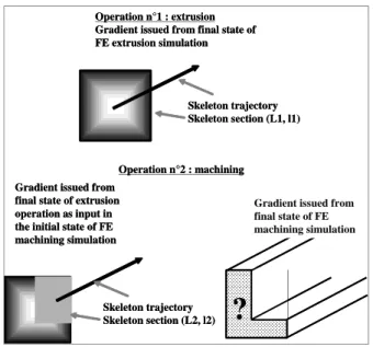
As presented in the figure 10, the difficulty currently remains in transferring each gradient from the KBE data management structure to the initial model of the simulation (most often Finite Element Simulation). Manufacturing skeletons are, indeed, not based on meshing and the gradient of information have then to be linked to topological parameters that have a strong meaning for manufacturing experts. That is not the case of any meshes that are only dedicated to specific simulation models.
Keeping the link between manufacturing parameters and product information is very useful to notify every change concerning product definition that can therefore be quickly propagated to manufacturing information without processing any new FEA.
The proposed solution based on the presented product-process interface is to link information gradient to each manufacturing skeleton which is represented by topological features and linked to manufacturing parameters (cf. Figure 10); each skeleton being adequate for each material flow of the given manufacturing operation. In very complicated cases for which information gradient cannot be explicit, a specific mesh could be associated to skeleton features; each mesh being also adequate to the specific material flow of the manufacturing operation.
Operation n°1 : extrusion Gradient issued from final state of FE extrusion simulation
Gradient issued from final state of extrusion operation as input in the initial state of FE machining simulation Operation n°2 : machining Skeleton trajectory Skeleton section (L1, l1) Skeleton trajectory Skeleton section (L2, l2)
?
Gradient issued from final state of FE machining simulation Operation n°1 : extrusion
Gradient issued from final state of FE extrusion simulation
Gradient issued from final state of extrusion operation as input in the initial state of FE machining simulation Operation n°2 : machining Skeleton trajectory Skeleton section (L1, l1) Skeleton trajectory Skeleton section (L2, l2)
?
Gradient issued from final state of FE machining simulation
Figure 10: KBE data management supporting field transfer for manufacturing simulation.
3.3- Illustration of manufacturing data management for manufacturing simulation
Figure 11 illustrates how every product-process interfaces (i.e. manufacturing skeleton) are extracted from the KBE application to be used as input information in the FE simulation. The simulation is currently processed with Zebulon as Finite Elements solver.
The first manufacturing operation consists in extruding material that create the parallelepipedic CAD model, attached tolerance and gradient as previously presented. The second operation is done with the peening forming process. The ball impact all the upper face of the part and generates plastic deformations as presented in 2.4. This simulation of the peening forming operation solving the elastic spring-back of the entire part provides the curve part presented on figure 11. The final residual stresses gradient is integrated in the manufacturing interface model to be used for potential further manufacturing operations.
Man. Operation n°1 : extrusion
• Section rectangular • Trajectory linear
Man. Operation n°2 : shot peening
• Section rectangular • Trajectory : plate
Shot peening FE simulation Man. Operation n°1 : extrusion
• Section rectangular • Trajectory linear
Man. Operation n°2 : shot peening
• Section rectangular • Trajectory : plate
Shot peening FE simulation
Figure 11: Illustration of manufacturing simulation with respect to manufacturing skeleton features.
4- Conclusion and recommendations for future work
This paper presents a product-process interface model for design for manufacturing (DFM) approach.
This model based on material flow modelling with respect to skeleton and skin concepts is first used to integrate manufacturing information as soon as possible in the product design process (i.e. “by least commitments design approach”). This integration strongly leads the CAD modelling and by the way focuses the design process on expert designers’ knowledge and not on CAD model any more.
The second objective of that interface model is to manage manufacturing information linked to product characteristics (ex: topology, tolerances, material behaviour…). It is then easy to use that link to simulate manufacturing processes taking into account the evolution of product characteristics with respect to the manufacturing plan. The whole history of each manufacturing operation is then linked to the product definition that is not currently the case in CAD centric design approach. The main perspectives for future work concern:
- The achievement of the KBE application in order to
test more complicated cases. The current developments are related to the implementation of a skeleton library and the coupling with a product-process database.
- The implementation of field transfer mechanisms to
support the whole management of the manufacturing process simulation.
5- Acknowledgment
This research work is partly supported by SNECMA
enterprise. It makes part of the MAIA8 project.
6- References
[AH1] Andreasen M., Hein L., “Integrated product
development”, Springer-Verlag, London, 1987.
[BD1] Boothroyd G. et al. Product design for manufacture and
assembly. Marcel Dekker, ISBN 0-82479-176-2, 1994.
[CR1] Cochennec F., Roucoules L., Rouhaud E., Mechanical
Analysis to identify knowledge for a DFM approach. Application to Shot Peen-forming process. In Proceedings of Virtual Concept 2006 conference, Playa Del Carmen, Mexico, 26 Nov. – 1st Dec. 2006.
[G1] Gero, J S., “Design prototypes: a knowledge
representation schema for design”, AI Magazine Vol 11 No 4 (1990) 26–36
[G2] Guagliano M. Relating Almen intensity to residual
stresses induced by shot-peening: a numerical approach. In Journal of Materials Processing Technology. 110: 267-286, 2001.
8
http://www.le-webmag.com/article.php3?id_article=2&lang=
[GA1] Grasty L. V., Andrew C. Shot peen forming sheet
metal: finite element prediction of deformed shape. In Journal of Engineering Manufacture. 210: 361-365, 1996.
[HO1] Han K., Owen D. R. J. et al. Combined finite/discrete
element and explicit/implicit simulations of peen forming process. In engineering computations, 19(1): 92-118, 2002.
[HV1] Homer S. E., VanLuchene R. D. Aircaft wing skin
contouring by shot-peening. In Journal of Material. Shaping Technologies. 0 (0): 2-8, 1991.
[KK1] Krause F.-L., Kimura F., et al., Product Modelling.,
Annals of the CIRP 42(2), 1993.
[KR1] Klein Meyer J.S, Roucoules L., De Grave A. and
Chaput J. Case study of a MEMS switch supported by a FBS and DFM framework. In proceedings of the 17th CIRP Design Conference, Berlin, 2007. ISBN 978-3-540-69819-7.
[MW1] Muh-Cerng Wu., Wu T.Y. A skeleton approach for
modelling assembly products. In Journal of Design and Manufacturing. 3: 121-133, 1993.
[R1] Roucoules L. Méthodes et connaissances : contribution
au développement d’un environnement de conception intégrée. Ph-D thesis, INPG, Grenoble, 1999.
[RD1] E. Rouhaud, D. Deslaef et al. In Handbook on
Residual Stress, Society for Experimental Mechanics, USA, 2005.
[RK1] Ramati S., Kennerknecht et al. Single piece wing skin
utilization via advanced peen forming technologies. Proceedings of the ICSP7, Warsaw, 1999.
[RL1] Roucoules L., Lafon P. et al. Knowledge intensive
approach towards multiple product modelling and geometry emergence to foster cooperative design. Proceedings of the CIRP Design seminar, Kananaskis, 2006.
[RS1] Roucoules L., Skander A. Manufacturing process
selection and integration in product design. Analysis and synthesis approaches. Proceedings of the CIRP Design seminar, Grenoble, 2003.
[RT1] Roucoules L., Tichkiewitch S. CoDE: a Co-operative
Design Environment. A new generation of CAD systems. In Concurrent Engineering Research and Application Journal (CERA) 8(4): 263-280, 2000.
[S1] Skander A. Méthode et modèle DFM pour le choix des
procédés et l’intégration des contraintes de fabrication vers l’émergence de la solution produit. Ph-D thesis, UTT, Troyes, 2006.
[S2] Sohlenius G., “Concurrent Engineering”, Annals of the
CIRP, vol. 41, n°2, pp 645-655, 1992.
[SR1] Skander A, Roucoules L., Klein Meyer JS,, Design
and manufacturing interface modelling for manufacturing processes selection and knowledge synthesis in design. In
International Journal of Advanced Manufacturing
Technology, DOI 10.1007/s00170-007-1003-2, 2007, 2007.
[T1] Thoma, J. “Introduction to Bondgraphs and their
Application”, Perga-mon Press, Oxford, 1975.
[T2] Tichkiewitch S. Specifications on integrated design
methodology using a multi-view product model. Proceedings of the ASME Engineering Systems Design and Analyse Conference, Montpellier, 1996.
[TB1] Tollenaere M., Belloy Ph., Tichkiewitch S. A part
description model for the preliminary design, Advanced CAD/CAM Systems - State-of-the-art and future trends in feature technology, pp 129-143, Chapman & Hall, Ed. Soenen, 1995.