Science Arts & Métiers (SAM)
is an open access repository that collects the work of Arts et Métiers Institute of Technology researchers and makes it freely available over the web where possible.
This is an author-deposited version published in: https://sam.ensam.eu Handle ID: .http://hdl.handle.net/10985/14896
To cite this version :
Mathieu DURAND, Frédéric HAUVILLE, Patrick BOT, Benoit AUGIER, Y ROUX, Alban LEROYER, Michel VISONNEAU - Unsteady numerical simulations of downwind sails - In: 2nd INNOV'SAIL International Conference on Innovation in High Performance Sailing Yachts · INNOV'SAIL 2010, France, 2010-06-30 - The Second International Conference on Innovation in High Performance Sailing Yachts, Lorient, France - 2010
Any correspondence concerning this service should be sent to the repository Administrator : [email protected]
See discussions, stats, and author profiles for this publication at: https://www.researchgate.net/publication/282298103
Unsteady numerical simulations of downwind sails
Conference Paper · June 2010CITATIONS 9
READS 98 7 authors, including:
Some of the authors of this publication are also working on these related projects: Development of a sub-cycling algorithm View project
Multifidelity metamodels and adaptive grid refinement for shape optimistion View project Mathieu Durand
Sirli Innovations
35PUBLICATIONS 178CITATIONS
SEE PROFILE
Frédéric Hauville
Ecole Navale de Lanvéoc-Poulmic 68PUBLICATIONS 415CITATIONS
SEE PROFILE
Patrick Bot
Ecole Navale de Lanvéoc-Poulmic 49PUBLICATIONS 316CITATIONS
SEE PROFILE
Benoit Augier
Institut Français de Recherche pour l'Exploitation de la Mer 26PUBLICATIONS 252CITATIONS
SEE PROFILE
All content following this page was uploaded by Frédéric Hauville on 04 November 2015.
THE ROYAL INSTITUTION OF NAVAL ARCHITECTS
Unsteady numerical simulations of downwind sails
M. Durand, Company K-Epsilon, Ecole Centrale de Nantes, France F. Hauville, Research Institute of the French Naval Academy, France P. Bot, Research Institute of the French Naval Academy, France B. Augier, Research Institute of the French Naval Academy, France Y. Roux, Company K-Epsilon, France
A. Leroyer, Ecole Centrale de Nantes, France M. Visonneau, Ecole Centrale de Nantes, France SUMMARY
Modelling the wind, sail and rig interactions on a sailing yacht is a complex subject, because the quality of simulation depends on the accuracy of both structural and fluid simulations which strongly interact. Moreover, the sails are submitted to highly unsteady sollicitations due to waves, wind variations, course changes or trimming for example, but sometimes also due to the unsteadiness of the flow itself (vortex shedding,…). The problem for downwind sails is even more complex because the flow is often detached from the sails, and the sails are subject to large shape changes. A specific dynamic coupling has been developed between a RANSE code from Ecole Centrale de Nantes for the aerodynamics (ISIS-CFD) and a FEM code from K-Epsilon for the structure (ARA) specialized to simulate the aero-elastic problem of yacht sails and rig. In this paper, the particular issues of coupling, remeshing and transfer of forces from one code to the other are detailed. An experimental comparison is made on a well controlled test case with an original experiment developed by IRENav Ecole Navale, consisting in a square of spinnaker fabric mounted on two carbon battens which are moved in a forced oscillation. The good agreement of numerical results with experimentals results permits to be confident to go ahead and investigate a full example of application on a racing yacht spinnaker.
1. INTRODUCTION
Unsteady computations of a sail-like membrane using a Navier-Stokes solver is really not trivial, since it requires a strong coupling between the fluid equations and the equations modelling the sail behaviour. In the present case, the Arbitrary Lagrangian Eulerian (ALE) formulation enables to reach accurate solutions, provided that the force transfert is cautiously carried out. Besides, it is essential to dispose of robust, fast and efficient volume grid deformation techniques to keep simulations with moderate CPU time. Up to now, this remains a challenging task.
This paper aims at describing the different methodologies developed to reach such a fluid/structure coupling. First results reproducing an experimental set up (a square of spinnaker fabric mounted on two carbon battens which are moved in a forced oscillation) are also presented.
2. EXPERIMENTAL SET UP
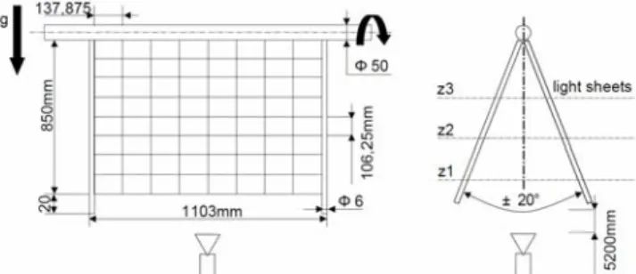
The experimental system consists in a rectangular piece of 1100 by 850mm of spinnaker sailcloth mounted on two cylindrical carbon battens which are moved in a forced periodic oscillation with no external wind. Figure 1 presents the principal dimensions of the set up. The set up is placed in a large room, so the swiveling sail is located 6m from the floor and the wall, in order to avoid any confinement phenomenon. Only the structure motion
generates a flow which affects the structure back. This simplified experiment is a good test case for the model because it reproduces most of the relevant physical phenomenon to be modeled in the aero elastic problem of yacht sails fluid structure interaction: structural deformation with large displacements, elastic flexion… Furthermore inputs are completely under control, contrarily to the case of real sailing.
Figure 1. Principal dimensions of the swiveling sail set up.
The swiveling motion consists in an oscillation around the vertical reference position with amplitude of 20 degrees. The vertical position is the 0° angular position and is the sail position at rest.
The sailcloth used is 45g/m² nylon. Its mechanical characteristics have been verified with a traction test bed in the principal directions -warp, filling- and are given in table 1. Traction tests made on a 50mm wide spinnaker
sailcloth stripes with the LBMS-MMA of Brest have shown visco-elastic behavior but requires developing a dedicated traction test procedure. A PhD student supervised by G. Bless in Brest is currently working on this subject.
Characteristics of the carbon battens have been measured and are shown in table 1.
Table 1: Sailcloth and carbon battens mechanical specification
As shown in figure 1, the carbon battens are inserted in pockets along the vertical boundaries of the sailcloth and the top ends of the battens are clamped on a rigid horizontal aluminum cylinder which is maintained by two pivots and swiveled by a permanent magnet harmonic drive CC motor FHA-25B. The angular velocity and position are controlled both by a Baldor MintDrive controller which commands the motor with high precision. The forced oscillation is characterized by the period, amplitude, rotational velocity and acceleration duration. These parameters are recorded, as shown in figure 3, and are used as input data to play the same motion with the model.
Figure 2. CC motor recorded parameters
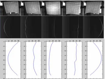
The scene is filmed with a high speed camera Photron fastcam SA3 at 250 fps to determine the shape of the moving structure along time. To easily measure the structure shape, the scene was illuminated with a horizontal light sheet and filmed from below a shown in figure 1, along the average orientation of the oscillating sailcloth. This way, the intersection of the sailcloth and the light sheet is extracted from the images. Thus the shape of the structure at a given height can be extracted. Calibration is made for each position. Figure 3 shows pictures of the light sheet shot by the fast camera from below and the results after calibration obtained after image processing with Matlab®. The 0° position given by the motor controller is used to trig the video acquisition. The light sheet is successively placed at different heights to determine the 3D shape of the structure over an oscillation period. To ensure an
established periodic regime, the first five oscillation cycles are not considered. The experimental results are compared to the numerical ones for which all the inputs are the controlled parameters of the experiment: mechanical characteristics of the structure and kinematic parameters of the forced oscillation.
Figure 3: pictures of the light sheet for a 20° oscillation amplitude shot by the camera from below. Extraction and
calibration of the stripes.
Further work is under development to measure directly the 3D shape of the structure by means of stereovision using two high speed cameras.
3. NUMERICAL METHOD
To investigate numerically aero-elastic problems that can be found with sails, two codes have been coupled: the ISIS-CFD flow solver and the ARA solver dedicated to model the structural parts of a sail boat.
3.1 The RANSE solver: ISIS-CFD
The ISIS-CFD flow solver, developed by the EMN (Equipe Modélisation Numérique) of the Fluid Mechanics Laboratory of Ecole Centrale de Nantes, uses the incompressible unsteady Reynolds-averaged Navier Stokes equations (URANSE). The solver is based on a finite-volume method to build the spatial discretization of the transport equations. The face-based method is generalized to unstructured meshes for which non-overlapping control volumes are bounded by an arbitrary number of constitutive faces. A centered scheme is used for the diffusion terms, whereas for the convective fluxes, the Gamma Differencing Scheme is used (GDS) [1] through a Normalized Variable Diagram (NVD) analysis, this scheme enforces local monotonicity and convection boundedness criteria. The velocity field is obtained from the momentum conservation equations and the pressure field is extracted from the mass conservation constraint, or continuity equation, transformed into a pressure-equation. These non-linear and coupled equations are solved by a segregated SIMPLE-like algorithm. A second-order accurate three-level fully implicit time discretization is used and surface and
volume integrals are evaluated using second-order accurate approximation. In the case of turbulent flows, additional transport equations for the modeled variables are discretized and solved using the same principles. An ALE formulation enables to deal with moving and deformable bodies [2]. The grid displacement velocity fluxes are computed to ensures the discrete space conservation law to be exactly satisfied (see [3])
Free surface flows can also be computed through an interface capturing method. [4]
This solver has been validated in numerous validation test cases in naval hydrodynamics [5] and European projects (EFFORT, Virtue...). The functionnalities, especially concerning the body motions (and the free surface for to deal with a complete sailing boat), make this solver suitable to investigate sailing problems. 3.2. The structural software: ARA
ARA is a structural mechanics code developed by the company K-Epsilon. This code is able to model a complete sailboat rig in order to predict forces, tensile and shape of sails according to the loading [6, 7, 8] 3.2(a) Matrix of Properties
The matrix of properties for a given fabric relates strain to stress. Its properties are derived from science of material or tensile tests:
[ ]
ε
σ
=
C
(8)3.2(b) Wrinkling analysis
Such a model assumes that membranes are stiff both in tension and in compression. However, for a fabric that does not have bending resistance, any type of compression results in fabric wrinkling. Following double criteria on the main tensiles and their corresponding deformations:
• “Taut State”, where
σ
min>
0
: sail completely in tension• “Wrinkled State”, case
ε
max>
0
&
σ
min≤
0
: tension in one direction only• “slack state”: sail completely in compression When wrinkles are foreseen, the direction of folds (n) and the amount of wrinkles (γ) are calculated, the relationship stress-strain becomes:
)
](
[
*
C
ε
γ
n
σ
=
+
(9)A matrix of equivalent behaviour will be used to determine the tangent stiffness:
ε
γ
ε
σ
*
=
[
C
](
+
n
)
=
[
C
*].
(10)3.2(c) Finite Elements: Spatial Integration
The nonlinear finite element formulation is established by the use of the virtual work equation.
∫
⋅
=
SdS
h
R
(
σ
*
δε
)
δ
(11)Where h is the membrane thickness, S is area of the element and δ is variation due to virtual displacement. Integration of the above equation results in a matrix of forces at each node of the domain as well as [K] tangent matrix that links the variation of forces to the variation of displacement.
The element selected for this research is the CST triangle. Despite its simplicity, this choice has proven to give a good ratio of accuracy to computing power. 3.2(d) Other elements and links
In order to represent our experimental oscillating flag a model of beam elements and a sliding model for linking elements from ARA are used to simulate battens and the sliding of the cloth on battens.
3.2(e) Structural Dynamic Scheme
The Newmark-Bossak Interaction scheme (temporal discretization) is based on a prediction-correction iterative method. The prediction is done by assuming that the acceleration remains constant. This assumption does not affect the final result.
t t t
x
x
&&
0+Δ=
&&
(12)(
)
2 0 2 0 0 0.
.
2
1
.
.
.
.
.
1
.
t
x
t
x
t
x
x
x
t
x
t
x
x
x
t t t t t t t t t t t t tΔ
+
Δ
⎟
⎠
⎞
⎜
⎝
⎛ −
+
Δ
+
=
Δ
+
Δ
−
+
=
Δ + Δ + Δ + Δ +β
β
γ
γ
&&
&&
&
&&
&&
&
&
The general equation to solve expresses as:
0
;
int
+
F
=
R
R
→
F
ernal external (13)In which the internal forces can be divided into 3 components:
(
F
inertial+
F
damping+
F
stiffness)
+
F
external=
R
(14)Deriving these as a function of position, speed and acceleration results in a Newton-type scheme:
[ ] [ ] [ ]
M
.
u
&&
+
C
.
u
&
+
K
.
u
=
R
(15)The Newmark scheme puts position, speed and acceleration in the following relation:
[ ]
K
*
.
u
=
R
(16a)[ ] [ ]
[ ]
[ ]
K
t
C
t
M
K
+
Δ
+
Δ
=
β
γ
β
.
1
.
*
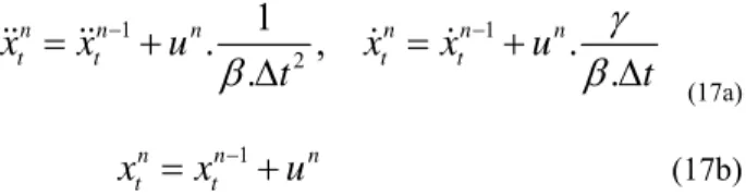
2 (16b) and:1 1 2
1
.
,
.
.
.
n n n n n n t t t tx
x
u
x
x
u
t
t
γ
β
β
− −=
+
=
+
Δ
Δ
&&
&&
&
&
(17a)
1
n n n
t t
x
=
x
−+
u
(17b)up to convergence in the structural part.
3.3. ISIS-CFD/ARA coupling
In 2002, the company K-Epsilon developed and coupled the structural code ARA with the aerodynamic code AVANTI (Unsteady Vortex Lattice Method software) [6, 7, 8]. The less CPU time of the UVLM software has enabled us to develop and validate specific algorithms for FSI on membrain (software ARAVANTI). Both the algorithms and the philosophy of the coupling of ARAVANTI were applied to the URANSE code ISIS CFD and ARA.
3.3(a) Fluid/Structure coupling
Figure 4: implicit coupling diagram
An implicit/iterative algorithm (see Fig.4) is used to coordinate the data exchanges between the fluid and structure solvers and obtain a stable coupling. This algorithm is structured into three hierarchical loops. The highest level corresponds to the temporal loop. The second one, denoted here the FSI loop, aims at solving
the non-linearity’s of the fluid problem (it correspond to the non-linear loop when dealing with non-FSI computations). In the case of FSI computation, the dashed box in Fig.4 is added. In particular, it includes the resolution of the structure problem (structure loop). Thus, at each new FSI iteration (where the time is fixed), the structure problem is solved until convergence on the geometric non-linearities using the current fluid loads. It can be done at each FSI iteration, since the CPU time of the structure resolution is negligible compared to that of the fluid resolution. The geometry and kinematics of the configuration are then updated. In particular, an adjustment of the fluid mesh is carried out to recover a body-fitted mesh. At that time, the core of the fluid solver is called to obtain a new evaluation of the current flow (inducing new values of fluid loads for the structure). A new non-linear iteration can thus restart. This coupling process (FSI loop) is repeated until convergence of the fluid flow. Then, a new time step can go on.
Even if fluid/structure exchanges are performed during the resolution of the fluid within the same time step special attention has to be paid for the evaluation of [K*] to reach a stable coupling (see eq. 16), since fluid/sail interaction is very strong
In fact, if Fext (i.e. Fluid forces) is considered as a constant (independent of x and its derivatives), as it is classically done for weaker FSI problems (in this case, [M], [C] and [K] only depend on the structure properties), divergent oscillations quicky appear. To ensure stability, a specific approximation of [K*] taken into account the dependancy of Fext onto x is required. More precisely, an approximation of the inertia matrix of the fluid denoted [M_fluid] (which is the predominant fluid term for such a problem) has to be integrated into [K*] in addition to the contribution of the structure. This matrix [M_fluid] is computed using an invisid flow solver (integrated aside the ARA solver).
3.3(b) Grid deformation techniques
Ad-hoc deformation techniques have thus been developed to keep a body-fitted mesh during its motion. One is based on a pseudo-structure approach to build a consistent and robust unstructured grid deformation strategy. The fluid domain is considered as a linear elastic solid structure obeying structural equations which are linearised and used even in the case of large deformations. The non-uniform local orthotropic behaviour enables to control the quality of the mesh and to enhance the robustness. This method is only used once per time step when the deformations are significant. Inside the FSI loop, an analytical weighting technique has been developed to adjust the new shape of the structure to the fluid domain and then recover a body-fitted mesh with an insignificant CPU time. It is based as an extension of weighting techniques implemented for rigid bodies and beam-like bodies. The idea is to diffuse the rigid motion of each fluid face belonging to the bodies inside the fluid domain, layer by layer. The notion of layer is defined during the initialization of the
simulation using a criteria based on the shorter way to reach the face. Then, the computed displacement of each node is damped using a weighting coefficient which decreases up to zero when going far away from the body. 3.3(c) Force transfer
Even if both structure and fluid meshes are generated from the same geometry, an extrusion of the geometric definition of the surface is needed to obtain a suitable boundary for the fluid mesh, whereas only a 3-D surface is required for the structure mesh. Furthermore, the meshing procedure is not identical for both, so as to the location of the variables (structure variables are located at the nodes, whereas fluid variables are cell-centered). A redistribution of the fluid force applied on each fluid face is then needed. This is done through a conservative way. The first step concerns the splitting of fluid faces which cut structure faces. Fluid forces are thus weighted according to their respective area. Next, the distribution of forces are broadcasted towards the nodes of the considered structure element: this step is done by writting the force and momentum balances (see Fig.5)
Figure 5 : force transfer procedure
4. RESULTS
Here comparisons between video from IREnav and computations of the same benchmark are presented. The figure 6 shows two particular events: when cloth of the edge is not in a taut state with an angular shape, and when cloth is in a taut state with a curvature edge. For both events, the shape looks similar, in particular simulations manages to capture the inflexion near the edge.
Figure 6: comparison video / computations
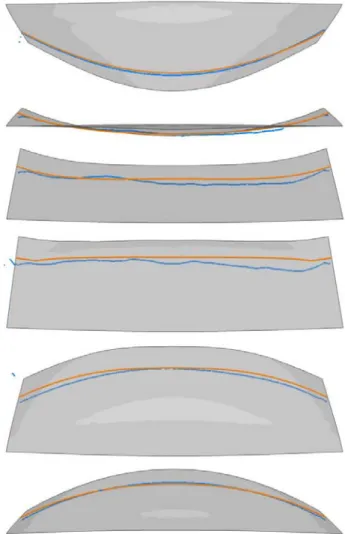
Figure 7 shows comparisons of the experimental light sheet (blue line) with the computation of intersection between constant plane and cloth (orange line). This result shows a really good accordance during all the motion of the cloth.
Figure 7: comparison experimental (blue) / computation (orange) of a section of the cloth
5. CONCLUSIONS
Numerical methodologies which have been described make possible to deal with simulation involving unsteady
configuration around sails using a RANSE solver based on an ALE formulation:
• the implicit/iterative coupling associated with an evaluation of the surface added mass of the surrounding fluid makes the fluid/structure stable,
• the grid deformation techniques implemented into the fluid solver enable to recover a body-fitted mesh each time it is needed without increasing too much the cpu time compared to a classical CFD computation (indeed, inside the FSI loop, the analytical weighting regridding has negligeable cpu time)
• the conservative force transfer ensures an accurate procedure
Results on an experimental set up carried out in laboratory confirm robustness of the whole procedure. More detailed validations are planned with this case: Comparisons of 3D shape when the new experimental post-treatment is available so as comparison of global fluid force.
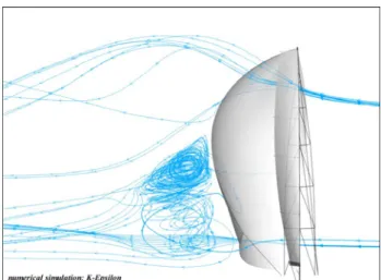
Computations dealing with realistic configurations (like in Fig 8 which shows a configuration around a racing yacht spinnaker) are now in progress too. Comparisons with different experimental data, especially data coming from in-situ measurements (instrumented J80 sailing boat) are also planned.
Figure 8 : result of a complete IFS on a spinnaker
6. REFERENCES
[1] JASAK, H. and WELLER, H.G. and GOSMAN A.D. , ‘High resolution NVD differencing scheme for arbitrarily unstructured meshes’, International Journal
for Numerical Methods in Fluids, Vol 31, pp.431-449,1999
[2] LEROYER, A. and VISONNEAU, M., ‘Numerical methods for RANSE simulations of a self-propelled fish-like body’, J. Fluid & Structures, Vol. 20, No. 3,
pp.975-991 , 2005.
[3] LEROER, A. and BARRE, S. and KOBUS, J.M. and VISONNEAU, M. ‘Experimental and numerical
investigations of flow around an oar blade’, Journal of
Marine Science and Technology, volume 13,1-15, 2008
[4]. QUEUTEY, P. and VISONNEAU, M., ‘An interface capturing method for free-surface hydrodynamic flows’,
Computers & Fluids, Vol. 36, No. 9, pp.1481-1510,
2007.
[5] GUILMINEAU, E. and QUEUTEY, P. and VISONNEAU, M. and LEROYER, A. and DENG, G. ‘RANS simulation of a US Navy frigate with PMM motions’, Workshop on Verification and Validation of
Ship Manoeuvering, Simulation Methods, SIMMAN 2008, Copenhagen, Avril 2008
[6] Durand, M., Hauville, F., Mounoury, S. and Roux, Y., 2007. - Comparaison des résultats d’un modèle aéroélastique appliqué à la déformation d’un gréement avec des mesures en soufflerie et in situ - In 11èmes Journées de l'Hydrodynamique, Brest, ENSIETA, 3-5 Avril, 2007, pp 185-198.
[7] Y.Roux, M. Durand, A. Leroyer, P. Queutey, M. Visonneau, J Raymond, J. M. Finot, F. Hauville, A. Purwanto. ‘Strongly coupled VPP and CFD RANSE code for sailing yacht performance prediction’. High Performance Yacht Design Conference, Auckland, December 2008, pp 215-225
[8] Hauville, F., Durand, M., and Roux, Y., 2007, Modèle aéroélastique appliqué à la déformation d’un gréement. European Journal of Environmental and Civil Engineering, 2008, Vol. 12, No 5, pp 549-560
7. AUTHORS BIOGRAPHY
Mathieu Durand is Researcher Student within the K-Epsilon company since 2008 and preparing his PhD with Ecole Centrale de Nantes and IRENav. His work deals with numerical FSI modelling. He is also a top 100 match racer sailor.
Frederic Hauville and Patrick Bot are associate professors at IRENav, specialised in fluid mechanics. They are studying Fluid Structure Interaction and marine renewable energy. They have been working on FSI of sails for many years and started to develop measurements on sailing yachts in 2000.
Benoît Augier is PhD student in the Research Institute of the French Naval Academy (IRENav). He is studying the Fluid Structure Interaction on soft surfaces with a strong application to sails. He is particularly in charge of the experimental work.
Yann Roux holds the current position of C.E.O. at the company K-Epsilon and is the main founder. In partnership with the laboratory Ecole Centrale de Nantes and IRENav, he develops software and customised tools
and provides studies and service in unsteady hydrodynamic and aerodynamic computation.
Alban Leroyer is Assistant Professor at the Fluid Mechanics and Energetics Department of ECN since 2005. He is carrying out its research within the CFD department of the ECN Fluid Mechanics laboratory. His research topics include Naval Hydrodynamics, Fluid-Structure Interaction and Bio-Hydrodynamics.
Michel Visonneau is Research Director within CNRS since 2006. He is currently the head of the CFD department of the Fluid Mechanics Laboratory (ECN) in 1995. His main research topics are Computational Fluid Dynamics (CFD), Ship Hydrodynamics and Turbulence Modeling for high Re flows. He has been selected as 30th Georg Weinblum Memorial Lecturer (2007-2008).
View publication stats View publication stats