Biomedical Engineering. This article’s citation is as follows:
Seoud, L., Cheriet, F., Labelle, H. and Dansereau, J., “A Novel Method for the 3-D
Reconstruction of Scoliotic Ribs from Frontal and Lateral Radiographs.” IEEE
Transactions on Biomedical Engineering, Vol. 58, No. 5 (2011), pp.1135-1146.
doi: 10.1109/TBME.2009.2032530
The manuscript, as accepted by the publisher, is reproduced in the following pages.
© 2011 IEEE. Personal use of this material is permitted. Permission from IEEE must be
obtained for all other users, including reprinting/republishing this material for advertising
or promotional purposes, creating new collective works for resale or redistribution to servers
or lists, or reuse of any copyrighted components of this work in other works.
Abstract— Among the external manifestations of scoliosis, the rib hump, which is associated to the ribs’ deformities and rotations, constitutes for patients the most disturbing aspect of the scoliotic deformity. A personalized 3D model of the rib cage is important for a better evaluation of the deformity and thus, better treatment planning. A novel method for the 3D reconstruction of the rib cage, based only on two standard radiographs, is proposed in this article. For each rib, two points are extrapolated from the reconstructed spine, and three points are reconstructed by stereo radiography. The reconstruction is then refined using a surface approximation. The method was evaluated using clinical data of 13 patients with scoliosis. A comparison was conducted between the reconstructions obtained with the proposed method and those obtained using a previous reconstruction method based on two frontal radiographs. A first comparison criterion was the distances between the reconstructed ribs and the surface topography of the trunk, considered as the reference modality. The correlation between ribs axial rotation and back surface rotation was also evaluated. The proposed method successfully reconstructed the ribs of the 6th to 12th thoracic levels. The evaluation results showed that the three dimensional configuration of the new rib reconstructions is more consistent with the surface topography and provides more accurate measurements of ribs axial rotation.
Index Terms—3D reconstruction, Rib cage, X-rays, Surface
topography.
I. INTRODUCTION
COLIOSIS is a three-dimensional deformity of the spine and the rib cage, leading to a general asymmetry of the trunk. The most frequent type of scoliosis, idiopathic scoliosis, has no specific identifiable cause. It is most commonly a condition Manuscript received February 28, 2009. This work was supported by the Natural Sciences and Engineering Research Council of Canada and MENTOR, a strategic training program of the Canadian Institutes of Health Research.
L. Seoud is with Sainte-Justine Hospital Research Center and École Polytechnique de Montréal, Montreal, QC H3C 3A7, Canada (e-mail: lama.seoud@polymtl.ca).
F. Cheriet is with Sainte-Justine Hospital Research Center and École Polytechnique de Montréal, Montreal, Canada.
H. Labelle is with Sainte-Justine Hospital, Montreal, Canada.
J. Dansereau is with Sainte-Justine Hospital Research Center and École Polytechnique de Montréal, Montreal, Canada.
Copyright (c) 2008 IEEE. Personal use of this material is permitted. However, permission to use this material for any other purposes must be obtained from the IEEE by sending an email to pubs-permissions@ieee.org.
of adolescence that progresses during the growth spurt. Among the adolescent population, the incidence of adolescent idiopathic scoliosis (AIS) is 4.5 per cent [1]. In the absence of treatment, it may lead to postural problems, and even cardiac or pulmonary complications.
Usually, the evaluation of scoliosis relies on frontal and lateral radiographs, on which several 2D measurements are computed. Most importantly, the Cobb angle, defined as the angle between the end plates of the two most tilted vertebrae along the spinal curve [2], represents a scoliosis severity index when measured in the frontal plane. Nevertheless, in the past fifty years, many studies [3-5] have documented the three-dimensional aspect of scoliosis and emphasized the importance of a 3D evaluation.
Common 3D imaging modalities, such as magnetic resonance imaging (MRI) or computerized tomography (CT), are not suitable for the 3D evaluation of scoliosis, mainly because such images are usually acquired in the supine position and thus do not represent the natural posture of the spine. Furthermore, the MRI acquisition is time consuming, expensive and is not recommended for patients with surgical implants. As for the CT, the imaging of the whole trunk implies, for the patient, an important exposure to ionizing radiations, making it unsuitable for this kind of application. Thus, stereo-radiography is and remains the most frequently used technique for 3D reconstruction of the spine, the rib cage and the pelvis.
Over the last three decades, a large number of studies have focused on the scoliotic three-dimensional deformity of the spine. Consequently, several stereoradiographic reconstruction techniques have been proposed [6-16], varying mainly in terms of calibration method, X-ray configuration, reconstruction primitives and algorithm. All these different techniques provide a 3D model of the spine, according to which several 3D clinical parameters are computed and used for diagnosis, follow-up or correction assessment of the spinal deformity. The geometric reconstruction can also be combined with mechanical properties of the vertebrae to build a biomechanical model of the spine that can be used, for example, in treatment simulations.
Nevertheless, AIS is more than just a deformity of the spine. It also implies considerable changes to the rib cage three-dimensional configuration, mainly the axial rotation of the ribs to which is associated the rib hump. Considered as one
A Novel Method for the 3D Reconstruction of
Scoliotic Ribs from Frontal and Lateral
Radiographs
Lama Seoud, Farida Cheriet, Ph.D., Hubert Labelle, M.D., and Jean Dansereau, Ph.D.
of the first visible symptoms of AIS [17-19], this protuberance appears on the back of the patient, most prominently while bending forward. Its measurement using a scoliometer (Fig. 1) has made it possible to implement school screening programs for early diagnosis of scoliosis [20]. Although the rib hump is a very disturbing aspect of the deformity for the patient [21], it is still weakly understood. In fact, the relationship between the spine and rib cage deformities is not yet clearly defined. Some studies have shown a correlation between ribs axial rotation and vertebrae axial rotation [5, 17, 22, 23], while no significant correlation has yet been found between the Cobb angle and the ribs axial rotation [17, 19, 22, 23]. Furthermore, since the rib cage deformity is not clearly understood, there are also problems in correcting the rib hump. The rib cage deformity often persists after spine surgery, and consequently patients are often still dissatisfied with their appearance [24]. Moreover, considering that there is still no generally accepted theory for the etiology of idiopathic scoliosis [25, 26], some researchers postulate that the rib cage deformity comes prior to the spine deformity in the pathogenesis of scoliosis [26-28].
Compared to the spine, fewer techniques for the 3D reconstruction of the rib cage have been reported in the literature. The first reported method [29] is based on two postero anterior radiographs of the trunk in the standing posture: PA and PA20. The use of those radiographs is justified by the good visibility of the ribs as opposed to the lateral view. The method requires an operator to manually identify 11 points along each rib midline in each radiograph. These points are then interpolated by cubic splines. Then, 60 points are discretized along each spline. The DLT algorithm is then applied for the stereo matching of the points between the two radiographs and for the reconstruction of the points in 3D. This method has been subsequently improved by incorporating patient displacement between the two X-ray acquisitions [30]. However, the poor disparity between PA and PA20 leads to
reconstruction errors, specifically in depth estimation [31]. In fact, an extensive in-vitro evaluation of the reconstructions of a cadaveric spine specimen demonstrated that the accuracy obtained with the PA-PA20 setup is 5.6 ± 4.5 mm, compared to 2.1 ± 1.5 mm in the case of the PA-LAT setup [31]. Moreover, in order to reconstruct in 3D both the spine and rib cage, three radiographs (PA, PA20 and LAT) are required. This increases the patient’s exposure to radiation and thus limits its clinical application.
To overcome these problems, other methods based on the LAT and PA radiographs have been proposed [32-34]. However, the significant overlapping of the bony structures in the LAT view reduces the ribs’ visibility considerably. To compensate this lack of information, these methods make use of a priori 3D models of the ribs [32] or of the entire rib cage [33, 34]. These models are iteratively deformed until the optimal registration between the projection of the model and the X-ray image of the structures is reached. In two of these studies [32, 33], the models were obtained statistically using a database of ribs [32] or rib cages [33] reconstructed by the method in [29], of which we have previously shown the limitations. For the method in [34], the generic rib cage is obtained from a CT-scan reconstruction. Still, a single rib cage model cannot correctly approximate all the variety of scoliotic deformities. The accuracy of the method in [34] was then evaluated in vitro [35], by comparing 3D reconstructions obtained from 50 cadaveric ribs to the CT scan reconstructions of the same ribs. However, an in vitro study simplifies the problem related to structures deformability and patient’s motion due to breathing.
In the objective of reconstructing the 3D geometry of scoliotic ribs, with special concerns for reducing patients’ exposure to radiation and obtaining more accurate reconstructions than in [29], we propose in this paper a new method for the 3D reconstruction of scoliotic ribs, based on two standard radiographs, namely the LAT and PA, and without an a priori 3D model. We also present an evaluation of the reconstructions obtained with the proposed method, in comparison to those obtained with the method in [29].
The remainder of this manuscript is divided into five sections. Section II presents the method proposed for the 3D reconstruction of scoliotic ribs. Section III outlines the clinical experiments and the evaluation method. Then, some sample reconstructions are illustrated in section IV, as well as the evaluation results. The strengths and weaknesses of the proposed method and the associated evaluation experiments are discussed in section V. Finally, section VI provides a conclusion and states the perspectives and future work.
II. MATERIALS AND METHODS
Our novel method for the three-dimensional reconstruction of scoliotic ribs is described in this section. The materials, acquisitions and pre-processing are presented in a first subsection. Subsection B outlines the 3D reconstruction of the rib insertion points. Subsections C and D describe respectively the identification of the ribs in the PA and LAT radiographs, and the reconstruction of three stereo corresponding points Fig. 1 - The rib hump appears on the back of the scoliotic patient while
bending forward. The severity of the rib hump is measured using a scoliometer, a device that quantifies the height difference, in terms of an angle, between the right and left sides of the back.
along each rib. Finally, we present in the last subsection the method used to refine the reconstruction of the ribs.
A. X-rays acquisition and 3D reconstruction of the spine The reconstruction method proposed in this paper relies only on a pair of standard radiographs, LAT and PA, of the whole trunk in upright position. As part of the standard clinical assessment of scoliosis, these X-rays are commonly acquired for patients attending the scoliosis clinic at Sainte-Justine Hospital (SJH), Montreal, Canada, using a Fuji FCR7501S imaging system (Japan). A rotary platform allows the technician to bring the patient from the LAT to the PA position. A stabilization device composed of elbow supports and handlebars is used to prevent posture and position changes due to the patient’s involuntary movements during both acquisitions [36]. The technician adjusts the height of the elbow support so that the upper arms are angled down approximately 45°. For calibration purposes, the patient wears a jacket with 16 embedded radio-opaque markers during the acquisitions. The setup also includes an external planar plate that defines a global reference frame for the 3D reconstructions.
The radiographs are then explicitly calibrated by means of a non-linear optimization process [7]. Next, according to the method in [8], 6 anatomical landmarks per vertebra are manually identified in each X-ray and reconstructed in 3D. These points constitute patient-specific information on the geometry of the vertebrae. Generic vertebral models are then adjusted to each set of 6 reconstructed points in order to complete the geometry [9]. Additionally, this adjustment process associates to each reconstructed vertebra a more complete set of anatomical landmarks.
B. Extraction of rib insertion points
According to rib cage anatomy [37], each rib from the first to the tenth thoracic levels (T1-T10) is articulated with the thoracic vertebra of the same level, in two points: the head of the rib and the tubercle. The head (Head) of the ith rib lies
between the superior articular facet (SAF) of the body of ith
thoracic vertebra and the inferior articular facet (IAF) of the body of the (i-1)th thoracic vertebra. The tubercle (Tub) of the ith rib is articulated to the articular facet of the transverse
process (AFTP) of the ith thoracic vertebra (Fig 2).
Based on this knowledge and using several anatomical landmarks on the reconstructed vertebrae, the midpoints on the head (H) and tubercle (T) of each rib are computed using the following equations:
2
)
(
1, , ,j i j ij iIAF
SAF
H
=
−+
(1) j i j i j ic
d
n
T
,=
,+
.
r
, (2) with i and j corresponding respectively to the thoracic level (i=1, …, 10) and the side of the rib (j=1, 2 for left and right); ci,jis the centroid of the N landmarks constituting the AFTP,n
r
is the normal vector to the least squares plane that fits the N points and d is the average distance between c and T. This distance was fixed at 7.09 mm, based on measurements done with a coordinate measuring machine on 6 cadaveric ribs [38].The atypical ribs of levels T11 and T12 are articulated to the spine only at their heads that are directly connected to the superior plates of the vertebrae of the same levels [37]:
j i j
i
SAF
H
,=
, (3) with i and j again corresponding respectively to the thoracic level (i=11,12) and the side of the rib (j=1,2 for left and right). The projection of each extracted head and tubercle in the LAT and in the PA helps to locate each thoracic level in the radiographs.C. Identification of the rib midlines in the PA
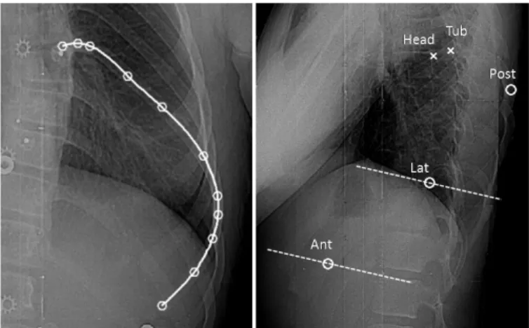
The next step of the reconstruction process consists in identifying all the rib midlines in the PA, since this X-ray makes it possible to clearly distinguish the ribs over their whole length. To this end, an experimented operator manually identifies 11 points on each rib midline, as in [29]. These Fig. 2 - Extraction of the head (black star) and tubercle (black square) of a
typical rib. a) Anatomical representation of the costo-vertebral articulations (adapted from [39]). b) 3D complete model of the vertebrae (light gray), with the articular facets (dark gray), and the extracted insertion points (black) of the considered rib midline (black dashed line).
Fig. 3 – On the left: rib midline identification in the PA: 11 points (white circles) are manually identified along the rib midline then a cubic spline is fitted along the 11 points. On the right, identification of rib points in the LAT: the two insertion points (white crosses) are projected in the LAT in order to locate the given thoracic level. Then, three points (white circles) are identified manually. The dashed lines represent the epipolar lines corresponding to the Lat and Ant points in the PA view.
points are then fitted by cubic splines and 60 points are sampled on each curve (Fig. 3).
D. Identification of three rib points in the LAT and their 3D reconstruction
The overall rib reconstruction process consists in successively reconstructing the pairs of ribs (left and right), starting from the 12th thoracic level and moving upward, and
considering as many visible ribs in the LAT as possible. In fact, the ribs’ visibility is much weaker in the LAT than in the PA. This is attributed to the considerable overlap of the bony structures through this X-ray incidence and to the positioning of the upper arms of the patient during the radiographic acquisitions. Therein, only 3 specific points on each rib midline need to be manually identified in this radiograph, as follows.
1) Most posterior point: the first specific point to identify is the most posterior point (Post) of each rib; it is easily identified in the LAT. However, the principal difficulty at this
step is to distinguish, at each thoracic level, the Post of the left rib from the one of the right rib. To simplify this task, knowledge of the spatial configuration of the rib hump is exploited. In fact, it is commonly assessed that the rib hump arises on the convex side of the lateral curvature of the spine [17]. Thus, by examining the curvature of the spine in the PA radiograph, the spinal curve is classified [39] and the rib hump configuration can then be determined. According to the level and the side of the rib hump, we can now label each Post (for the left and right ribs) of a given thoracic level. Indeed, the right-most of the two posterior points in the LAT image will correspond to the rib on the same side as the hump. To illustrate this, Fig. 4 presents typical cases of two different scoliosis types. For the double thoracic curve (on the right in Fig. 4), the PA radiograph reveals two major curves in the thoracic region: the first one between T1 and T7 is deviated to the left; the second one between T7 and T11 is deviated to the right. Thus, two rib humps arise: h1 appears on the left side of the patient between T1 and T7, and h2 appears on the right side between T7 and T11. In the LAT view, the most posterior points of each rib is identified manually (represented by stars in Fig. 4). As h1 is on the left side, the right-most stars between T1 and T7 (in white) thus correspond to the left ribs, while the left-most stars (in dark gray) correspond to the right ribs. Between T7 and T11, the sides are reversed because h2 is on the right side.
Once the Post of a rib is identified in the LAT and correctly labeled, an algorithm automatically seeks its corresponding point in the PA, defined as the point of the given rib’s midline that is closest to the associated epipolar line. Once the stereo pair is found, the 3D position of the Post is determined by finding the intersection of the projection rays of the two image points. When the rays do not intersect, the midpoint of the smallest segment joining the two rays is considered.
2) Anterior end and most Lateral point: the two other points
Fig. 4 - Identification of the most posterior rib points in the LAT, for a right thoracic curve (on the top) and a double thoracic curve (at the bottom).
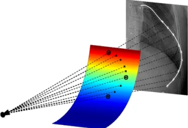
Fig. 5 - Refining the reconstruction: Post, Lat and Ant are already reconstructed in 3D (black circles). A paraboloid is fitted to these points (multicolor surface). M points are discretized (white crosses) on the rib midline between the Post and the Ant in the PA view. The M projection rays (dashed black lines) intersect the paraboloid in M 3D points (black crosses). These 3D points, combined with the Head, Tub, Post, Lat, and Ant, constitute the reconstructed rib midline.
to identify in the LAT are the anterior end (Ant) and the most lateral point (Lat) of the rib. These are readily identifiable points in the PA: the lower end and the most lateral point of each midline curve. To help the operator to identify them in the LAT, the epipolar lines corresponding to the points in PA are displayed in the LAT successively for the left and right ribs of each thoracic level (Fig. 3). Once these points are manually selected in the LAT and matched with the corresponding points in the PA, their 3D positions are obtained by finding the intersections of the projection rays.
The eleventh and the twelfth pairs are “floating” ribs [40]: their anterior ends are not connected to the rest of the rib cage and these ribs are shorter than the others. Consequently, the anterior end and the most lateral point of each of these ribs represent exactly the same point. Thus, only the Post and Ant points are digitized in the LAT and reconstructed in 3D. E. Reconstruction refinement
At this stage, five points have been reconstructed in 3D along the typical ribs (between levels T1 and T10). The following step consists in refining each rib by adding sufficient points in order to interpolate it by a 3D cubic spline representing the rib midline. To do so, a rib-specific 3D reference frame is built around the five previously reconstructed points, as follows: the reference frame is centered on the centroid of the last three reconstructed points (Post, Lat and Ant), the first axis (u-axis) is defined by the vector joining the Lat and the Ant points, the second axis (w-axis) is defined as the normal vector to the least squared plane that fits the five reconstructed points (Head, Tub, Post, Lat and Ant), and the third axis (v-axis) is defined as the cross-product of u and w axis. In this reference frame, a paraboloid passing through the Post, Lat and Ant points is defined as:
w
c
bu
au
2+
+
=
. (4) The rib midline is then constrained to fit within that surface. The choice of a paraboloid surface is justified by the parabolic shape of the ribs (from the Post to the Ant) in the LAT view. Still, the curvature of this surface along the w-axis is weak. In fact, while trying to characterize the global geometry of human ribs [41], it has been noted that the rib portion that goes from the angle (most posterior part) to the costochondral junction (anterior end) lies “substantially” in one plane, while the portion that goes from the head to the angle lies “substantially” in another plane.Then, considering M points between the projections of the Post and the Ant along the rib midline in the PA, the algorithm seeks the intersections of the paraboloid with the M projection rays; M 3D points are thus obtained (Fig. 5). Finally, a cubic spline is fitted to all the reconstructed points: Head, Tub, Post, Lat, Ant and the M points. This spline represents the rib midline in 3D.
For the floating ribs of level T11 and T12, because of their relatively smaller length, a cubic spline interpolation of the three reconstructed points (Head, Post and Ant), is sufficient to model their midlines.
III. EVALUATION METHOD
We will evaluate the reconstructions obtained by the proposed method (Rnew) by comparing them with the reconstructions obtained by the method used at SJH (Rold), based on [29]. The reference modality is the surface topography of the trunk, acquired using a totally non invasive technique. Two comparison criteria are proposed: the distances between the reconstructed ribs and the trunk surface topography, and the correlation between ribs axial rotation and back surface rotation. These criteria reflect how well the reconstructions are consistent with the surface topography of the trunk.
A. Acquisition of the surface topography of the trunk
Because Currently at SJH, the acquisition of the surface topography uses the InSpeck system [42]. It is composed of four optical digitizers placed around the patient who maintains the anatomical position with the arms in slight abduction by the side. This posture minimizes the occlusion of the digitizers field [43]. Each digitizer reconstructs the surface topography of one side of the trunk. Given a calibration matrix, the four reconstructed surfaces are registered together and merged to obtain the surface topography of the entire torso. In order to assess the accuracy of the trunk surface 3D reconstruction, repeated acquisitions of a mannequin were performed [44]. Thirty nine markers were fixed on its trunk and their 3D coordinates were measured with a coordinate measuring machine (CMM). They constituted the ground truth. The accuracy of the trunk surface reconstruction was of 1.1±0.9 mm over the entire trunk surface. Moreover, repeated trunk surface acquisitions using the InSpeck system, for 49 scoliotic patients in two different postures, were carried out in order to assess the reliability of the extracted indices [43]. Several measurements including back surface rotation were computed on each patient’s reconstruction. The statistical analysis showed a fair to excellent reliability for the anatomical position and a back surface rotation typical measurement error of 1.4°.
Thus, considering the accuracy and reliability of the trunk
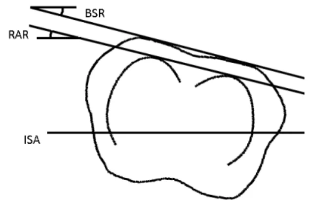
Fig. 6 - Description of the back surface rotation (BSR) and the ribs axial rotation (RAR) in an axial projection of the ribs of a given level and the corresponding section of the surface topography. BSR is the angle defined by the dual-tangent to the posterior part of the topography section and the iliac spines axis (ISA). RAR is the angle defined by the dual-tangent to the posterior part of the reconstructed ribs and the anterior superior iliac spines axis (ISA).
surface 3D reconstruction using the InSpeck system, and bearing in mind that this technique is totally non invasive, we believe that its use as a reference modality is appropriate for the evaluation of our rib cage 3D reconstruction technique. B. Clinical data
A clinical study using real data from scoliotic patients attending the SJH scoliosis clinic was conducted. Included in our study were subjects who had their X-rays (PA, PA20 and LAT) and the surface topography acquired during the same consultation, and the rib cage previously reconstructed by the method in [29] (Rold). We selected the data of 13 adolescents
with AIS who matched the inclusion criteria. Among this cohort, the average Cobb angle and the mean age recorded at the time of consultation were respectively 36° (±8°) and 12.7 years (±1 year).
The proposed reconstruction method was applied to each patient (Rnew). A single operator was in charge of the LAT
digitization. For the purpose of comparison with Rold, the same
11 points per rib, previously identified in the PA, were considered.
C. Registration
Since evaluation of the reconstructions is based on their consistency with the surface topography of the trunk, the first important step consists in registering the 3D reconstructions and the surface topography in the same reference frame. The reconstructed spine and rib cage are defined in a first reference frame, noted RRX, and the surface topography in a second
reference frame, RTP. Approximately 15 to 20 radio-opaque
markers are placed on the patient’s trunk before both acquisitions. Their distribution is as regular as possible in order to improve the registration precision. These markers constitute the only common information to both acquisitions. Visible in the radiographs, they are reconstructed in 3D in RRX; visible as well on the surface topography, their 3D
positions in RTP are retrieved.
As a first attempt, a rigid registration is carried out to merge the reconstructions together. However, the radiographic and topographic information are acquired at different times, in different rooms and with different patient postures. To take into account the patient’s displacement between both acquisitions, an elastic registration based on approximating thin-plate splines [45] is also performed. It consists in determining the mapping that minimizes the following functional:
( )
( )
u
J
p
u
q
n
u
J
md n i i i iλ
σ
λ+
−
=
∑
=1 2 21
)
(
(5)The first term of this functional measures the sum of the quadratic Euclidean distances between the transformed landmarks and the landmarks . Each distance is weighted by the variance representing landmarks localization errors. For all the landmarks, the variance was fixed at 1.1 which corresponds to the accuracy of the trunk surface reconstruction. The second term in (4) measures the smoothness of the transformation. The relative weight
between both the approximation and smoothness terms is set by the regularization parameter . Based on empirical tests, the regularization parameter is set to in order to limit undesired distortions of the trunk surface.
D. Distances between the ribs and the surface topography A first evaluation step consists in the 3D visualization of the complete trunk model of each patient: bony structures and registered surface topography (Rnew versus Rold). Then, in
order to evaluate the distances between the reconstructed ribs and the external surface, the rib midlines are discretized at intervals of 2 mm. For each point, the minimal signed distance (noted d) between the current rib point and the nearest point on the surface topography is computed. A negative value of d indicates that the rib midline protrudes from the surface topography at some point. Moreover, the mean distances for each portion of the rib are evaluated: along the head and tubercle (P1), the posterior part (P2), the lateral part (P3) and the anterior part (P4). For the ribs of levels T11 and T12, we considered only parts P1 and P2, and for the ribs of level T10, only parts P1, P2 and P3 were considered. A Student’s t test is performed in order to test the null hypothesis that there is no difference between the means distances obtained for Rnew and
Rold.
E. Correlation between ribs axial rotation and back surface rotation
Thereafter, the reconstructions Rnew and Rold are compared
in terms of the correlation between the internal and external rib humps (Fig. 6). The internal rib hump is measured as the ribs axial rotation (RAR). Expressed in degrees, it is defined as the angle formed by the dual-tangent to the ribs of a given level and the axis passing through the anterior superior iliac spines (iliac spines axis or ISA), projected onto the axial plane. The external rib hump is measured as the back surface rotation (BSR). Also expressed in degrees, it is defined as the angle formed by the dual-tangent to the posterior side of each section of the trunk surface topography and the ISA, projected onto the axial plan. At each thoracic level, the trunk section is computed as the intersection of the surface topography with a tilted plane defined by the most posterior points of each rib of the thoracic level considered. Both measures are computed automatically without any operator intervention.
For both Rnew and Rold, the correlations between the internal
and external rib hump are quantified by the Pearson’s coefficient (R), using a linear regression analysis. The correlation is considered as statistically significant if p<0.01. The coefficients of determination are obtained by R2. The data
dispersion around the trend line is quantified by the standard deviation of the residuals.
IV. RESULTS
Out of the whole cohort, a total of 164 ribs (82 pairs) were successfully reconstructed by the proposed method. The number of reconstructed ribs varies from one patient to another as well as between thoracic levels (Fig. 7). On average, 7 (±1) pairs of ribs were reconstructed per patient
from levels T6 to T12, which constitutes the lower half of the rib cage. The upper half of the rib cage had poor visibility in the lateral radiographs.
Fig. 8 presents a visual comparison in 3D between the rib midlines of a typical patient chosen from the cohort, obtained with the proposed method and the method in [29]. After registrating the surface topography and the reconstructed bony structures, a 3D model of the trunk is obtained, as in Fig. 9. In this figure, it can clearly be seen that several ribs from Rold
protrude from the external surface of the trunk, while none of the Rnew ribs protrude.
A. Distances between the ribs and the surface topography TABLE I summarizes the number of protruding ribs and the length of the protrusions, along each portion of the ribs: the head (P1), posterior (P2), lateral (P3) and anterior (P4) portions for both the rigid and elastic registration. A rib is protruding if at least one point along its length is at a negative distance d from the surface topography. The length of the protrusions is defined as the number of points per rib that are at a negative distance d from the surface topography, multiplied by the discretization step (2 mm). These results clearly demonstrate that the new reconstructions are less prone to lie outside the surface topography, especially when considering an elastic registration. When looking at the results for the anterior portion of the trunk, in both cases (P4 portions of Rnew and Rold) a decrease in the number of protrusions after
applying an elastic registration can be noted. This interesting fact may be attributable to the ability of the elastic registration
to compensate for the breathing movements of the anterior side of the trunk.
Fig. 10 shows the average distances between the ribs and the surface topography, obtained on the whole cohort for each portion of the ribs and all over their length (Total). On average, when considering an elastic registration, the distances between Rnew and the surface are significantly higher (p<0.05)
along the head (P1) and posterior (P2) portions of the ribs, and significantly lower along the lateral portion (P3). No significant difference is noted along the anterior portion (P4).
B. Correlation between ribs axial rotation and back surface rotation
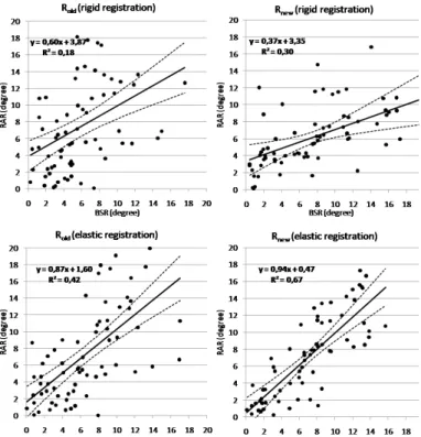
For the correlations between RAR and BSR, we first analyzed the correlation for each thoracic level independently (TABLE II). The two measurements are significantly correlated for the ribs of levels T6 to T11 when taking the RAR from Rnew. However, for T5, the small number of
reconstructions at this level (N=2) do not allow for a correlation analysis. For T12, no significant correlation was found, probably because the rib reconstructions are less accurate at that level, since the T12 ribs are barely visible in both radiographs.
If we now consider all the reconstructions between T5 and T11, we note, in the elastic registration case, a Pearson Fig. 7 - Number of reconstructed rib pairs per thoracic level and per patient.
Each level of the histogram corresponds to a patient.
Fig. 8 - Comparison of the reconstructed ribs Rnew (black) and Rold (gray), for a typical patient, in the frontal plane (a), the sagittal plane (b) and the axial plane (c).
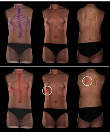
Fig. 9 – Surface topography and rib cage reconstruction of a patient after elastic registration: above, the new reconstructions in blue; below, the old reconstructions in red. The transparency views (on the left) illustrate the registered spine, rib cage and surface topography. The opaque views (in the middle and on the right) represent respectively the anterior and posterior views of the trunk. It can be seen that for the old reconstructions, 2 ribs in the anterior view and 1 rib in the posterior view (circled in white) protrude from the trunk surface.
coefficient of 0.64 when considering Rold, compared to 0.82
when considering Rnew. These values are both statistically
significant (p<0.01). As for the coefficients of determination, they show that, in the case of Rold, 42% of the BSR is
explained by the RAR, whereas in the case of Rnew, 67% of the
BSR is explained by the RAR. The data dispersion around the trend line is 4.28° for Rold and 2.78° for Rnew. The plots of
Fig.11 present the correlations obtained for each set of reconstructed ribs. The linear regression method gives the trend lines equations relating the internal and external rib hump. In the rigid registration case, the correlations for both reconstructions groups (Rnew and Rold) are weaker, with
Pearson coefficients of 0.42 for the Rold and 0.55 for the Rnew.
V. DISCUSSION
A personalized 3D geometric model of the rib cage is essential: firstly, for researchers, to investigate scoliosis pathogenesis as well as the relationships between the spinal and rib cage deformities, and to incorporate the rib cage in a biomechanical model of the trunk used mainly to simulate treatments. Secondly, for clinicians, a 3D reconstruction of the rib cage would constitute a useful evaluation tool, given the fact that ribs axial rotation cannot be quantified in 2D radiographs. Furthermore, in several cases, the rib hump persists after surgical treatment of scoliosis and a thoracoplasty – itself a complex procedure – must sometimes be undertaken. For this reason, a complete biomechanical model, including both the spine and rib cage and capable of simulating different surgery strategies, would be valuable for treatment planning and consequently for achieving better correction of the deformities. Finally, for patients, mainly for those who present a significant rib hump, a better correction of this deformity would enhance their treatment satisfaction and their quality of life.
The method proposed in [29] for the 3D reconstruction of the rib cage relies on two frontal radiographs, PA and PA20. The latter is not a standard view and thus complicates the acquisition protocol. Moreover, it increases patient’s exposure to ionizing radiations, since, for the reconstruction of both the ribcage and the spine, three radiographs are required (PA, PA20 and LAT). On the contrary, we proposed in this paper a method for the 3D reconstruction of scoliotic ribs that relies on the two standard radiographs, PA and LAT, which are also used for the 3D reconstruction of the spine. Consequently, it
does not expose patients to additional radiation dose.
In addition, the method proposed in [29] makes the assumption that the two splines described by the 11 points manually identified on the PA and PA20 projection of the same rib, correspond to the projections of the same 3D rib midline. Due to the manual intervention, this may not be true. Thus, an erroneous matching of the midline in both radiographs leads to considerable errors in the 3D reconstruction process. Our method is using the epipolar geometry to perform an automatic matching of the 3 points manually identified in the LAT X-ray to their corresponding points in the PA which avoid 3D reconstruction errors due to manual matching. Moreover, on the LAT, no rib midline is imposed at the starting point; it is actually inferred by the rib refinement step.
The overall evaluation study has shown that, an elastic registration of the surface of the trunk with the reconstructed ribs improves the results over a rigid registration. In fact, considering either the Rold or Rnew reconstructions, there are
fewer protruding ribs and the correlation between the RAR and BSR is notably increased. This is explained by the fact that the radiographic and topographic acquisitions are not simultaneous and the patient does not retain the same posture. Thus, for future work involving both the trunk surface and the 3D reconstructions of the spine and rib cage, we recommend the use of an elastic registration method.
The visual comparison between Rold and Rnew has shown
that the main differences are located in the sagittal plane, i.e. in the depth dimension with respect to the PA view. Indeed, as was already noted in [46], the variability of the anatomical landmarks reconstructed with the method in [29] is greatest in the sagittal plane. This is due to the low disparity between the PA and PA20 projections and the initial error of matching. In fact, this low disparity makes the 3D reconstruction very sensitive to digitization errors. These differences are much more notable after merging the surface topography with the rib cage reconstructions. The number of protruding rib midlines is considerably lower when considering Rnew.
As for the correlation between the RAR and BSR indices, we notice that the correlation is statistically significant (p<0.05) for the two sets of reconstructions. However, in the case of Rnew, the correlation is stronger and the data dispersion
around the linear model is much lower, as the widths of the confidence intervals illustrated in Fig. 11, especially when TABLE I - NUMBER AND LENGTH OF PROTRUSIONS ALONG EACH PORTION OF THE RIBS
Rold Rnew
Rigid registration Elastic registration Rigid registration Elastic registration
N=164 n l n l n l n l P1 3 16 2 12 0 0 0 0 P2 11 184 8 136 0 0 0 0 P3 5 74 1 22 1 2 1 12 P4 11 122 4 42 3 36 0 0 Total 22 396 12 212 3 38 1 12
(N) Total number of reconstructed ribs (n) number of protruding ribs
considering an elastic registration. This allows us to confirm that, when compared to measurements on the external surface of the trunk the ribs reconstructed by the proposed method provide a better evaluation of the rib hump than the former reconstruction method.
The overall comparative results demonstrate that the three dimensional configuration of the reconstructed ribs obtained using the method proposed in this article are more consistent with the surface topography of the trunk than the reconstructions previously obtained by the method proposed in [29]. Furthermore, the strong correlation between the new RAR and BSR values suggests a reevaluation of the relationship between the internal and external scoliotic deformities. In fact, previous studies [47, 48] have attempted to model the relations between the trunk surface deformity and the spinal deformity, considering the Cobb angle as the sole indicator of the internal deformity. No strong correlation was demonstrated in those studies. However, since the spinal deformity propagates to the trunk surface through the rib cage, it may be more relevant to incorporate the rib cage in this kind of study.
The method proposed in this article succeeded in reconstructing all the ribs that are entirely visible on the LAT view, ranging mainly between T6 and T12. The superposition of the ribs with other bony structures such as the shoulders and arms reduces the visibility of the upper ribs, partially or over their whole length. The number of reconstructions per patient depends on various factors, like the position of the arms during the acquisition. Indeed, the two patients for whom the ribs at level T5 were successfully reconstructed had their upper arms raised at an angle of more than 90° from the rest position. Even though the X-ray acquisition protocol suggests a 45° angle, some protocol deviations can occur occasionally. Fortunately, those cases happened to be favorable to our study. Thus, for the purpose of rib cage 3D reconstruction, we recommend that during the X-ray acquisitions patients have their upper arms raised at an angle of 90°. However, precaution should be taken to avoid involuntary bending of the spine. Meanwhile, the radiographic parameters also affect the visibility of the ribs; however, their values are limited by the risks related to the radiation dose. Better image quality, e.g. using the EOS system [49], could increase the visibility of the
upper ribs in the LAT, and thus allow the reconstruction of more levels. Nonetheless, the rib pairs of levels T5 to T12 are the most susceptible to present a significant rib hump and are thus the most relevant for the evaluation of rib cage deformities.
For ends of comparison with the method previously proposed in the literature, we had to select AIS patients for whom a PA20 X-ray was also acquired. At our clinic, relatively few patients met this specific criterion, considering the fact that this non standard radiograph was required only for a specific research study aiming at evaluating a computer-assisted tool for the design and adjustment of braces [50]. Among this cohort of 24 patients, the data of five patients were excluded from the study because their LAT image was incomplete due to poor positioning during the X-ray acquisition. Then, from this pool of patients, we considered the data of 13 patients whose radiographs were of satisfactory quality. Surgical candidates were not intentionally excluded from this study, but the patients meeting our inclusion criteria were, according to the protocol of [50], candidate for brace treatment. This explains why the mean Cobb angle observed in our cohort is only 36°. Nevertheless, in future works, we aim at using this 3D reconstruction method for surgical candidates, to assess the effects of surgery.
As the clinical study is retrospective, we had to use the data as it is and find a way to determine the left and right ribs from X-rays content. The method proposed in this paper for the 3D reconstruction of scoliotic ribs relies on the localization of the rib hump in order to distinguish the right and left ribs in the LAT film. However, for prospective studies, we suggest the Fig. 10 - Standard deviation and mean distances between the ribs and the
surface topography along the head (P1), posterior (P2), lateral (P3) and anterior (P4) portions of the ribs, and over their whole length (Total). The statistically significant differences (p<0.05) between the Rold and Rnew are marked by asterisks.
Fig. 11 - Correlation between the back surface rotation (BSR) and the ribs axial rotation (RAR). Each point represents a pair of ribs. For each plot, the solid line represents the trend line, and the dotted lines represent the 95% confidence intervals.
use of two different set of radio-opaque markers varying in shape that could be placed on the right or on the left sides of the back according to their shape. This would bypass the problem related to the potential absence of rib hump. Those markers could serve at the same time as additional landmarks for the registration of the trunk surface with the 3D reconstruction of the spine and rib cage.
Even though the used of an elastic registration reduced the number of protruding ribs, one rib among the 164 new reconstructions still protrudes from the external surface, specifically in its lateral portion. This can be attributed first to the accuracy of the surface topography in the lateral regions of the trunk which is weaker than in the frontal and posterior regions, this being essentially due to the spatial configuration of the four InSpeck digitizers and the arms position during the acquisition. Moreover, as mentioned in section III.C above, the elastic registration between the surface topography and the reconstruction of the bony structures is based on a sparse set of markers. In that small marker set, only one or two are placed on the lateral regions of the trunk, which contributes to a less accurate registration in those regions. For better results, we recommend using additional markers on these critical portions of the trunk.
It should be mentioned that for a rib not to protrude from the surface of the trunk is a necessary but not a sufficient condition for the validity of the reconstruction. Thus, it is more rigorous to compare the distances between the ribs and the surface of the trunk to reference values. Anatomically speaking, the local distance d calculated between the rib midline and the surface topography spans half the cross-section of the rib, combined with the thicknesses of the muscles, the soft tissues, the adipose tissue and the skin. No other similar work has been found in the literature with which to compare this particular result. MRI acquisitions could potentially be used to validate our results for these distances. To avoid compressing the soft tissues of the back, the MRI volume should be acquired in the upright position. However, to our knowledge, the actual MRI systems that allow this are not powerful enough to provide a sufficient resolution for this kind of study.
In clinic, a reasonable time for obtaining the spine and ribcage in 3D would be about 30 to 40 minutes after the X-ray acquisition. Meanwhile, other clinical exams are performed
such as the acquisition of the trunk topography of the patient. The technique used previously at our hospital for the 3D reconstruction of the rib cage, required about 2 hours, since it relies on the manual identification of 11 points per ribs in both PA and PA-20 radiographs, hence a total of 22 points per rib. In fact, the digitization of the ribs in the X-rays constitutes the most time-consuming step. In the present study, only 3 points per rib are manually identified in the LAT and the same 11 points per rib in the PA were used only in order to adequately compare the two reconstruction methods. Thus, the total number of primitives per rib in our method is 14. Furthermore, a semi-automatic detection of rib contours [51] in the PA (which requires the identification of 4 points per rib), combined with an automatic extraction of the rib midlines, could reduce the manual intervention to only 7 points per rib (3 in the LAT and 4 in the PA). This would, first, increase the repeatability of ribs identification step and, second, it would reduce the processing time by about two thirds (40 minutes approximately), making our method more suitable in a clinical setting.
VI. CONCLUSION
We have proposed in this article a new method for the 3D reconstruction of scoliotic rib midlines, based on two standard radiographs in the frontal and lateral planes, commonly acquired in the clinical setting at Sainte-Justine Hospital, Montreal, Canada. Compared to the reconstruction method previously used at our clinic, patients’ exposure to ionizing radiation is reduced. The high disparity between the two X-rays gives more representative reconstructions than those obtained with the current method. Although only the inferior half of the rib cage is reconstructed with the proposed method, it is this portion that is of greatest interest to clinicians because it is the most deformed part of the rib cage in scoliotic patients.
Moreover, we have presented an original evaluation method using the surface topography as a reference modality. The reconstructions obtained using our technique yield a better correlation between the ribs axial rotation and the back surface rotation. This is a promising finding for the study of the relationships between the spinal, rib cage and trunk surface deformities in adolescent idiopathic scoliosis. Furthermore,
TABLE II - RAR-BSR CORRELATION AT EACH THORACIC LEVEL
Rold Rnew
Rigid registration Elastic registration Rigid registration Elastic registration
Ribs level N R R R R T5 2 1,00 1,00 1,00 1,00 T6 6 0,23 0,49 0,86 * 1,00 ** T7 10 0,68 * 0,71 * 0,91 ** 0,90 ** T8 12 0,37 0,70 * 0,70 * 0,81 ** T9 13 0,35 0,64 * 0,55 * 0,75 ** T10 13 -0,02 0,40 0,42 0,70 ** T11 13 0,69 ** 0,72 ** 0,21 0,73 ** T12 13 0,43 -0,06 -0,33 -0,15
(*) significant correlation (p<0,05) (R) Pearson correlation coefficient (**) significant correlation (p<0,01) (N) Number of reconstructed ribs pairs
this new reconstruction technique has the potential to help clinicians to better understand the nature of the rib hump and thereby to incorporate the rib cage more effectively in the treatment of scoliosis.
ACKNOWLEDGMENT
The authors would like to thanks P. Debanné for revising this manuscript and C. Bellefleur for his technical contribution.
REFERENCES
[1] E. J. Rogala, D. S. Drummond, and J. Gurr, "Scoliosis: incidence and natural history. A prospective epidemiological study," J Bone Joint Surg Am, vol. 60, pp. 173-6, Mar 1978.
[2] J. R. Cobb, "Outline for the study of scoliosis," Am Acad Orthop Surg
Instruct Lect, vol. 5, pp. 261-275, 1948.
[3] H. Graf, J. Hecquet, and J. Dubousset, "[3-dimensional approach to spinal deformities. Application to the study of the prognosis of pediatric scoliosis]," Rev Chir Orthop Reparatrice Appar Mot, vol. 69, pp. 407-16, 1983.
[4] R. Perdriolle, La scoliose, son étude tridimensionnelle. Paris: Maloine SA, 1979.
[5] R. Roaf, "Rotation movements of the spine with special reference to scoliosis," J Bone Joint Surg Br, vol. 40-B, pp. 312-32, May 1958. [6] J. Dansereau, A. Beauchamp, J. De Guise, and H. Labelle,
"Three-dimensional reconstruction of the spine and the rib cage from stereoradiographic and imaging techniques," in 16th conference of the
Canadian Society of Mechanical Engineering, Toronto, Canada, 1990, pp. 61-64.
[7] F. Cheriet, C. Laporte, S. Kadoury, H. Labelle, and J. Dansereau, "A novel system for thE 3-D reconstruction of the human spine and rib cage from biplanar X-ray images," IEEE Trans Biomed Eng, vol. 54, pp. 1356-8, Jul 2007.
[8] S. Kadoury, F. Cheriet, C. Laporte, and H. Labelle, "A versatile 3D reconstruction system of the spine and pelvis for clinical assessment of spinal deformities," Med Biol Eng Comput, vol. 45, pp. 591-602, Jun 2007.
[9] S. Delorme, Y. Petit, J. A. de Guise, H. Labelle, C. E. Aubin, and J. Dansereau, "Assessment of the 3-d reconstruction and high-resolution geometrical modeling of the human skeletal trunk from 2-D radiographic images," IEEE Trans Biomed Eng, vol. 50, pp. 989-98, Aug 2003. [10] L. T. Cook, A. A. DeSmet, M. A. Tarlton, and S. L. Fritz, "Assessment of
scoliosis using three-dimensional analysis," IEEE Transactions on
Biomedical Engineering, vol. BME-28, pp. 366-371, 1981.
[11] D. Mitton, C. Landry, S. Véron, W. Skalli, F. Lavaste, and J. De Guise, "3D reconstruction method from biplanar radiography using non-stereocorresponding points and elastic deformable meshes," Medical and
Biological Engineering and Computing, vol. 38, pp. 133-139, 2000. [12] V. Pomero, D. Mitton, S. Laporte, J. A. de Guise, and W. Skalli, "Fast
accurate stereoradiographic 3D-reconstruction of the spine using a combined geometric and statistic model," Clin Biomech (Bristol, Avon), vol. 19, pp. 240-7, Mar 2004.
[13] S. Benameur, M. Mignotte, H. Labelle, and J. A. De Guise, "A hierarchical statistical modeling approach for the unsupervised 3-D biplanar reconstruction of the scoliotic spine," IEEE Trans Biomed Eng, vol. 52, pp. 2041-57, Dec 2005.
[14] R. Dumas, B. Blanchard, R. Carlier, C. G. de Loubresse, J. C. Le Huec, C. Marty, M. Moinard, and J. M. Vital, "A semi-automated method using interpolation and optimisation for the 3D reconstruction of the spine from bi-planar radiography: a precision and accuracy study," Med Biol Eng
Comput, vol. 46, pp. 85-92, Jan 2008.
[15] J. Boisvert, F. Cheriet, X. Pennec, H. Labelle, and N. Ayache, "Articulated spine models for 3-D reconstruction from partial radiographic data," IEEE Trans Biomed Eng, vol. 55, pp. 2565-74, Nov 2008.
[16] S. Kadoury, F. Cheriet, J. Dansereau, and H. Labelle, "Three-dimensional reconstruction of the scoliotic spine and pelvis from uncalibrated biplanar x-ray images," J Spinal Disord Tech, vol. 20, pp. 160-7, Apr 2007. [17] I. A. Stokes, "Axial rotation component of thoracic scoliosis," J Orthop
Res, vol. 7, pp. 702-8, 1989.
[18] G. Erkula, P. D. Sponseller, and A. E. Kiter, "Rib deformity in scoliosis,"
Eur Spine J, vol. 12, pp. 281-7, Jun 2003.
[19] T. Thulbourne and R. Gillespie, "The rib hump in idiopathic scoliosis. Measurement, analysis and response to treatment," J Bone Joint Surg Br, vol. 58, pp. 64-71, Feb 1976.
[20] W. P. Bunnell, "Outcome of spinal screening," Spine, vol. 18, pp. 1572-80, Sep 15 1993.
[21] M. Asher, S. M. Lai, D. Burton, and B. Manna, "The influence of spine and trunk deformity on preoperative idiopathic scoliosis patients' health-related quality of life questionnaire responses," Spine, vol. 29, pp. 861-8, Apr 15 2004.
[22] J. Jaremko, S. Delorme, J. Dansereau, H. Labelle, J. Ronsky, P. Poncet, J. Harder, R. Dewar, and R. F. Zernicke, "Use of Neural Networks to Correlate Spine and Rib Deformity in Scoliosis," Comput Methods
Biomech Biomed Engin, vol. 3, pp. 203-213, 2000.
[23] R. F. Closkey and A. B. Schultz, "Rib cage deformities in scoliosis: spine morphology, rib cage stiffness, and tomography imaging," J Orthop Res, vol. 11, pp. 730-7, Sep 1993.
[24] M. Hawes, "Impact of spine surgery on signs and symptoms of spinal deformity," Pediatr Rehabil, vol. 9, pp. 318-39, Oct-Dec 2006.
[25] T. G. Lowe, M. Edgar, J. Y. Margulies, N. H. Miller, V. J. Raso, K. A. Reinker, and C. H. Rivard, "Etiology of idiopathic scoliosis: current trends in research," J Bone Joint Surg Am, vol. 82-A, pp. 1157-68, Aug 2000.
[26] G. P. Pal, "Mechanism of production of scoliosis. A hypothesis," Spine, vol. 16, pp. 288-92, Mar 1991.
[27] J. A. Sevastik, S. Aaro, and H. Normelli, "Scoliosis. Experimental and clinical studies," Clin Orthop Relat Res, pp. 27-34, Dec 1984.
[28] T. B. Grivas, E. S. Vasiliadis, C. Mihas, and O. Savvidou, "The effect of growth on the correlation between the spinal and rib cage deformity: implications on idiopathic scoliosis pathogenesis," Scoliosis, vol. 2, p. 11, 2007.
[29] J. Dansereau and I. A. Stokes, "Measurements of the three-dimensional shape of the rib cage," J Biomech, vol. 21, pp. 893-901, 1988.
[30] E. Marcil, "Incorporation du deplacement du patient dans la reconstruction radiographique tridimensionnelle de la cage thoracique et du rachis humain," Ecole Polytechnique, Montreal (Canada), 1996. [31] C. E. Aubin, J. Dansereau, F. Parent, H. Labelle, and J. A. de Guise,
"Morphometric evaluations of personalised 3D reconstructions and geometric models of the human spine," Med Biol Eng Comput, vol. 35, pp. 611-8, Nov 1997.
[32] S. Mouren, "Reconstruction a trois dimensions biplanaire de cages thoraciques scoliotiques a l'aide de modeles deformables de cotes," Ecole Polytechnique, Montreal (Canada), 2003.
[33] S. Benameur, M. Mignotte, F. Destrempes, and J. A. De Guise, "Three-dimensional biplanar reconstruction of scoliotic rib cage using the estimation of a mixture of probabilistic prior models," IEEE Trans
Biomed Eng, vol. 52, pp. 1713-28, Oct 2005.
[34] S. Laporte, W. Skalli, B. Aubert, S. Bertrand, and D. Mitton, "3D reconstruction of the rib cage from biplanar X-rays," Proceedings of the
18th International Congress on Computer Assisted Radiology ans Surgery, 2004.
[35] D. Mitton, K. Zhao, S. Bertrand, C. Zhao, S. Laporte, C. Yang, K. N. An, and W. Skalli, "3D reconstruction of the ribs from lateral and frontal X-rays in comparison to 3D CT-scan reconstruction," J Biomech, vol. 41, pp. 706-10, 2008.
[36] C. Bellefleur, J. Dansereau, A. Koller, and H. Labelle, "Evaluation of the efficiency of patient stabilization devices for 3D X-ray reconstruction of the spine and rib cage," Stud Health Technol Inform, vol. 88, pp. 127-31, 2002.
[37] E. Vallieres, "The costovertebral angle," Thorac Surg Clin, vol. 17, pp. 503-10, Nov 2007.
[38] F. Poulin, "Reconstruction et modélisation du col costal à l'aide de radiographies numériques," École Polytechnique, Montréal (Canada), 1996.
[39] L. G. Lenke, R. R. Betz, J. Harms, K. H. Bridwell, D. H. Clements, T. G. Lowe, and K. Blanke, "Adolescent idiopathic scoliosis: a new classification to determine extent of spinal arthrodesis," J Bone Joint Surg
Am, vol. 83-A, pp. 1169-81, Aug 2001.
[40] G. M. Graeber and M. Nazim, "The anatomy of the ribs and the sternum and their relationship to chest wall structure and function," Thorac Surg
Clin, vol. 17, pp. 473-89, vi, Nov 2007.
[41] S. B. Roberts and P. H. Chen, "Global geometric characteristics of typical human ribs," J Biomech, vol. 5, pp. 191-201, Mar 1972.
[42] V. Pazos, F. Cheriet, H. Labelle, and J. Dansereau, "3D reconstruction and analysis of the whole trunk surface for non-invasive follow-up of scoliotic deformities," Stud Health Technol Inform, vol. 91, pp. 296-9, 2002.
[43] V. Pazos, F. Cheriet, J. Danserau, J. Ronsky, R. F. Zernicke, and H. Labelle, "Reliability of trunk shape measurements based on 3-D surface reconstructions," Eur Spine J, vol. 16, pp. 1882-91, Nov 2007.
[44] V. Pazos, F. Cheriet, L. Song, H. Labelle, and J. Dansereau, "Accuracy assessment of human trunk surface 3D reconstructions from an optical digitising system," Med Biol Eng Comput, vol. 43, pp. 11-5, Jan 2005. [45] K. Rohr, H. S. Stiehl, R. Sprengel, T. M. Buzug, J. Weese, and M. H.
Kuhn, "Landmark-based elastic registration using approximating thin-plate splines," IEEE Transactions on Medical Imaging, vol. 20, pp. 526-534, 2001.
[46] H. Labelle, J. Dansereau, C. Bellefleur, and J. C. Jequier, "Variability of geometric measurements from three-dimensional reconstructions of scoliotic spines and rib cages," Eur Spine J, vol. 4, pp. 88-94, 1995. [47] J. L. Jaremko, P. Poncet, J. Ronsky, J. Harder, J. Dansereau, H. Labelle,
and R. F. Zernicke, "Genetic algorithm-neural network estimation of cobb angle from torso asymmetry in scoliosis," J Biomech Eng, vol. 124, pp. 496-503, Oct 2002.
[48] C. J. Goldberg, M. Kaliszer, D. P. Moore, E. E. Fogarty, and F. E. Dowling, "Surface topography, Cobb angles, and cosmetic change in scoliosis," Spine, vol. 26, pp. E55-63, Feb 15 2001.
[49] J. Dubousset, G. Charpak, I. Dorion, W. Skalli, F. Lavaste, J. Deguise, G. Kalifa, and S. Ferey, "[A new 2D and 3D imaging approach to musculoskeletal physiology and pathology with low-dose radiation and the standing position: the EOS system]," Bull Acad Natl Med, vol. 189, pp. 287-97; discussion 297-300, Feb 2005.
[50] H. Labelle, C. Bellefleur, J. Joncas, C. E. Aubin, and F. Cheriet, "Preliminary evaluation of a computer-assisted tool for the design and adjustment of braces in idiopathic scoliosis: a prospective and randomized study," Spine, vol. 32, pp. 835-43, Apr 15 2007.
[51] F. Plourde, F. Cheriet, and J. Dansereau, "Semi-automatic detection of scoliotic rib borders using chest radiographs," Stud Health Technol
Inform, vol. 123, pp. 533-7, 2006.
Lama Seoud was born in Beirut, Lebanon,
in 1983. She received her biomedical engineering degree at École Supérieure d’Ingénieurs de Beyrouth, Lebanon, in 2001. She is currently working toward the Ph.D. degree in biomedical engineering at École Polytechnique de Montréal, Québec, Canada. Her research interests are in 3D reconstruction techniques, medical imaging and pattern recognition.
Farida Cheriet received the B.Sc. degree
in computer science from the University USTHB, Algiers, in 1984, the D.E.A. degree in the field of languages, algorithms and programming from the University of Paris VI, France, in 1986, and the Ph.D. degree in computer science from the University of Montreal, QC, Canada, in 1996.
Since 1999, she is with the Department of Computer Engineering, École Polytechnique de Montréal, where she is currently a Full Professor. Her research interests include, three-dimensional (3D) reconstruction of bone structures from x-rays, calibration of X-ray imaging systems, non-invasive 3D modeling of scoliosis deformities, 3D navigation systems for minimally invasive surgery, 3D reconstruction of vascular structures from angiographic images, and 3D motion estimation from spatio-temporal sequences.
Hubert Labelle received the M.D. degree and completed his residency in orthopedics at University of Montréal, Montréal, QC, Canada. He completed a two-year fellowship in pediatric orthopedics at Sainte-Justine Hospital, Montréal, Rancho Los Amigos Hospital, Downey, CA, and the A.I. Du Pont Institute, Wilmington, DE. Since 1982, he has held an appointed in the Department of Surgery at University of Montréal and at Ste-Justine Hospital where he is currently a Professor of surgery and Titular of the Motion Sciences Research Chair of Sainte-Justine Hospital and the University of Montreal.
His clinical work is focused on the evaluation and treatment of scoliotic deformities in children and adolescents. He is head of the musculoskeletal research group at Sainte-Justine Hospital Research Center and Director of the Three-Dimensional Scoliosis Laboratory. His research interests include the 3D evaluation and treatment of scoliotic deformities, with a particular emphasis on computer assisted surgery, 3D design and evaluation of braces for the treatment of idiopathic scoliosis, and 3D evaluation and simulation of surgery for scoliotic deformities.
Jean Dansereau received the B.Eng. and
M.Sc. A. degrees in mechanical engineering from École Polytechnique de Montréal, Québec, Canada, in 1981 and 1983 respectively. He obtained the Ph.D. degree in mechanical engineering (biomechanics) from the University of Vermont, Burlington, in 1987.
Since 1986, he is professor at the Department of Mechanical Engineering and at the Biomedical Engineering Institute of École Polytechnique of Montreal. Between 1996 and 2001, he was responsible of the NSERC Industrial Research Chair on Wheelchair Seating Aids at the same institution. He is presently the Associate Dean of Studies and Director of Graduate Studies at École Polytechnique of Montreal. His current interests are spinal biomechanics, 3-D radiographic reconstruction and computer modelling of scoliotic spines and ribcages as well as rehabilitation engineering.