HAL Id: tel-02418752
https://tel.archives-ouvertes.fr/tel-02418752
Submitted on 19 Dec 2019HAL is a multi-disciplinary open access archive for the deposit and dissemination of sci-entific research documents, whether they are pub-lished or not. The documents may come from
L’archive ouverte pluridisciplinaire HAL, est destinée au dépôt et à la diffusion de documents scientifiques de niveau recherche, publiés ou non, émanant des établissements d’enseignement et de
understanding and optimizing the boot operation
Thuy Linh Nguyen
To cite this version:
Thuy Linh Nguyen. Fast delivery of virtual machines and containers : understanding and optimizing the boot operation. Distributed, Parallel, and Cluster Computing [cs.DC]. Ecole nationale supérieure Mines-Télécom Atlantique, 2019. English. �NNT : 2019IMTA0147�. �tel-02418752�
T
HESE DE DOCTORAT DE
L
’É
COLEN
ATIONALES
UPERIEUREM
INES-T
ELECOMA
TLANTIQUEB
RETAGNEP
AYS DE LAL
OIRE-
IMT
A
TLANTIQUECOMUE UNIVERSITE BRETAGNE LOIRE
ECOLE DOCTORALE N°601
Mathématiques et Sciences et Technologies de l'Information et de la Communication
Spécialité : Informatique et applications
Fast delivery of Virtual Machines and Containers: Understanding and
optimizing the boot operation
Thèse présentée et soutenue à Nantes, le 24 Septembre 2019 Unité de recherche : Inria Rennes Bretagne Atlantique
Thèse N° : 2019IMTA0147 Par
Thuy Linh NGUYEN
Rapporteurs avant soutenance :
Maria S. PEREZ Professeure, Universidad Politecnica de Madrid, Espagne Daniel HAGIMONT Professeur, INPT/ENSEEIHT, Toulouse, France
Composition du Jury :
Président : Mario SUDHOLT Professeur, IMT Atlantique, France
Rapporteur : Maria S. PEREZ Professeure, Universidad Politecnica de Madrid, Espagne Rapporteur : Daniel HAGIMONT Professeur, INPT/ENSEEIHT, Toulouse, France
Examinateurs : Ramon NOU Chercheur, Barcelona Supercomputing Center, Espagne Dir. de thèse : Adrien LEBRE Professeur, IMT Atlantique, France
Acknowledgements
The PhD journey is not a long journey but definitely a memorable time in my life. I see myself growing both professionally and personally. I would like to express appreciation to many people for all their advice, support, and inspiration for my progress.
First of all, I would like to express my gratitude to my thesis supervisor Adrien Lebre. I have enjoyed working with him very much and to me, that was my luck to have a very nice supervisor for my PhD life. Not only he has provided me with professional guidance and strict feedback on my research work, but he has also been an inspiration for me. He always brought out the positive aspect in difficult time during my PhD. This was very important to me and it helped me to go through the hard time. I also learned from him how to write scientific articles and how to present my work to others in the most efficient way.
I was having a great opportunity to have my internship at Barcelona Supercomputing Center. I am thankful for all the discussion and efforts that my advisor, Ramon Nou, spent on me. He gave me a lot of encouragement when I got stuck in my research.
I would like to especially thank my thesis committee members for their valuable time and feedback on my manuscript.
I am so grateful for my time at INRIA, I had a wonderful time there. The institute provided me with the best working environment I could ever think of. Thanks to Anne-Claire, she has always given me the best guidance to the administration of INRIA and my doctoral school at IMT Atlantique.
Thank you to all my colleagues at STACK team. We had many interesting discus-sions either scientific-related matters or social-related ones at lunchtime or over coffee time. Thank you for the gaming nights that you guys tried so hard to persuade me to join the path of playing games, thank you for the hangout time after work in the hot summer days. These things made my PhD life much more enjoyable.
I am also proud and really appreciate the opportunity that I received from taking part in the BigStorage project. The project brought PhD candidates working in institutes and universities around Europe together. I met and worked with other PhD candidates and supervisors to exchange ideas, experiences and culture clashes. With many training programs and meetings, I had opportunities to improve my skills and collaborate in this small research community.
exciting new experiences. It was a big motivation and full of energy as well as stress and challenging at the same time.
Finally, I cannot thank enough my family. Without their support, I cannot imagine how I can walk through all the ups and downs in my journey. They are always, and will always support and take care of me.
Contents
List of Tables v
List of Figures vii
I
Introduction
1
II
Utility Computing and Provisioning Challenges
7
1 Utility Computing 9
1.1 Utility Computing: from Mainframes to Cloud Computing Solutions . 10
1.2 Virtualization System Technologies: A Key Element . . . 12
1.3 Hardware Virtualization . . . 13
1.3.1 Types of Hardware Virtualization . . . 13
1.3.2 Discussion . . . 15
1.3.3 Hypervisor . . . 16
1.3.4 Virtualized Interfaces . . . 17
1.4 OS-level Virtualization (or Containerization) . . . 19
1.5 Virtualization Overhead . . . 20
1.5.1 CPU Overhead . . . 21
1.5.2 Memory Overhead . . . 22
1.5.3 Network Overhead . . . 22
1.5.4 Disk I/O Overhead . . . 22
1.6 Summary . . . 23
2 IaaS Toolkits: Understanding a VM/Container Provisioning Process 25 2.1 Overview . . . 26
2.2 Step 2: VM/Container Image Retrieval . . . 26
2.2.1 Retrieving Process . . . 26
2.2.2 Retrieving Process Issues and Solutions . . . 27
2.3.1 Boot Process . . . 30
2.3.2 Boot Process Issues and Solutions . . . 31
2.4 Summary . . . 33
3 Technical background on QEMU-KVM VM and Docker Container 35 3.1 QEMU-KVM Virtual Machine . . . 36
3.1.1 QEMU-KVM Work Flow . . . 36
3.1.2 VM Disk Types . . . 37
3.1.3 Amount of Manipulated Data in a VM Boot Process . . . 37
3.2 Docker Container . . . 39
3.2.1 Docker Container Work Flow . . . 39
3.2.2 Docker Image . . . 40
3.2.3 Amount of Manipulated Data of a Docker Boot Process . . . 41
3.3 Summary . . . 41
III
Contribution: Understanding and Improving VM/Container
Boot Duration
43
4 Understanding VM/Container Boot Time and Performance Penalties 45 4.1 Experiments Setup . . . 464.1.1 Infrastructure . . . 46
4.1.2 VM and Container Configurations . . . 46
4.1.3 Benchmark Tools . . . 47
4.1.4 Boot Time Definition . . . 48
4.1.5 A Software Defined Experiment . . . 48
4.2 Boot Time In No-Workload Environment . . . 50
4.2.1 VM Boot Time . . . 50
4.2.2 Docker Boot Time . . . 52
4.2.3 Nested Docker Boot Time . . . 52
4.2.4 Discussion . . . 53
4.3 Boot Time Under Workloads Contention . . . 54
4.3.1 Memory Impact . . . 54
4.3.2 CPU Impact . . . 55
4.3.3 Network Impact . . . 55
4.3.4 I/O Disk Impact . . . 56
4.3.5 Discussion . . . 57
4.4 Preliminary Studies . . . 58
4.4.1 Prefetching initrd and kernel files . . . . 58
4.4.2 Prefetching Mandatory Data . . . 58
Contents v
5 YOLO: Speed Up VMs and Containers Boot Time 63
5.1 YOLO Design and Implementation . . . 64
5.1.1 Boot Image . . . 64
5.1.2 yolofs . . . 65
5.2 Experimenting Protocol . . . 66
5.2.1 Experimental Conditions . . . 68
5.2.2 Boot Time Policies . . . 68
5.3 VM Boot Time Evaluation . . . 69
5.3.1 Deployment multiples VMs . . . 70
5.3.2 Booting One VM Under High Consolidation Ratio . . . 72
5.4 Docker Container Boot Time Evaluation . . . 74
5.4.1 Booting Multiple Distinct Containers Simultaneously . . . 75
5.4.2 Booting One Docker Container Under I/O Contention . . . . 75
5.5 yolofs Overhead . . . . 76
5.6 Integrating YOLO into cloud systems . . . . 77
5.7 Summary . . . 78
IV
Conclusions and Perspectives
79
6 Summary of Contributions 81 7 Directions for Future Research 85 7.1 Improving YOLO . . . 857.2 YOLO in a FaaS model . . . . 87
7.3 An allocation strategy with boot time awareness . . . 88
A Appendix A: VM Boot Time Model 89 A.1 Motivation . . . 89
A.2 VM Boot Time Model . . . 90
A.3 Model Evaluation . . . 92
A.4 Conclusion . . . 94
Résumé en Français 94
List of Tables
2.1 Summary methodologies to transferring images . . . 27 3.1 The amount of read data during a docker boot process . . . 41 5.1 The statistics of 900+ Google Cloud VMIs and their boot images. We
group the VMIs into image families and calculate the boot images for each image family. . . 65 5.2 Time (second) to perform sequential and random read access on a
backing file of VMs which are booted by normal boot and YOLO on three storage devices. . . 76 5.3 The number of transactions per second (tps) when running pgbench
inside a VM booted using YOLO and normal way on 3 types of storage devices. . . 76 5.4 Booting VM with OpenStack . . . 77
List of Figures
1.1 Overview of Grid and Cloud computing, updated version of [1] . . . . 11
1.2 Traditional and Virtual Architecture . . . 13
1.3 The binary translation approach to x86 virtualization [2] . . . 14
1.4 The Para-virtualization approach to x86 Virtualization [2] . . . 15
1.5 The hardware assist approach to x86 virtualization [2] . . . 15
1.6 2 types of hypervisors . . . 16
1.7 Virtualization Architecture . . . 19
1.8 CPU Virtualization Overhead [3] . . . 21
1.9 Virtualization Overhead - I/O Disk (reads/writes) [3] . . . 23
2.1 VM boot process . . . 30
2.2 Container boot process . . . 30
3.1 QEMU/KVM with virtio work flow . . . 36
3.2 Two types of VM disk . . . 37
3.3 The amount of manipulated data during boot operations (reads/writes) 38 3.4 The number of I/O requests during boot operations (reads/writes) . . . 39
3.5 Container work flow . . . 39
3.6 Docker union file system: overlayfs [4] . . . . 40
4.1 Engine Architecture . . . 49
4.2 Boot time of VMs with different installations on three storage devices 50 4.3 Boot time of multiple VMs, Dockers and Nested Dockers on 3 storage devices . . . 52
4.4 I/O usage during boot process of multiple machines . . . . 53
4.5 Boot time of 1 VM, Docker and Nested Docker on three storage devices under memory contention . . . 54
4.6 Boot time of 1 VM, Docker and Nested Docker on three storage devices under CPU contention . . . 55
4.7 Boot time of 1 VM, Docker and Nested Docker on three storage devices under network contention . . . 56
4.8 Boot time of 1 VM, Docker and Nested Docker on three storage devices under I/O contention . . . 56 4.9 Read accesses during a VM boot process. Each dot corresponds to an
access at a certain period of the boot process and a certain offset. . . . 59 4.10 Time comparison for prefetching the VM boot mandatory data . . . . 59 5.1 yolofs read/write data flow . . . 66 5.2 Four investigated boot policies. Each block represents the time it takes
to finish. Prefetching boot performs prefetching in a parallel fashion to leverage gaps during the booting process of a VMs for faster loading. YOLOloads and serves boot images whenever VMs need to access the mandatory data. . . 68 5.3 Overhead of serving boot’s I/O requests directly from the memory vs. a
dedicated SSD . . . 69 5.4 Time to boot multiple VMs, which share the same VMI (cold
environ-ment: there is no other VMs that are running on the compute node) . . 70 5.5 Time to boot multiple VMs, which have different VMIs (cold
environ-ment: there is no other VMs that are running on the compute node) . . 71 5.6 Boot time of 1 VM (with shared image disk, write through cache mode)
under I/O contention environment . . . 72 5.7 Boot time of 1 VM (with shared image disk, write through cache mode)
under memory usage contention environment . . . 73 5.8 Boot time of different docker containers on different storage devices . 75 5.9 Boot time of one debian docker container under I/O contention . . . . 75 7.1 Overview of a Function as a Service (FaaS) model . . . 87 A.1 The comparison of VM boot time with 4 factors: I/O throughput, CPU
capacity, memory utilization and the mixed factors, on HDD vs SSD. The y-axis shows VM boot time in seconds on a log scale with base 10 91 A.2 The correlation between VM boot time and resources utilization with
two disk creation strategies, on HDD and SSD . . . 92 A.3 Boot time with different resource contentions on HDD . . . 93 A.4 Boot time with different resource contentions on SSD . . . 93
Publications
Virtual Machine Boot Time Model, T. L. Nguyen and A. Lebre. In Proceeding of IEEE Parallel, Distributed and Network-based Processing (PDP), 2017 25th Euromicro International Conference on IEEE, March 2017
Conducting Thousands of Experiments to Analyze VMs, Dockers and Nested Dockers Boot Time, T. L. Nguyen and A. Lebre. Research Report RR-9221, Inria Rennes Bretagne Atlantique, November 2018
YOLO: Speeding up VM Boot Time by reducing I/O operations, T. L. Nguyen and A. Lebre. Research Report RR-9245, Inria Rennes Bretagne Atlantique, January 2019
YOLO: Speeding up VM and Docker Boot Time by reducing I/O operations, T. L. Nguyen, R. Nou and A. Lebre. In Proceeding of 25th Europar conference, August 2019
I
3 In this information era, we witness the emergence of Cloud Computing as the revolutionized force for the IT industry. Taking advantage of the abundant resources combined with the rapid development of web technologies, Cloud Computing has realized the idea of "computing as a utility". Today, users can access different services powered by the cloud literally everywhere from navigating with Google Maps, and watching movies on-demand with Netflix, to having a teleconference with business partners halfway around the world using Skype. All of these services are made possible by having heavy computation handled by the cloud. Moreover, start-ups use the cloud infrastructures to materialize their ideas without the hassle of having to build and manage their own physical infrastructure.
One key technology in the development of Cloud Computing is system virtualiza-tion. System virtualization can be thought of as the abstraction of a physical object. Such abstraction allows the split of physical resources into groups of different sizes in order to share them between different "virtualized environments". This way of sharing resources among different tenants is a critical capability to utilize physical resources effectively on the massive scale of a cloud system. In Cloud Computing, different types of virtualization technologies have been proposed but Virtual Machines (VMs) and Containers are the two most important ones. A VM is the combination of differ-ent physical resources under a layer of abstraction on which users can perform their tasks. Meanwhile, containers introduce a lighter and more efficient approach to the virtualization of the physical resources [5, 6, 7, 8, 9, 10]. Without diving into details for the moment, all these studies presented the same conclusion: the performance of a container-based application is close to that of the bare metal, while there was a significant performance degradation when running the same application in a VM, especially for VM I/O accesses.
Among key operations of a cloud resource management system, the provisioning process is in charge of deploying and starting a VM (or a container as fast as possible). It is composed of three complex stages: (i) after receiving the provisioning order for a machine, a scheduler identifies an appropriate physical node to host the VM/container; (ii) the image for that machine will be transferred from a repository to the designated node; (iii) and finally, the requested VM/container is booted. To solve the resource scheduling problem of the first stage, several approaches have been proposed over the years with different scheduling policies according to the expected objective (energy saving, QoS guarantee, etc.,) and various methodologies in order to reduce as much as possible the computation time [11, 12]. Depending on the properties of the client’s request, the availability of physical resources and the scheduling algorithm criteria, the duration of the scheduling operation can vary. For the image retrieval, i.e., the second stage, most cloud solutions leverage a centralized approach where VM/container images are transferred from a centralized repository to the physical host that will be in charge of hosting the “virtualized environment”. To deal with performance penalties that raises such a centralized approach, several works have focused on improving the
transfer of these images over the network, leveraging techniques such as peer-to-peer image transferring, deduplication or caching method, etc., [13, 14, 15, 16, 17]. The last stage consists of turning on the VM/container itself. It is noteworthy that people usually ignore the time to perform a VM/container boot process because they assume that this duration is negligible with respect to the two first ones and constant when the environment is ready (i.e., the image is already present on the host). However, in reality, users may have to wait several minutes to get a new VM [18] in most public IaaS clouds such as Amazon EC2, Microsoft Azure or RackSpace. Such long startup durations have a negative impact when additional VMs/containers are mandatory to handle a burst of incoming requests: the longer is the boot duration, the bigger is the economic loss. Under resource contentions, the boot time of one VM can take up to a few minutes to finish. There is also a misconception for the boot time of containers. Although containers are said to be ’instantly’ ready, they may also suffer from the interference produced by other co-located “virtualized environments”. In some cases, the boot time of containers can be as long as that of VMs.
In this thesis, we show how it is critical to limit the interference that can occur when booting a VM or a container. More precisely, we present a complete performance anal-ysis of the VM/container boot process, which shows how co-located VMs/containers impact the boot duration of a new VM or container on the same compute node. Lever-aging this study, we propose a novel solution to speed up the boot process of both a VM and a container, which in return improves the efficiency of the provisioning process as a whole.
Our contributions in this thesis are as follows:
— We conducted thousands of experiments on the boot time of VMs, containers and nested containers (i.e., a container running inside a VM). More precisely, we performed, in a software-defined manner, more than 14.400 experiments during 500 hours in order to analyze how does the boot time of VMs and con-tainers react. The gathered results show that the time to perform boot process is not only affected by the co-workloads and the number of simultaneously deployed VMs/containers but also the parameters that are used to configure VMs/containers. This study has been published in a research report [19]. Be-sides, we leveraged this analysis to propose a VM boot time model [20]. The motivation of this work was to propose an accurate model for VM operations when researchers use cloud simulation tools to evaluate the characteristics of real cloud systems. Because this proposed model is not the main contribution of the thesis, I chose to present in the Appendix section.
— In order to mitigate the cost of the boot process, we designed YOLO (You Only Load Once), a mechanism that minimizes the number of I/O operations generated during a VM/container boot process. YOLO relies on the boot image abstraction which contains all the necessary data from a VM/Container image to perform a boot process. These boot images are stored on a fast access storage
5 device such as memory or a dedicated SSD on each compute node. Whenever a VM/container is booted, YOLO intercepts all read accesses and serves them directly. The improvements YOLO delivers have been presented in details in a research report [21] and a shorter version of this report will be presented during the next Euro-Par conference in August 2019 [22].
The rest of this thesis is organized in 3 parts and 7 chapters. Part II focuses on explaining Cloud Computing. In Chapter 1, a brief history of Utility Computing from the time of mainframes to the current cloud is presented. Also, we introduce the virtualization technique as a key element in Cloud Computing and explain further the virtualization concept from the hardware virtualization to the containerization. Chapter 2 focuses on the VM/container provisioning processes. Contradiction to many beliefs, many factors can damage the actual boot process time of VMs or containers. Therefore, it is interesting to understand the current issues and solutions to this process. Furthermore, Chapter 3 presents the architectural detail and the workflow of the two widely used virtualization solutions: QEMU-KVM and Docker which were used in all experiments of our work.
Part III of this thesis describes the contributions related to the boot time optimiza-tion. Chapter 4 provides a comprehensive study on the boot time of VMs and containers under high contention scenarios. With this analysis, we understand how different factors in a system affect the boot time. In Chapter 5, we present and evaluate our novel method to improve the boot time, called YOLO, by mitigating the I/O contention during the boot process.
In Part IV, we conclude the thesis in Chapter 6 and then we give some directions for future research in Chapter 7.
II
Utility Computing and Provisioning
Challenges
1
Utility Computing
Contents
1.1 Utility Computing: from Mainframes to Cloud Computing So-lutions . . . 10 1.2 Virtualization System Technologies: A Key Element . . . 12 1.3 Hardware Virtualization . . . 13 1.3.1 Types of Hardware Virtualization . . . 13 1.3.2 Discussion . . . 15 1.3.3 Hypervisor . . . 16 1.3.4 Virtualized Interfaces . . . 17 1.4 OS-level Virtualization (or Containerization) . . . 19 1.5 Virtualization Overhead . . . 20 1.5.1 CPU Overhead . . . 21 1.5.2 Memory Overhead . . . 22 1.5.3 Network Overhead . . . 22 1.5.4 Disk I/O Overhead . . . 22 1.6 Summary . . . 23
In this chapter, we discuss the transformation of utility computing from the early days mainframes to the current day cloud computing era. The emerging of cloud computing is the result of a chain of improvements of technologies in many aspects of computing technologies. The core technology lies in the middle of the cloud is the virtualization, which comes in many shapes and forms. We also discuss the overall overhead of these virtualization techniques on the system.
1.1
Utility Computing: from Mainframes to Cloud
Com-puting Solutions
Since the invention of digital computers, computing technologies have changed dramatically in the past couple of decades. From the 1950s to the 1970s, mainframe computers were the main computing technology. At that time, mainframes were extremely expensive and only a few organizations could access them. Users connected to mainframes through terminals which did not have any real processing power. This sharing scheme allowed multiple people to harness the centralized processing power of mainframes, and conceptually speaking, this could be considered as an ancestor to cloud computing.
With the advancement of networking technologies, computers are interconnected with each others. As the result, in the late 1970s, a new paradigm of computing was born called distributed computing. The idea of connecting and distributing the computation over networks of computers solved many problems in an efficient way, even better than a single supercomputer. The arrival of the Internet truly brought distributed computing to the global scale during the 1990s. Computing powers kept increasing by many orders of magnitude while being available and affordable. This motivated the evolution in the way we provided computing as an utility as predicted by John McCarthy: "computation may someday be organized as a public utility" [23]. His speech at the MIT’s centennial celebration in 1961 showed his vision of what we now know as Cloud Computing, as if he had the ability to glimpse the future. The term Grid Computing showed up in the 1990s as an analogy to the electric power grid, showing that computing power is as easy to access as an electric power in the grid. Many efforts have been made in the scientific community to make use of the under-utilized resources from a network of geographically dispersed computers. Grid was originally developed as a solution to provide these resources to researchers from everywhere.
Cloud computing emerged as a solution for making computing power easily ac-cessible to everyone with different needs, at the affordable prices. A graphic designer can request a high specifications "machine" with high-end graphic cards to handle 3D rendering tasks in a straightforward fashion. A researcher can rent multiple GPUs to train on the cloud a deep neural network model on over a million of images to classify images for a small amount of money [24]. We used to perform these tasks with our own custom built physical machines, and now we can simply request the cloud provider for the resources to run them.
Supercomputers and clusters were created to fulfill the requirements to have mas-sive computing power for a specific objective (they were used for climate research, molecular modeling, or studying earthquakes). Then, Cloud Computing evolved out of Grid Computing to deliver abstract resources and services while Grid Computing focuses on an infrastructure to deliver storage and compute resources [1]. Both being varied distributed systems, Cloud Computing indeed relies on the infrastructure of Grid
1.1. Utility Computing: from Mainframes to Cloud Computing Solutions 11
Computing. We started to see an extension of the cloud model to the HPC area as the convergence of the two models (Figure 1.1).
Figure 1.1 – Overview of Grid and Cloud computing, updated version of [1]
There have been many proposed definitions both academically and industrially for cloud computing. An informal definition for cloud computing describes it as a way to deliver computing services over the Internet (“the cloud”). However, a definition proposed by the American National Institute of Standards and Technology (U.S. NIST) in 2009 included major common elements that are widely used in the cloud computing community. The definition given by NIST [25] is as follows:
"Cloud computing is a model for enabling ubiquitous, convenient, on-demand network access to a shared pool of configurable computing re-sources (e.g., networks, servers, storage, applications, and services) that can be rapidly provisioned and released with minimal management effort or service provider interaction."
Like mechanical machines powering the industrial evolution that transforming the human society in the industrial age, cloud computing is the engine for today worldwide information era, providing solid infrastructure with new opportunities to disrupt various industries. Small businesses and young start-ups make use of the capabilities of cloud computing to realize their products. Netflix disrupts the video renting market by providing the online movie streaming service using Amazon Web Services (AWS) for the infrastructure. Google has just announced the new cloud gaming service called Stadia in which the cloud renders the game at the server side, and gamers don’t need to own a dedicated gaming console or high-end PC to play1. Users can easily stream the
game just like they do with the movie or music. We live in the world that almost every modern services are powered by the Cloud.
1.2
Virtualization System Technologies: A Key Element
Virtualization technologies play an essential role in Cloud Computing infrastructures. Conceptually, virtualization is a method to consolidate different types of resources and allow multiple users to access them through a "virtual representation" of those resources. In other words, virtualization provides an abstraction layer over actual underlying resources, it creates a virtual version of a resource (like memory, storage, processor, etc.), a service, or data. A more formal definition is provided by Susanta et. al. [26]:
"Virtualization is a technology that combines or divides computing re-sources to present one or many operating environments using method-ologies like hardware and software partitioning or aggregation, partial or complete machine simulation, emulation, time-sharing, and many others" The concept of virtualization dates back to the 1960s, with solutions to allow multiple users to run programs on the same mainframe by using virtual memories and paging techniques. Furthermore, as the cloud emerges in recent years, virtualization has matured rapidly and has been applied to various aspect of computing (CPU, memory, storage, network). There are basically countless usage patterns of users on a cloud system. Some want to have as many memory as possible in which they will use as a cache for the conntent of their website, or to perform data analytics on big data using in-memory computing framework (Spark). Some want to train a machine translation model using a cluster of GPUs in a short amount of time without having to buy and setup the cluster themselves. Some don’t even want to have a whole VM but only the capability for running custom functions at scale. Virtualization of those resources is the solution to share and manage all the accesses to the underlying machines in a cloud system in order to satisfy the diversified requests from users.
Virtualization allows abstraction and isolation of lower level functionalities and underlying hardware. This enables portability of higher level functions and sharing and/or aggregation of the physical resources. The different virtualization approaches can be categorized into: application virtualization, desktop virtualization, data Virtualiza-tion, network VirtualizaVirtualiza-tion, storage VirtualizaVirtualiza-tion, hardware VirtualizaVirtualiza-tion, OS-level Virtualization.
In this thesis, we study two virtualization technologies that has become widely used: hardware Virtualization (virtual machines) and OS-level Virtualization (containers). We provide the background of these two technologies in the next sections.
1.3. Hardware Virtualization 13
1.3
Hardware Virtualization
Hardware Virtualization enables us to run multiple operating systems on a single physical computer by creating virtual machines that act like real computers with an operating system inside. Software and applications executed on the virtual machines are separated from the underlying hardware resources. Today, hardware virtualiza-tion is often called server virtualizavirtualiza-tion, hypervisor-based virtualizavirtualiza-tion or, simply, virtualization.
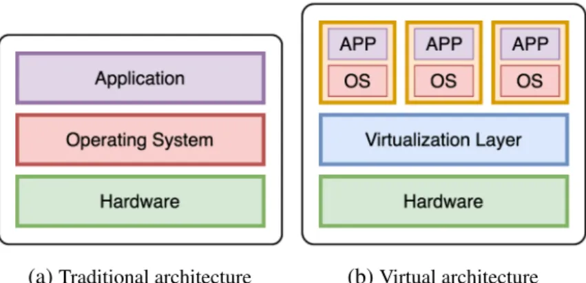
(a)Traditional architecture (b)Virtual architecture Figure 1.2 – Traditional and Virtual Architecture
Figure 1.2 shows the model of hardware virtualization, where the essential difference to the traditional one is a virtualization layer. In state-of-the-art virtualization systems, this layer is a software module called a hypervisor or also known as Virtual Machine Monitor (VMM), which works as an arbiter between a VM’s virtual devices and the underlying hardware. Hypervisor creates a virtual platform on a host computer, where multiple operating systems, which are either multiple instances of the same or different operating systems, can share the hardware resources offered by the host. This virtual environment is not only providing a sharing resources but also performance isolation, and security between running VMs. However, having to consult the hypervisor each time a VM makes a privileged call introduces a high overhead in the VM performance as the hypervisor must be brought online to process each request. This overhead can be mitigated depending on different virtualization mechanisms. Currently, we have two approaches to provide hardware virtualization: software-emulated virtualization and hardware-assisted virtualization.
1.3.1
Types of Hardware Virtualization
Software-Emulated Virtualization
In this solution, the hypervisor is responsible for the instruction emulation from VMs to physical devices. There are two distinct types of this virtualization scheme: full
virtualization and para-virtualization.
Full Virtualization is where the hypervisor holds the responsibility for the emula-tion of the instrucemula-tion from VMs to physical devices. In other words, a virtual machine can run with an unmodified guest operating system (using the same instruction set as the host machine) and it is completely isolated. A hypervisor emulates the physical hardware by translating all instructions from the guest OS to the underlying hardware. Full virtualization brings the compatibility and flexibility as a VM can run any OS with corresponding drivers and does not require any specific hardware, it also offers the best isolation and security for the virtual machines. However, this method has a bad performance due to the emulation of the hardware devices.
Figure 1.3 – The binary translation approach to x86 virtualization [2]
Figure 1.3 depicts the way a hypervisor combines the binary translation and the direct execution techniques to achieve full virtualization for CPU access. While a normal user level code is directly executed on the processor for high performance, a hypervisor has to translate kernel code to replace non-virtualizable instructions with new sequences of instructions that have the intended effect on the virtual hardware. Each hypervisor provides each VM with all the services of the physical system, including a virtual BIOS, virtual devices and virtualized memory management.
Para-virtualizationis different compared to full virtualization because the hyper-visor does not need to emulate the hardware for the VM. The VM is aware that it is running in a virtualized environment and it access hardware devices “directly” through special drivers, obtaining a better performance when compared to full virtualization. However, the guest OS kernel must be modified in order to provide new system calls. This modification increases the performance because it reduces the CPU consumption but, at the same time, it reduces the security and increases the management difficulty.
Figure 1.4 describes the Para-virtualization mechanism when a VM want to access to CPU core. Para-virtualization provides hypercalls for guest OS to communicate with the VMM directly. The hypervisor also provides hypercall interfaces for other critical kernel operations such as memory management, interrupt handling and time keeping.
1.3. Hardware Virtualization 15
Figure 1.4 – The Para-virtualization approach to x86 Virtualization [2]
Hardware-Assisted Virtualization
Hardware-assisted virtualization relies on special hardware to allow the instructions generated from guest OS to be directly executed on physical hardware. Because the X86 processor did not have such facilities available in its original design, this type of virtualization was used on the virtualization systems only from the 2000s when Intel and AMD introduced new level to the processor for the first time.
Figure 1.5 – The hardware assist approach to x86 virtualization [2]
As depicted in Figure 1.5, hardware vendors add a new privilege level to processor. This level is a new root mode, stays below ring 0. In the new privilege frame, when the guest OS attempts to perform the privileged operations, traps will be automatically raised to VMM without any binary translations. The new level lets the VMM safely and transparently uses direct execution for VMs to increase the performance of VMs. Moreover, the guest OS remains unmodified.
1.3.2
Discussion
All three above approaches have their own advantages and drawbacks. Full virtual-ization requires neither the OS modification nor the hardware modification, hence has the best compatibility. As VMWare has declared, full virtualization with binary transla-tion is currently the most established and reliable virtualizatransla-tion technology available [2].
And it will continue to be a useful technique for years to come. But the software imple-mented binary translation still has its inherence problems, such as memory accessing overhead, host CPU execution overhead. This is the inherence limitation of software approaches. So hardware assisted virtualization is where virtualization is going with pure software virtualization being a performance enhancing stopgap along the way.
Whatever the type of hardware virtualization, we always need a hypervisor to make the communication between the VM and the underlying hardware. The following sections will discuss two main elements inside a hardware virtualization environment: the hypervisor and the virtualized interfaces.
1.3.3
Hypervisor
Hypervisor is commonly classified as one of these two types, as show in Figure 1.6.
(a)Hypervisor Type 1 (b)Hypervisor Type 2 Figure 1.6 – 2 types of hypervisors
Type 1 - Bare-metal Hypervisoris also referred to as a "native" or "embedded" hypervisors in vendor literature. Type 1 hypervisor runs directly on the host’s hardware, meaning that the hypervisor has direct communication with the hardware. Consequently, the guest operating system runs on a separate level above the hypervisor. Examples of this classic implementation of virtual machine architecture are Xen, Microsoft Hyper-V, VMWare ESX.
Type 2 - Hosted Hypervisor runs as an application on a host operating system. When the virtualization movement first began to take off, Type 2 hypervisors were most popular used. Administrators could buy the software and install it on a server they already had. Some well-known examples of hosted hypervisor are VMWare Server and Workstation, QEMU, Microsoft Virtual PC, and Oracle VM VirtualBox. Full virtualization uses hosted hypervisor to manage VMs.
Type 1 hypervisors are gaining popularity because building the hypervisor into the firmware has been proved to be more efficient. According to IBM, Type 1 hypervisors provide higher performance, availability, and security than Type 2 hypervisors (IBM
1.3. Hardware Virtualization 17
recommends that Type 2 hypervisors should be used mainly on client systems where efficiency is less critical or on systems where support for a broad range of I/O devices is important and can be provided by the host operating system). Experts predict that shipping hypervisors on bare metal will impact how organizations purchase servers in the future. Instead of selecting an OS, they will simply have to order a server with an embedded hypervisor and run whatever OS they want.
1.3.4
Virtualized Interfaces
Many important operations in virtualized systems suffer from some degree of virtualization overhead. For example, in both full virtualization and paravirtualiztion, each time a VM encounters a memory page fault the hypervisor must be brought on the CPU to rectify the situation. Each of these page faults consists of several context switches, as the user space process is switched to the guest kernel, the kernel to the hypervisor, and sometimes the hypervisor to the host kernel. Compare this to a bare-metal operating system that generally has only two context switches: the user space process to kernel process and back again. Disk access has similar problems. It is fairly intuitive that the higher number of context switches and their associated operations can impart considerable overhead on privileged calls as each call now consumes considerably more CPU cycles to complete. As stated earlier, the hypervisor is necessary as it is required to operate between running VMs and the hardware for both performance isolation and security reasons.
The virtualized interfaces are concrete implementation of the two types of hardware virtualization techniques mentioned in Section 1.3. There are two types of virtualized interfaces in a virtualized environment: software-based interfaces and hardware-assisted virtual interfaces.
Software Interfaces
The virtual interfaces are generally considered to be in two classes: device emulation (fully virtualized) and paravirtualized devices.
Emulation of hardware devices is performed by the hypervisor. Since guest OS in VM only sees the emulated hardware, the VM can basically run on any hardware. However, emulation comes with a huge performance issue because the hypervisor needs to translate the communication of the VM and its emulated devices to the real physical hardware and back. For example, to emulate the CPU, the hypervisor has to capture all instructions sent to the processor by the VM, then translate them to use the real instruction set of the current physical CPU. After the CPU has finished the task, the hypervisor has to translate the result to the VM. In case of disk I/O from the guest OS, we can emulate the hard disk for a VM by mapping the I/O request addresses from the guest OS to the physical addresses and perform the read/write on the VM disk file on the host machine.
Para-virtualization lets the VM have special access to the hardware by using a modified physical hardware interface provided by the hypervisor. The guest OS has to be modified to make use of the paravirtualized interfaces. One of the most well-known implementation is virtio [27], which is used by KVM to provide par-avirtualized devices to VM. We have virtio-blk (parpar-avirtualized block device) and virtio-scsi (paravirtualized controller device) provide efficient transport for guest-host communication which improve the I/O performance of VM to hard disks, while virtio-ballon and virtio-mem tackle the problem of hot plug/unplug virtual memory for VMs.
Hardware-Assisted Interfaces
These interfaces are support by hardware companies. They add a new privilege level to the physical hardware devices so that a hypervisor can safely and transparently uses direct execution for VMs. The most known hardware-assisted interfaces are:
CPU: Intel VT-x [28], AMD-V [29]
They are two independent but very similar technologies by Intel and AMD which are aimed to improve the processor performance for common virtualization challenges like translating instructions and memory addresses between VM and the host. A VM can generate the instructions to change the state of system resources or the instructions executed by a program on a VM reveal that they were executed on a VM since the results differ from those when they are executed on the physical machine (e.g, htop command). These instruction can become the serious problem for the hypervisor and guest system. Both Intel VT-x and AMD-V were developed in response to this problem. It allows the hypervisor can execute these kind of instructions on behalf of the program.
Memory: Second Level Address Translation (SLAT)
A VM is allocated with virtual memory of the host system that serves as a phys-ical memory for the guest system. Therefore, the memory address translation has to perform twice – inside the guest system (using software-emulated shadow page table), and inside the host system (using hardware page table). Nested paging or Second Level Address Translation (SLAT) is a hardware-assisted virtualization technology developed to overcome overhead of hypervisor shadow page tables operations. Intel’s extended page tables (EPT) [30] and AMD’s Rapid Virtualization Indexing (RVI) [31] are implementations of the SLAT technology. Using SLAT, the two levels of address space translations required for each virtual machine is performed in hardware, reducing the complexity of the hypervisor and the context switches needed to manage virtual machine page faults.
Network: Virtual Machine Device Queues (VMDq)[32] and Intel Data Direct I/O Technology (Intel DDIO) [33]
They are devices focus on reducing the interrupt requests and remove the extra packet copy which happen when using a virtual NIC. When a VM transfers data through the network, the hypervisor is responsible for queueing and sorting the packets. VMDq
1.4. OS-level Virtualization (or Containerization) 19
moves packet sorting and queues out of the VMM and into the network controller hardware and allows parallel queues for each virtual NIC (vNIC). Intel DDIO allows the network data to exchange between the CPU and NIC directly without moving those packets to and from memory which help to reduce latency and enhancing bandwidth.
I/O: Single Root I/O Virtualization (SR-IOV) [34] and IO memory manage-ment unit (IOMMU)
Single Root I/O Virtualization (SR-IOV) [34], developed by the PCI-SIG (PCI Special Interest Group), provides direct access between the devices and the VM. SR-IOV can share a single device to multiple VMs. Also, IO memory management unit (IOMMU) allows guest VM to directly use peripheral devices through Direct Memory Access (DMA) and interrupt remapping.
1.4
OS-level Virtualization (or Containerization)
(a)Hardware Virtualization (b)Containerization Figure 1.7 – Virtualization Architecture
Containerization, also called based virtualization or application container-ization, is an OS-level virtualization method for deploying and running distributed applications without launching an entire VM for each application. Therefore, container-ization is considered a lightweight alternative to full machine virtualcontainer-ization. Figure 1.7 illustrates the differences between containers and VMs: (1) Containers run on a single control host and access a single kernel (Figure 1.7b), (2) VMs require a separate guest OS (Figure 1.7a). Because containers share the same OS kernel as the host, containers can be more efficient than VMs in term of performance. Essentially, containers are processes in the host OS that can directly call the kernel functions without performing many context switches as in the case of VMs.
The earliest form of a container dates back to 1979 with the development of chroot in 1979 in Unix V7, which created an early process isolation solution. There is no advancement in this field until the 2000s when FreeBSD Jails allows a computer system to be divided into multiple independent smaller systems. Then Linux VServer [35] used that jail mechanism to partition resources, which implemented by patching the Linux kernel. Solaris Containers [36], released in 2004, allows system resource controls and boundary separation provided by zones. In 2005, Open VZ [37] patched a Linux kernel to provide virtualization, isolation, resource management and checkpointing, however, it is not merged to the official Linux kernel. A major advancement in container technology happened when Google launched Process Containers [38] in 2006. It was later renamed to Control Groups - cgroups - and merged to Linux kernel 2.6.24. cgroupscan limit and isolate resources of a group of processes. Linux Containers (LXC) [39] was among the first implementation of a Linux container manager when it was introduced in 2008 that uses cgroups and namespaces. In the 2010s, Cloud Foundry with Warden and Google with Let Me Contain That For You (LMCTFY) are different solutions that tried to improve the adoption rate of the container technology. When Docker [40] emerged in 2013, containers gained huge popularity. At first, Docker also used LXC and later replaced with libcontainer. Docker can stand out from the rest dues to the whole container management ecosystem it brings to users.
Two most popular container technologies nowadays are LXC and Docker. Both utilize the Linux cgroups and namespaces in the Linux kernel to create an iso-lation environment for the containers. Essentially, Linux containers are just isolated processes with controlled resources running on a Linux machine. cgroups is a kernel mechanism for limiting and monitoring the total resources used by a group of processes running on a system. While namespaces are a kernel mechanism for limiting the visibility on the system’s resources that a group of processes has over the rest of a system. Accordingly, cgroups manages resources for a group of processes, whereas namespacesmanages the resource isolation for a single process.
1.5
Virtualization Overhead
While hypervisor-based technology is the current virtualization solution widely used in a cloud system, the container-based virtualization starts receiving more attention for being a promising alternative. Although container offers near bare metal performance and is a lightweight and faster solution compared to VM, both of these virtualization solutions still rely on sharing the host’s resource. They may suffer from performance interference in multi-tenant scenarios and their performance overheads would lead to negative impacts on the quality of cloud services.
To help fundamentally understand the overhead of these two types of virtualization solutions, we do a survey among studies that measure the overhead and compare the performance between VM, container and bare-metal. The results show that although the
1.5. Virtualization Overhead 21
container-based solution is undoubtedly lightweight, the hypervisor-based technology does not come with higher performance overhead in every case.
1.5.1
CPU Overhead
(a)1 Virtual CPUs (b)2 Virtual CPUs
(c)4 Virtual CPUs (d)8 Virtual CPUs Figure 1.8 – CPU Virtualization Overhead [3]
In Kumar’s thesis [3], he compared the CPU overhead between hardware virtual-ization (using both Xen and QEMU/KVM), containervirtual-ization (LXC), and bare-metal. The objective of the CPU test suite is to measure the execution time of the sample application and its individual tasks. His result depicts in Figure 1.8, which shows that Linux Containers and QEMU/KVM perform the best for both single-threaded and multi-threaded workloads, exhibiting the least overhead compared to the bare-metal performance. Though Xen performed identically to the others for single-threaded workloads, it exhibited relatively poor performance when scheduling multi-threaded workloads.
Other study [9] shows the difference in performance for CPU intensive workloads when running on VMs vs. LXCs is under 3% (LXC fares slightly better). Thus, the hardware virtualization overhead for CPU intensive workloads is small, which is in part due to virtualization support in the CPU (VMX instructions and two dimensional paging) to reduce the number of traps to the hypervisor in case of privileged instructions.
1.5.2
Memory Overhead
To evaluate the virtualization overhead associated with memory access, Kumar [3] created a sample application to allocate two arrays of a given size, and then copies data from one to the other. The reported “bandwidth” is the amount of data copied, over the time required for the operation to complete. Then, he measured the memory access bandwidth available to the virtual machine and bare-metal host. The results shows that Linux Containers and KVM yielded higher memory bandwidth than Xen.
The author in [9] measured the performance of Redis in-memory key-value store under the YCSB benchmark. For the load, read, and update operations, the VM latency is around 10% higher as compared to LXC.
1.5.3
Network Overhead
Kumar [3] measured the network bandwidth available to a virtual machine in both NAT and bridged configurations. To ensure a fair comparison, the author set up an iperf server on a machine outside of the test network and measured the network bandwidth by running an iperf client on each of VM/container. His results shows that there is no observable overhead introduced when virtualizing network interfaces hardware between virtualization (using both Xen and QEMU/KVM), containerization (LXC) and bare-metal.
The authors [9] also have the same conclusion, they do not see a noticeable difference in the performance between the two virtualization techniques when using the RUBiS benchmark to measure network performance of guests.
1.5.4
Disk I/O Overhead
Kumar [3] evaluated the overhead introduced when virtualizing disk I/O by per-forming a set of sequential and random disk I/O. He measured the execution time of the sample application and its individual tasks. The results summarized in Figure 1.9 confirm that KVM exhibiting the highest overhead, and Linux Containers exhibiting the least. Based on these results, the author concludes that Linux Containers perform the best with respect to virtualizing disk I/O operations.
The author [9] uses filebench randomrw workload which issues lots of small reads and writes, and each one of them has to be handled by a single hypervisor thread. VirtIO is used as I/O virtualized interface for VMs. Their results shows that the disk throughput and latency for VMs are 80% worse than Linux containers.
1.6. Summary 23
(a)Sequential File I/O (b)Random File I/O
(c)Disk Copy Performance
Figure 1.9 – Virtualization Overhead - I/O Disk (reads/writes) [3]
1.6
Summary
We have provided an overview of Cloud Computing from its beginning. A key component in the Cloud Computing technology is the virtualization, which comes in many different shapes and sizes. Even though virtualization brings many benefits to the Cloud system, it does not come without any trade-offs. In this chapter, we also discussed various overheads of virtualization. After having a general understanding of the concept of Cloud Computing, we present a crucial operation happens within a cloud system - the provisioning process, and we examine this operation in great detail in the following chapter.
2
IaaS Toolkits: Understanding a
VM/Container Provisioning Process
Contents
2.1 Overview . . . 26 2.2 Step 2: VM/Container Image Retrieval . . . 26 2.2.1 Retrieving Process . . . 26 2.2.2 Retrieving Process Issues and Solutions . . . 27 2.3 Step 3: Boot Duration . . . 29 2.3.1 Boot Process . . . 30 2.3.2 Boot Process Issues and Solutions . . . 31 2.4 Summary . . . 33
After drawing a high level picture about cloud computing and the role of virtualiza-tion technology, we focus in this chapter on the provisioning process of a cloud system (i.e., the process to allocate cloud provider’s resources and services to a customer). Because the provisioning process consumes resources, other running applications in the system can impact on this process duration. Besides, if we need an additional VM or container for a task, and the time to have that virtual environment ready is longer than the time that task finished, this leads to resource waste and unnecessary cost for the system. Therefore, optimizing the provisioning process is crucial in providing a better experience for users as well as improving the overall operations of the cloud system.
2.1
Overview
Cloud provisioning is the allocation of a cloud provider’s resources or services to a customer on demand and makes it available for use. In a typical cloud system, when a user requests to start a VM with specific resources, these following steps of a provisioning process are performed:
— Step 1: The scheduler identifies a suitable compute node for the VM/container based on the user requirements.
— Step 2: VM/container image is transferred from the repository to the designated compute node.
— Step 3: The VM/container starts its booting process on the compute node. All of these 3 steps are involved in the deployment duration of a new VM or container in a cloud platform. Depending on the properties of the client’s request (i.e., VM/container type, resources, start time, etc.), the availability of physical resources and the scheduling algorithm purpose (i.e., energy saving, resources usage, or QoS guarantee, etc.), the duration of operation in Step 1 can vary. In Step 2, the size of image, the I/O throughput on both compute node and repository and the network bandwidth between the compute node and the repository are important factors. Researchers usually consider that a VM launching process time takes place mostly in this stage and they try to speed it up [41, 42]. In Step 3, because the environment for the VM/container is ready, researchers assumed that the boot process utilise little resources and the time to boot that VM/container is negligible and can be ignored.
Step 1 is a well-known problem in cloud computing and there are thousand solutions according to the different purposes. Because the duration of Step 1 relies on the scheduling algorithm itself, this amount is not considered in total of a VM deployment time, and we do not focus on this step in our thesis. In general, the startup time or also known as launching time of a VM/container is consider as the last two steps. The previous works often skip the duration of step 3 [18, 41] or naively use a constant number to represent Step 3 duration [43]. Meanwhile, Step 3 may have significant effect on the total startup time of a VM as we explain further in part III. In the following sections, we introduce more detail about Step 2 and Step 3, we describe what happens in each Step and the current issues and solutions.
2.2
Step 2: VM/Container Image Retrieval
2.2.1
Retrieving Process
Generally, the images of VM/Container are stored in a centralized repository in most cloud system. Therefore in a provisioning process, we have to transfer the images from the repository to the assigned compute node before start a new VM/Container. Moving the image through out the network when deploying a machine puts a significant pressure
2.2. Step 2: VM/Container Image Retrieval 27
on the network capacity. In a shared environment, the degradation in performance of the network can have critical impact on the experience of other users in the system. When serving the images, the repository suffers from the workload on its I/O to retrieve the images from its local storage. In case the images are compressed before sending, the repository has to perform the compression task which is quite CPU heavy. This problem is more severe in case there are simultaneously deploying requests from users where the images need to be transferred to multiple physical nodes at the same time. Moreover, the compute node is also stressed on its CPU and IO.
2.2.2
Retrieving Process Issues and Solutions
The image of a VM/Container is, in fact, heavy in size and abundant. Each user is able to create or upload their own images. As a result, a number of storage nodes are dedicated to store images. When receiving user requests to create a new VM/Container, the image will be transferred from the storage nodes to the compute node, and this process becomes a burden to the cloud infrastructure. A lot of efforts focused on mitigating the penalty of the VM images (VMI) transferring time either by using deduplication, caching and chunking techniques or by avoiding it thanks to remote attached volume approaches [13, 14, 15, 44, 45]. On the contrary, there are only a few studies on improving container image transferring [16, 17, 46]. We give a summary of all techniques that present in these works in Table 2.1.
Table 2.1 – Summary methodologies to transferring images
Chunking Deduplication Caching Peer-to-Peer Lazy loading
VM [13] x x [14] x [44] x x [15] x [45] x Container [16] x [17] x [46] x VM Image Transferring
In this work, the authors [13] use deduplication technique on identical parts (chunks) of the images to reduce the required storage for VM disk images. They conducted extensive evaluations on different sets of virtual machine disk images with different chunking strategies. Their results show that the amount of stored data grows very slowly after the first few virtual disk images, which have similar kernel versions and
packaging systems. In contrast, when different versions of an operating system or different operating systems are included, the deduplication effectiveness decreases greatly. They also show that fixed length chunks work well compared to variable-length chunks. Finally, by identifying zero-filled blocks in the VM disks, they can achieve significant savings in storage.
Kangjin et al [44] propose a novel approach called the Marvin Image Storage (MIS) has which efficiently stores virtual machine disk images using a content addressable storage. For this purpose, the disk image is split in a manifest file which contains metadata information of each file in the image and the actual file content stored in the MIS data store. By using special Copy-On-Write layers, the MIS can reuse a virtual machine disk image as a shared base image for a number of virtual machines to further reduce the storage requirements. It also offers a fast and flexible way to apply updates. Furthermore, the MIS offers advanced features like hard link detection and algorithms to merge and diff image manifests, directly mount disk images from the store, an efficient way to apply updates to a disk image and the possibility to apply filters to remove sensitive content. The presented evaluation has shown that the storage requirements could be reduced by up to 94% of the original images. However, because they adopted the deduplication at the file level, they have to check the duplicated file content against the data store with each file in every VM image. This is an intensive CPU task which may effect the image server, especially in case the image server is transferring VM image to compute nodes.
Machine image templates are large in size, often ranging in tens of Gigabytes, thus, fetching image templates stored in centralized repositories results in long network delay. A solution to replicate the image repositories across all hosting centers is expensive in terms of storage cost. Therefore, a solution - called DiffCache [14] - which maintains a cache collocated with the hosting center to mitigate such latency issue is proposed. Generally, there is a high percentage of similarity between image templates, and this feature has been exploited in optimizing storage requirement of image repository by storing only common blocks across templates. DiffCache algorithm that populates the cache with patch and template files instead of caching large templates. A patch file is the difference between two templates, and if the templates are highly similar to each other then this patch file is rather small in size. As a result, DiffCache minimizes the network traffic, and leads to significant gain in reducing service time when compared to standard caching technique of storing template files. When the template and the patch file are in cache, then a new template can be generated by using the in-cache template and patch.
The key observation from the tests of the authors in [15] is that VMs actually read only small fractions of the huge VMI during the boot process, with ≈200 MB being the biggest size observed from a Windows Server 2012 image. Therefore, they proposed VMI caches, as an extension to QCOW2 format, that can significantly reduce the amount of network traffic for booting a VM. The authors made use of the characteristics of
2.3. Step 3: Boot Duration 29
the copy-on-write mechanism to populate the VMI caches during the boot process of VMs. This cache is chained, and positioned between the base image and the COW layer. Whenever a VM needs the boot data from the base image, it can read from the warmed cache, which reduce the IO to the base image and speed up the process.
Nicolae et al. [45] introduced a novel multi-deployment technique based on aug-mented on demand remote access to the VM disk image template. Since the IO is performed on-demand, it prevents bottlenecks due to concurrent access to the remote repository. The authors organized VMs in a peer-to-peer topology where each VM has a set of neighbors to fetch data chunks from. The VM instances can exchange chunks asynchronously in a collaborative scheme similar to peer-to-peer approaches. The scheme is highly scalable, with an average of 30-40% improvement in read throughput compared to simple on-demand schemes.
Container Image Pulling
Slacker [16] is a new Docker storage driver utilizing lazy cloning and lazy propa-gation to speed up the container startup time. Docker images are downloaded from a centralized NFS store and only a small amount of data needed for the startup process of the container is retrieved. Other data is fetched when needed. All container data is stored in the NFS server which is shared between all the worker nodes. However, this design tightens the integration between the registry and the Docker client as clients now need to be connected to the registry at all times (via NFS) in case additional image data is required.
CoMICon [17] proposes a cooperative management system of Docker images on a set of physical nodes. In each node, only a part of images is stored. CoMICon uses peer-to-peer (P2P) protocol to transfer layers between nodes. When an image is pulled, CoMICon tries to fetch a missing layer from a closest node before pulling from a remote registry.
FID [46] is a P2P-based large-scale image distribution system, which integrates the Docker daemon and registry with BitTorrent. A Docker image is stored in the Docker Registry as two static files: the manifest and the blobs. Blob is a compressed file of the layer. When images are pulled, the blobs are downloaded using P2P. For each blob, a torrent file is created and seeded to the BitTorrent network. Because BitTorrent is used to distribute images, it exposes Docker clients to other nodes in the network which can become a security issue.
2.3
Step 3: Boot Duration
In this section, we describe a VM and container boot process so that readers can understand clearly the different steps of the boot operation. From that, we can have an idea of the level of influence of these factors on the boot time of a VM or container.
2.3.1
Boot Process
VM Boot Procces
- Check Hardware - Start Boot Loader
Run Scripts Context
Assign
Devices Load and Init Kernel
Figure 2.1 – VM boot process
Figure 2.1 illustrates the different stages in a VM boot process. During a VM boot operation, a standard OS boot process happens. First, the hypervisor is invoked to assign resources (e.g., CPU, memory, disk storage) to the VM. After that, BIOS checks all the devices and tests the system, then BIOS loads the boot loader into memory and gives it the control. Boot loader (GRUB, LILO, etc.) is responsible for loading the OS kernel. Finally, the OS kernel starts the configured services such as SSH. The last step is made based on client requirements. A VM boot process generates both read and write operations: it loads the kernel files from the image into memory and writes the data (logs, temporary files, etc.).
Container Boot Process
Figure 2.2 – Container boot process
Although we use the words container boot process in comparison with the hardware virtualization system terminology, it is noteworthy that a container does not technically boot, but rather start. The overview of the container boot process is depicted in Figure 2.2. Booting a docker starts when the dockerd daemon receives the container starting request from the client. After verifying that the associated image is available, dockerd utilizes cgroups and namespace to prepare the container layer structure, initializes the network settings, performs several tasks related to the specification of the container and finally gives the control to the containerd daemon. containerd is in charge of starting the container and managing its life cycle.
2.3. Step 3: Boot Duration 31
Summary
CPU, memory, and IO resources from the compute node are required to achieve the boot process. Consequently, workloads or VMs/containers that are already executed on the compute node can significantly increase the VM/container boot time and should be considered in a boot operation.
2.3.2
Boot Process Issues and Solutions
The promise of elasticity of cloud computing brings the benefits for clients to add and remove new VMs in a manner of seconds. However, in reality, users must wait several minutes to start a new VM in the public IaaS cloud such as Amazon EC2, Microsoft Azure or RackSpace [18]. Such long startup duration has a strong negative impact on services deployed in a cloud system. For instance, when a web service faces spontaneously increasing workloads in the high sale season, they need to add new VMs temporarily. The websites may be unreachable if the new VMs are only available after a few minutes, leading to unsatisfied clients and a loss of revenue for the site operators. Therefore, the startup time of VMs is also essential in provisioning resources in a cloud infrastructure.
While a lot of efforts focused on speeding up the VMI transferring time, there are only few works that focus on the startup/boot operation. To the best of our knowledge, the solutions that have been investigated rely on the VM cloning technique [47, 48, 49, 50] or the suspend/resume capabilities of VMs [51, 52, 53, 54]. The cloning solutions require to keep a live VM on a host to spawn new identical VMs so that they skip the whole VM boot process. Moreover, after cloning, VMs need to be reconfigured to get specific parameters such as IPs or MAC addresses. With the resuming technique, the entire VM state is suspended and resumed when necessary. This mechanism has to store a significant number of VMs due to the variety of requested applications and configurations. In our discussion, we analysed the works that focus on improving the VM booting phase by using two techniques: cloning and resuming.
Cloning
SnowFlock [47] and Kaleidoscope [48] are similar systems that can start stateful VMs by cloning them from a parent VM. SnowFlock utilises lazy state replication to fork child VMs which have the same state as a parent VM when started. Kaleidoscope has introduced a novel VM state replication technique that can speed up VM cloning process by identifying semantically related regions of states.
Potemkin [49] uses a process, called flash cloning, which clones a new VM from a reference image in the compute node by copying the memory pages. To create the reference image, Potemkin initiates a new VM then snapshot the VM memory pages. After changing its identity (i.e., IP address, MAC address, etc.), the newly cloned VM is already ready to run without going through the VM boot process. Potemkin presents an optimization by marking the parent VM memory pages as copy-on-write and
![Figure 1.1 – Overview of Grid and Cloud computing, updated version of [1]](https://thumb-eu.123doks.com/thumbv2/123doknet/7872844.263547/26.892.304.650.258.532/figure-overview-grid-cloud-computing-updated-version.webp)
![Figure 1.8 – CPU Virtualization Overhead [3]](https://thumb-eu.123doks.com/thumbv2/123doknet/7872844.263547/36.892.199.759.322.701/figure-cpu-virtualization-overhead.webp)
![Figure 1.9 – Virtualization Overhead - I/O Disk (reads/writes) [3]](https://thumb-eu.123doks.com/thumbv2/123doknet/7872844.263547/38.892.186.783.167.536/figure-virtualization-overhead-i-o-disk-reads-writes.webp)


![Figure 3.6 – Docker union file system: overlayfs [4]](https://thumb-eu.123doks.com/thumbv2/123doknet/7872844.263547/55.892.163.663.675.796/figure-docker-union-file-system-overlayfs.webp)


