HAL Id: hal-03034868
https://hal-cnrs.archives-ouvertes.fr/hal-03034868
Submitted on 1 Dec 2020
HAL is a multi-disciplinary open access
archive for the deposit and dissemination of
sci-entific research documents, whether they are
pub-lished or not. The documents may come from
teaching and research institutions in France or
abroad, or from public or private research centers.
L’archive ouverte pluridisciplinaire HAL, est
destinée au dépôt et à la diffusion de documents
scientifiques de niveau recherche, publiés ou non,
émanant des établissements d’enseignement et de
recherche français ou étrangers, des laboratoires
publics ou privés.
realistic conditions
Arthur Julien, Jean-Baptiste Puel, Pilar Lopez-Varo, Jean-François
Guillemoles, Stéphane Collin
To cite this version:
Arthur Julien, Jean-Baptiste Puel, Pilar Lopez-Varo, Jean-François Guillemoles, Stéphane Collin.
Backside light management of 4-terminal bifacial perovskite/silicon tandem PV modules evaluated
under realistic conditions. Optics Express, Optical Society of America - OSA Publishing, 2020, 28,
�10.1364/oe.405713�. �hal-03034868�
Backside light management of 4-terminal
bifacial perovskite/silicon tandem PV modules
evaluated under realistic conditions
A
RTHURJ
ULIEN,
1,2,5,6J
EAN-B
APTISTEP
UEL,
1,3,5,7P
ILARL
OPEZ-V
ARO,
1J
EAN-F
RANÇOISG
UILLEMOLES,
1,2 ANDS
TÉPHANEC
OLLIN1,41IPVF, Ile-de-France Photovoltaic Institute, 91120 Palaiseau, France
2CNRS, UMR 9006, Ile-de-France Photovoltaic Institute, 91120 Palaiseau, France 3EDF R&D, 91120 Palaiseau, France
4Centre for Nanoscience and Nanotechnology, CNRS, Univ. Paris-Sud, Université Paris-Saclay, 91120
Palaiseau, France
5Equally contributed to this work 6arthur.julien@supelec.fr 7jean-baptiste.puel@edf.fr
Abstract: Perovskite/silicon tandem modules have recently attracted growing interest as a
potential candidate for new generations of solar modules. Combined with a bifacial config-uration it can lead to considerable energy yield improvement in comparison to conventional monofacial tandem solar modules. Optical modeling is crucial to analyze the optical losses of perovskite/silicon solar modules and achieve efficient light management. In this article we study the optical properties of four-terminal bifacial tandem modules, using metal-halide perovskite top solar cell and a conventional industrial crystalline silicon PERC bottom solar cell. We propose a method to analyze bifacial gains, improve back side light management and challenge it under realistic spectral conditions at several locations with various albedos. We show that both optimized designs for the back side show comparable advantages at all locations. These results are a good sign for the standardization of bifacial four-terminal perovskite/silicon modules.
© 2020 Optical Society of America under the terms of theOSA Open Access Publishing Agreement
1. Introduction
Perovskite/silicon tandem modules have the potential to reach conversion efficiency around 40% [1], overcoming the Shockley-Queisser limit of single junction solar cell around 33% [2]. With highly efficient perovskite top cell and rapid improvement of devices figures of merit, it is now possible to consider overcoming 30% efficiency in the near future. Four terminal tandem device is one of the configurations which does not require electrical matching, allows optimizing silicon and perovskite cells independently, and is less affected by outdoor conditions than monolithic tandem modules [3–5]. This leads to more flexibility in the design of the device, but with losses such as parasitic absorption of the transparent conductive layers. So far, several works detailed optimizations of perovskite/silicon tandem devices for various configurations [3,6–11]. Additional gains are possible by using perovskite/silicon tandem module in a bifacial configuration [12–15]. However, there have been few works on optical modeling of bifacial four-terminal configuration considering a full module stack, including spectral contributions.
In this article we present a detailed analysis of back light management and optimizations depending on surroundings, albedo conditions and spectral effects. The methodology developed helps analyzing four-terminal perovskite/silicon modules. We carry out modeling by combining Monte Carlo ray tracing, thin-film optics and multiphysics realistic modeling of the energy yield (electrical, spectral and optical). First, the model used is detailed (see Section2) and applied
#405713 https://doi.org/10.1364/OE.405713 Journal © 2020 Received 21 Aug 2020; revised 11 Nov 2020; accepted 11 Nov 2020; published 30 Nov 2020
to estimate the gain induced by considering the bifacial module in comparison to the classical monofacial module (see Section3). A better understanding of the mechanisms involved, and thus the added-value of bifaciality, is detailed (see Section4). Then back texture optimizations are studied for several albedo conditions. Light management improvements are performed by maximizing the photocurrent density of the architecture. It is shown that texturing back silicon and/or back glass module depends on the albedo conditions. At the end, the optimized structures are evaluated in realistic spectral conditions (Section5). Several locations covering a wide range of climate possibilities are considered. This allows evaluating the energy yield gain of bifacial four-terminal module stack depending on back light management optimizations, albedo conditions, and locations.
2. Modeling methods
2.1. Optical modeling of tandem solar modules
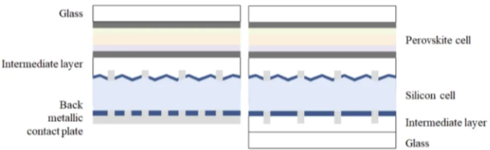
Optical modeling was performed with SunSolve [16] to obtain A(λ, θ) with A the absorption, λthe wavelength and θ the incident angle. This tool combines Monte-Carlo-based ray tracing with thin-film optics. Ray tracing was used with optically thick layers where light propagates incoherently such as silicon textured layer, glass, and intermediate matching layers (IML). Transfer matrix method was then used to simulate coherently thin films included in ray tracing simulation at interfaces. A sufficiently large number of rays were used so that the Monte Carlo simulation converges to the physical model. Simulations were performed using the structures presented in Fig.1. Direct (normal or with an incidence angle) or totally diffuse incoming light are simulated.
Fig. 1. Monofacial (left) and simple bifacial (right) module structure. For the bifacial
module the back silicon contact grid is modified, IML and a glass layer are added.
Thicknesses and optical indices (Table3, Appendix) for the perovskite stack are obtained through in-house experimental measurements performed on samples produced at IPVF [17]. PERC silicon solar cell is considered in order to study mainstream industrial solar cells. 2.2. Spectral modeling and energy yield estimation under realistic conditions
Spectral modeling methodology is now detailed. This part of the home-made code aims at determining direct and diffused irradiance spectra typically perceived by a solar module. Depending on location, ground albedo and surroundings, representative irradiance data at each hour in a theoretical year are computed. To do so, it associates Typical Meteorological Year data (TMY3 data provided by NREL [18]) and a spectral irradiance modeling tool: SMARTS2 [19]. Irradiance perceived at the front is the sum of direct and diffuse components. Irradiance perceived at the back of the module is essentially diffuse and results from sky diffusion and reflection on surroundings.
An optimal module inclination is beforehand determined by minimizing the incidence angle of direct sun irradiance over a year. In order to account for the complex influence of surroundings, a view-factor computation code is developed, based on the pv-factors python library [20]. Having
the module position fixed, the view-factors computation code calculates the broadband irradiance power of the following components: sky diffused, reflection on surrounding modules and reflection on ground, perceived at the front or the back side of the solar module (see Fig.2). The spectral shape of these components is computed in parallel, based on SMARTS outputs, combined with spectral albedo and reflectance of the photovoltaic modules. Previous view-factor results are finally used to set the broadband power of these components.
Fig. 2.Decomposition of the irradiance perceived at the front and back sides of a photovoltaic
module in a field configuration.
Photogenerated currents are obtained from the module optical simulation detailed previously, using A(λ, θ) as input. These currents are computed considering front and back illumination contributions and are used to evaluate optimizations.
A one diode model is used for the electrical modeling and parasitic resistances are considered. The photogenerated current is used to compute the short circuit current, open circuit voltage, fill factor and output power for each sub-cell, at each timestep. Values of electrical parameters such as shunt and series resistances or ideality factors are taken from literature [21,22]. Such electrical model gives reasonably accurate results and can be rapidly used [14,15], simulations are run over the 8760 hours of a year.
The temperature of the solar cells is estimated by using a model depending on ambient temperature, wind speed and global irradiance perceived at the front side [23]. Both sub-cells are considered having the same temperature, and the thin perovskite stack having low influence on the module temperature. Parameters of the model are chosen for crystalline silicon modules mounted on a free-standing rack (in a solar farm for instance) [24]. The impact of cell temperature on the output power is modeled with temperature coefficients: - 0.17%/K [25] for the perovskite and -0.39%/K [26] for the silicon. The output power is the only quantity used to compute energy
yield.
3. Gain of bifacial over the monofacial module
In a first step, before analyzing optimization guidelines linked to bifacial structure, a monofacial structure was compared to a bifacial tandem module by removing the back contact metallic plate, implementing the same grid as the silicon cell front side and adding index matching and glass layers, see Fig.1.
The optical behavior of both cells is investigated under AM1.5g irradiance at normal incidence angle on the front side and without considering incoming light at the back side. In that way, monofacial and bifacial modules are compared, without considering the back optical gain in the bifacial module. Photogenerated current remains at 20.1 mA.cm−2in the perovskite cell and goes
from 12.79 to 12.70 mA.cm−2in the silicon, for the monofacial and bifacial modules, respectively.
photocurrent. In Fig.12(Appendix), it is noticeable that losses through back encapsulant absorption and back escape in the bifacial device are of the same order of magnitude as metal absorption in the back metallic plate of the monofacial one.
In a second step, the gain of the bifacial module was studied by additionally taking into account the irradiance at the back side, which is in real conditions mainly composed of diffused light reflected by the surrounding. It is thus important to consider spectral albedo to estimate its power and spectral repartition, rather than classical AM1.5g. Six spectral albedo values available in the literature are used to provide a realistic view of the diversity of the possible surroundings of the modules (see Fig.3). The spectrum of the input irradiance at the back of the module is computed as the product of AM1.5g spectrum with this albedo. The position of solar module in relation with the ground or other photovoltaic modules influences this input irradiance. In order to account for these geometrical aspects, the power of all irradiances is reduced by the same factor. This coefficient is set in such a way that the perceived power represents approximatively 35 and 15% of the total power of the AM1.5g spectrum for sand and grass albedo, respectively. This value is computed in regards to usual gains observed with bifacial modules ( [27,28]). Light at the backside is considered as totally diffuse in the model and generated by an isotropic source located at the back of the module.
Fig. 3.Spectral albedo of the six materials considered.
The comparison in Table1between monofacial and bifacial modules, taking advantage of this supplementary input light at the back, shows that a strong photogenerated current improvement and energy production gain can be expected. The relative current gain in the silicon cell reaches important values, due to the low optical losses at the back of the bifacial device, showed in Fig.12
(Appendix).
Figure4shows absorption/reflection of the monofacial and bifacial modules for the case of sand albedo, (A) and (B), and grass albedo, (C) and (D), respectively. Additional available light is completely absorbed by the bottom silicon cell. This shows a strong advantage of the four-terminal bifacial modules over two-terminal ones, as no current matching is necessary, thus avoiding the need to adapt the device design according to the module surroundings. In this graph both front and back illuminations are considered even in the case of monofacial configuration. Even if monofacial do not use the amount of light coming from the back, it is used in order to be in the same conditions in the monofacial graph (A and B) and bifacial graph (C and D). This helps visualizing the effect of bifaciality on silicon and the back side of the device. The white
Table 1. Current photogeneration computed in tandem module. The monofacial device (first column) is only illuminated under direct AM1.5g spectrum at the front, the bifacial module (other columns) is illuminated by the same front light and supplementary diffuse light coming from several
albedos at the back. The irradiance power is only computed over the 300-1200 nm spectral range.
AM1.5g
(monofacial) Sandalbedo Grassalbedo Asphaltalbedo Concretealbedo Snowalbedo Soilalbedo Input power (mW.cm−2) 83.39 113.06 95.47 86.64 94.75 123.03 88.5
Photogenerated current in
silicon cell (mA.cm−2) 12.80 24.13 17.85 13.92 17.10 27.18 14.85
Relative input gain (%) 35.6 14.5 3.9 13.6 47.5 6.1 Relative current gain in
silicon cell (%) 88.5 39.5 8.7 33.6 112.3 16.0
Fig. 4. Absorption, reflection and loss analysis. Monofacial module with sand (A) and
grass (C) surrounding albedo, bifacial module with sand (B) and grass (D) surrounding albedo. Front irradiation is direct AM1.5 g spectrum in all cases. Back irradiation with diffuse light, is considered in both cases for the sake of comparison explaining the “Back reflection” area in the monofacial case.
area corresponds to the remaining front reflections and parasitic absorptions from other layers of the device, and back reflection represents the amount of light reflected at the back side with back illumination.
4. Design improvements of the bifacial structure
4.1. Enhanced front glass performances
In order to study light management optimization guidelines, we start from considering the front part of the module including MgF2glass antireflection coating (ARC) and front glass random
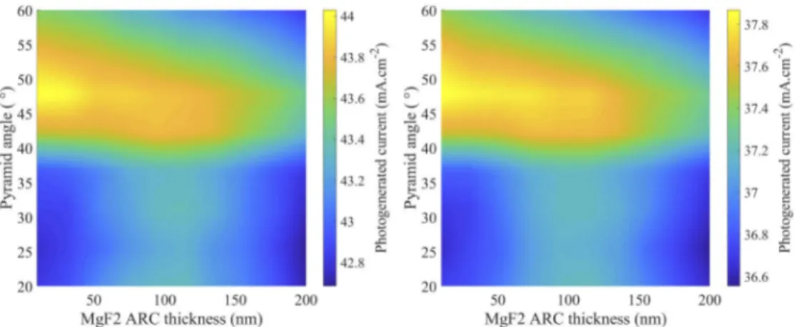
pyramidal texture. Such textured glass is already obtained by [29] using a textured nanoimprinted foil with a refractive index sufficiently similar to glass. To optimize these features, the pyramid base angle is varied from 20° to 60°, keeping the 5 µm height constant. The ARC thickness is swept from 10 to 200 nm. The pyramid shape is therefore modified, which is the decisive aspect impacting the optical behavior as shown before [29]. As a bifacial module is designed, backside illumination is considered to evaluate the dependence of the optimal design on module surroundings conditions. Figure5shows the front side optimization when light reflected from sand or a grass ground (differing albedo values) is illuminating the back side of the device. First, results are highly similar, confirming that no significant quantity of light entering at the back side reaches the front side of the device. Furthermore, the pyramid shape influences more the current generation than the ARC thickness, even making the current independent from the film thickness in some cases. One can note that in the lower part of the graphs, where the texture is almost planar, the ARC slightly improves the absorption with usual thickness around 100 nm.
Fig. 5.Photogenerated current in the bifacial tandem module as a function of front glass
texture pyramid base angle and ARC thickness. The module is illuminated by direct AM1.5 g spectrum at the front and diffuse light coming from sand (left) and grass (right) albedo.
As expected no ARC is needed when considering textured glass. For the studied bifacial tandem module, the optimal angle is 46° for both illumination cases. This allows the current in the tandem to reach 46.70 mA.cm−2with sand albedo and 40.22 mA.cm−2with grass albedo.
4.2. Back interface optical behavior
Due to various albedo contributions, light management optimization must be done in consideration of possibly very different incoming light spectra. It is expected to be influenced by the back of the tandem module, for instance when specific textures are employed, here the roles of silicon back-side texture and back glass layer texture are investigated by modeling four devices shown in Fig.6. The textures are random pyramids, 5 µm high with a 52° base angle, which have been
shown to be the best parameters to model the commonly processed silicon wafers in alkaline solutions [30].
Fig. 6. Structure of the modeled bifacial modules. Modules with either: no silicon and
glass back-side texture (a), only glass back texture (b) or silicon back texture (c), or both glass and silicon back-side textures (d) are investigated.
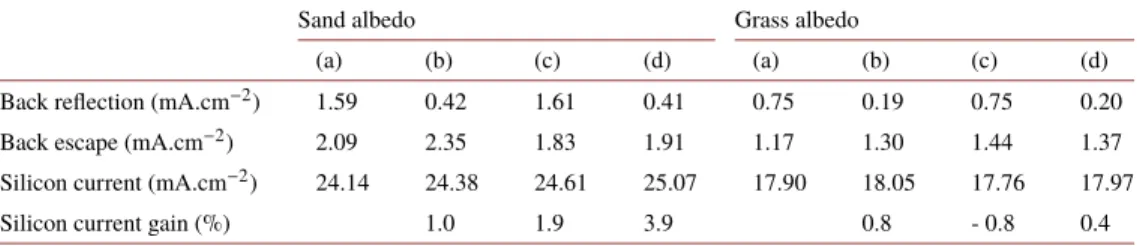
Photogenerated currents in these four devices are shown in Table2, the incoming light at the back side is considered diffuse, either as coming from a sand or grass albedo. It can be first noticed that in both cases, (b) and (d) devices are respectively generating more current than (a). It means that having a textured glass interface improves the design of the back of a bifacial module as it does for the front side.
Table 2. Losses through reflection or back side light escape and current photogeneration in the silicon cell. The front irradiance is direct AM1.5g spectrum; the light from the back is diffuse and
coming from either sand or grass albedo. (a) (b) (c) and (d) devices are defined in Fig.6.
Sand albedo Grass albedo
(a) (b) (c) (d) (a) (b) (c) (d) Back reflection (mA.cm−2) 1.59 0.42 1.61 0.41 0.75 0.19 0.75 0.20
Back escape (mA.cm−2) 2.09 2.35 1.83 1.91 1.17 1.30 1.44 1.37
Silicon current (mA.cm−2) 24.14 24.38 24.61 25.07 17.90 18.05 17.76 17.97
Silicon current gain (%) 1.0 1.9 3.9 0.8 - 0.8 0.4
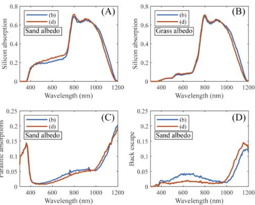
Nevertheless, the best structure is not the same with both albedo conditions, yielding potential optimization for specific locations or surroundings of the solar panel. It appears that the silicon back-texture is advantageous for strong (sand) albedo, and detrimental for low (grass) albedo. This varied behavior can be understood by looking at spectral absorption in silicon in Fig.7(A) and (B). Under 1000 nm the absorption is higher when the silicon back-side is textured: device (d). On the contrary, a flat silicon back-side is advantaged for longer wavelengths: device (b). The slight advantage of non-textured silicon over textured silicon in the grass-surroundings case comes from the low backside incident power below 700 nm (see Fig.3).
The inversions at 1000 nm also occurs for the parasitic absorptions in the layers at the back of the silicon cell (dielectrics, IML, glass) and for the light escaping at the back, see Fig.7(C) and (D). Below 1000 nm most of the light coming from the device front side is absorbed before reaching the back of silicon, the absorption and light escape differences occurring between device structures are thus due to back-side light management variations. For device (d), lower parasitic absorptions, lower back escape and higher absorption in silicon clearly confirm, that the silicon pyramidal texture improves the penetration of light coming from the back into silicon by reducing its surface reflection.
At longer wavelengths, the back silicon texture has an influence on the light coming from the front device side, as all infrared radiations are not absorbed in a single pass. Parasitic absorptions remain stable but back escape rises with the introduction of texture at the backside of silicon.
Fig. 7.Silicon absorption in bifacial devices: (A) and (B). Parasitic absorptions in back
silicon dielectrics, IML and glass: (C), and escaping light through the back of the devices: (D). Direct AM1.5 g spectrum at the front and diffuse light coming from sand albedo: (A), (C) and (D), or grass albedo: (B). Devices have only a glass texture (b) or both glass and silicon textures (d).
This might indicate that the infrared (IR) light coming from the front is less trapped in the silicon layer: it escapes the silicon (less absorption), goes through the back-side materials and escapes the device.
These results show a compromise between benefits of front side illumination (reflection of front IR at the back side) and benefits of back side illumination (penetration of back illumination). In this context textured back silicon interface favors back light penetration against front IR reflection. The optimal structure in high albedo conditions (such as sand albedo) uses both textures at the back of silicon and glass. On the other hand, when the albedo is low, as in the case of grass albedo, keeping a flat back silicon side is favorable. In any case, a textured back glass interface shows advantages to increase the quantity of light entering into the device from the back. 4.3. Enhanced back side
Back side silicon and glass textures were previously all modelled as random pyramids, 5 µm height, with a 52° base angle. The textured shape of the glass is now varied and an ARC is considered. To find an optimal interface the pyramid base angle is varied from 20° to 89° and the MgF2thickness from 10 to 200 nm. Unlike front incoming light, back irradiance is considered as
totally diffuse, it is also much less intense. The photogenerated current variations are thus much smaller in Fig.13(Appendix) than in Fig.5. Actually, when the ARC thickness is adjusted, any pyramid angle can be chosen and results in a loss of less than 0.2 mA.cm−2.
Simulations show that the best results are obtained with a pyramid texture of more than 80° angles. Because of small current gain and of device production issues, we can consider that
for instance the 52° base angle used previously is suitable. Such a pyramid shape has the great advantage of being commonly obtained with silicon etching, allowing nanoimprint method in order to obtain pyramids at the glass surface [31].
In comparison to the simple bifacial module, improved devices show more than 0.7 mA.cm−2
increase in the perovskite cell and respectively 0.9 mA.cm−2and 0.2 mA.cm−2for both textured
back interface in sand conditions and the only glass textured back interface in grass conditions. The 4-terminal tandem module reaches 45.85 mA.cm−2and 38.84 mA.cm−2in sand and grass
albedo conditions, respectively. Interestingly, the same back texture is shown to work almost equally well for all albedo.
5. Bifacial tandem modules under realistic conditions
5.1. Irradiance spectra along the year at several locations
The in-house code allows obtaining spectral irradiations consistent with typical meteorological year irradiance for a given location. The combination with geometrical modeling through view-factors provides spectral results for all components of the perceived light at the front or back side of a photovoltaic module. Figure8shows that on average the main components impacting the front side are the sun irradiance directly perceived and diffused by the sky. On the other hand, the composition of the irradiance perceived at the back side is more complex. Minor components (sky diffused and reflected on the facing module) are of substantial magnitude and have to be considered in order to accurately simulate the spectrum of perceived irradiance.
Fig. 8. Spectral irradiance perceived at the front side (left) and back side (right) of a
photovoltaic module. Spectra are averaged over a year. Location is Denver and a grass albedo is considered. PV reflected is the component that is reflected on the facing module (see Fig.2).
Calculated data accounts for usual sunshine variations (due for example to cloudiness, humidity, temperature, pressure variations) along a representative year for the given location. It is important to consider irradiance spectrum shape variations as both sub-cells are not impacted in the same way. Figure14(Appendix) shows for instance that absorbed spectra shift towards short wavelength along the morning (independently from the global intensity increase). The longer path through the atmosphere when the sun is low results in more Rayleigh scattering (which impacts more short wavelengths than longer wavelengths).
When considering several locations, the shape of irradiance also varies and the site’s latitude is of noticeable influence. Sun zenith angle along the year is directly linked, making the average spectrum of normal direct irradiance IR-richer in Seattle than in Las Vegas. Table4(Appendix)
shows the relevant characteristics of the three locations compared. Las Vegas is characteristic of the hot and dry climate, Denver is rather hot but more humid, and finally, Seattle is representative of temperate climates, these three locations give a sample group of possible operative conditions for the modules. Combined with the variations observed in irradiance spectra, this study gives keys to investigate the optical behavior of the enhanced bifacial tandem modules and evaluate their improvements under realistic conditions.
5.2. Energy yield gain of the optimized device
Spectral irradiation perceived at front and back side of the module, when combined with optical modeling previously presented, allows determining photogenerated currents in the devices. As perovskite and silicon cells do not absorb the same part of the spectrum, current productions evolve differently during a day. At the beginning and the end of the day, when the sun is low and perceived spectrum is IR-richer, both currents have closer values: at these specific moments the silicon cell might give better results. The same phenomena might play a role with a higher difference in summer than in winter (also IR-richer spectra).
Absorbed spectral irradiance in each sub-cell can be converted into photon flux and then into spectral photogenerated current. Combined with the open circuit voltage and fill factor of the cells, a spectral output power is computed. Figure9shows such result for the yearly averaged spectra of each component (see Fig.2). perceived at the front or back side and when considering sand or grass albedo. Year-average open circuit voltages and fill factors are considered. This interestingly shows that, at the front side, the silicon solar cell absorbs mainly direct irradiance, unlike the perovskite cell. The small quantity of ground-reflected irradiance perceived at the front side is almost entirely used by the perovskite cell, in the case of a sand albedo. At the back side, the components diffused by the sky and reflected on the facing module bring a perceptible supplement of energy, with a strongly different spectral distribution from the ground-reflected component.
The irradiance spectra of the three locations presented in Table4(Appendix) are used to estimate the current and output power gain of the enhanced devices in part 4. Results for “Reference monofacial” and “Reference bifacial” modules in Fig.10show the energy production gain through bifaciality without light management optimization. It is more significant when the albedo is stronger: in the case of sand (left) it lies between 16.5% at Las Vegas and 18.8% at Seattle. In the case of grass, the gain remains between 6.6% and 10.0%.
Both optimized bifacial devices show superior performances: their front side is improved through textured glass, and their back side is optimized either for high or low reflecting albedo. The fully back textured device (“Sand-optimized bifacial”, (d) in Fig.6) is developed for high reflective sand albedo, the device with flat silicon back interface (“Grass-optimized bifacial, (b) in Fig.6) is optimized for low reflective grass albedo. The advantage of having a device with back light management optimized for a specific albedo is perceptible but appears limited. Two factors might be in cause: first, the irradiance power perceived at the back is too low for its spectral variations to have a significant influence on device performances. Second, the irradiance perceived at the back side is not entirely coming from reflection on the ground, but also from reflections on surrounding photovoltaic modules and sky diffusion, as seen in Fig.9. For instance, a module installed at Denver over a grass albedo would perceive 130.4 kWh.m−2per year through
reflection on the ground and 30.2 kWh.m−2per year directly from sky diffusion. Only the ground
reflected component is influenced by spectral albedo variations.
The fully textured back interface device (“Sand-optimized bifacial”, (d) in Fig.6) is slightly more flexible to both albedo conditions. It brings a yield gain over the “Reference monofacial” device between 8.0% in Las Vegas with grass albedo and 20.4% in Seattle with sand albedo. It appears clearly that bifacial photovoltaic modules bring the most benefits over monofacial modules under low irradiance climates (it is temperate or slightly humid in Seattle). Here
Fig. 9.Spectral output power of the perovskite cell (dark colors) and the silicon cell (light
colors). The considered module is optimized for strong albedo conditions (d) in Fig.6). Average irradiance spectra from Denver with a sand albedo (a) and b)) or a grass albedo (c) and d)) are considered. a) and c) show the front side, b) and d) the back side.
Fig. 10. Energy production estimation in realistic conditions at three locations for sand
(left) and grass (right) albedo. Reference modules are presented in Fig.1, enhanced bifacial devices are presented in Fig.6(b) and (d).
the diffuse irradiance perceived at the back side is of more weight, than in cases where direct irradiance perceived at the front is already very powerful (such as Las Vegas).
5.3. Remaining energy yield losses
Detailed optical losses obtained from optical simulation are spectrally separated into two parts: occurring at lower or higher wavelength than the perovskite bandgap. They are therefore divided in losses for the perovskite or losses for the silicon. With the same method as for photogenerated currents along a year, all equivalents currents corresponding to all optical losses are then computed. When combined with their respective solar cell electrical parameters, the energy lost over a year through these optical losses is obtained.
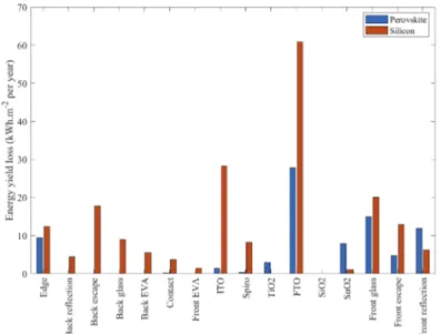
As presented in Fig.11, the main losses are impacting the silicon cell and come from parasitic absorptions in layers of the perovskite cell. This show that further work on semi-transparent perovskite solar cells for tandem applications can be expected to bring significant efficiency gains. FTO and ITO are the two first materials to be tackled for such objective.
Fig. 11.Energy yield reduction through optical losses in both sub-cells. Realistic conditions
in Denver with a sand albedo are used. Perovskite and Silicon refers to losses occurring respectively above or below perovskite bandgap.
The results of Fig.11are obtained with climatic conditions in Denver with a sand albedo. The specificity of back light management optimization, depending on albedo, is perceptible through analyzing back escape. The module optimized to favor back light penetration (Fig.6(d)) performs better than the module aiming at reducing escape of light coming from the front (Fig.6(b)): it losses 17.8 kWh.m−2instead of 19.3 kWh.m−2. In low albedo condition the situation is reversed:
device (d) and (b) loose respectively 14.2 and 11.5 kWh.m−2per year as back escape.
This confirms that the best light management has to favor back light penetration in such conditions (strong albedo). Nevertheless, the small difference shows also that such aspect is small, allowing standardization of bifacial tandem modules.
6. Conclusion
Optical modeling combining ray-tracing and transfer matrix methods allows investigating four-terminal perovskite on silicon tandem modules. Hence, interfaces of the device are examined and
improved in order to enhance light penetration in cells absorbers. In this work we have shown that back light management is necessary in order to take advantage of albedo and surrounding conditions in perovskite/silicon tandem bifacial module. More interestingly, when considering bifacial modules, advantages of backside silicon texture are influenced by trade-off between light management of front and back illuminations, making the best device structure dependent on illumination conditions, especially albedo. Spectra modeling in realistic conditions is therefore done by combining representative meteorological data and SMARTS2 spectra modeling tool, in order to validate the previous design improvements. Three locations are used to give an overview of the various climates under which solar modules operate. Not only current photogeneration but also energy production is estimated to offer a comparison of improved devices in these conditions. Results confirm first modeling conclusions under AM1.5g spectrum: back light management leads to clear gain in energy yield. The dependence of best back designs on location is confirmed, but advantages between module designs remain of low order. Furthermore, both optimized designs for the back side show comparable advantages at all locations.
This is a good sign for future standardization of perovskite-silicon bifacial tandems, in addition to the advantage of four terminal over two terminal modules, being more flexible to albedo conditions without the need of current matching. It appears that taking advantage of diffused light by having good reflecting soil materials behind the module could improve energy production by more than 21% in a location where incoming irradiance is naturally low and diffuse, namely in temperate-cold climates. This gives elements for the back light management optimization of four-terminal tandem module taking into account surroundings, albedo conditions and spectral effects.
Appendix
Parameters for optical modeling
Table 3. Layer thicknesses and refractive indices used in optical simulations.
Material Thickness Optical indices
Glass 3 mm [17] SnO2 8 nm [17] SiO2 40 nm [17] FTO 500 nm [17] TiO2 40 nm [17] Mesoporous TiO2 100 nm [17] Perovskite 600 nm [17] Spiro 270 nm [17] ITO 280 nm [17]
Index Matching layer (IML) 450 µm [32]
SiNx 80 nm [33]
Silicon 170 µm [34] Al2O3 5 nm [35]
SiNx 180 nm [33]
Details on the random nature of pyramids used as texture
When textured interfaces are simulated, upright pyramids with random surface morphologies are considered. When a ray leaves the parallelepiped constituting the pyramid’s unit cell, a random
location on the adjacent unit cell is selected, and then the ray propagates into the neighboring unit cell. This is equivalent to randomly translating the adjacent unit cell in the x (or y) and z directions.
Details on front and back illuminations
In so far as front and back side illuminations are not linked in term of coherency front and back illumination can be considered separately. For each illumination, each ray is defined by some parameters (wavelength, intensity, direction, and source). For back illumination the source is located below the module. After propagating through the layers, the photogeneration, reflection, transmission, and parasitic absorption are saved for each ray (being either front or back illumination), summed, and averaged to give the results of the ray packet. This is repeated for several ray packets. The final gains and losses are then obtained by averaging large number of rays, which make the Monte Carlo simulation converge to the physical model.
In the case of simulation with front and back side illuminations, rays coming from both sides are considered independently and summed altogether. The power of all illumination sources accounts for front and back side.
Details on contacts considered
Metal grid contacts on the silicon sub-cell are included in optical simulations considering ‘PseudoRectangular’ sections (rectangle with the two up corners rounded) and a classical pattern is considered. Optical indices of the contact material are considered to fully resolve reflections at their surface, and simulate the shading effect for instance. Optical properties of the area between the finger contacts are also implemented. In the case of the perovskite sub-cell, transparent and conducting oxides are considered and parasitic absorptions due to these layers are computed. Results of optical modeling
Fig. 12. Absorption simulated in modules. Currents are also shown in order to help
analyzing losses at the back of the silicon cell for the monofacial (left) and bifacial module (right). In this case incoming light only comes from the front.
Results of realistic conditions modeling
The spectra presented in Fig.14result from a year-average each hour. This shows the evolution of light along a day. As it is presented in the literature [37], the absorbed spectra shifts towards short wavelength along the morning (independently from the global intensity increase) The longer path through the atmosphere when the sun is low results in more Rayleigh scattering (which impacts more short wavelengths than longer wavelengths). The normal direct irradiance (see Fig.14(a))
Fig. 13.Simulated photogenerated currents in the bifacial tandem (left is structure (d) and
right structure (b)) module as a function of back glass texture pyramid base angle and ARC thickness. The device is illuminated by direct AM1.5 g spectrum at the front and diffuse light coming from sand (left) and grass (right) albedo.
Table 4. Site characteristics for Las Vegas, Denver and Seattle. Annual irradiances, average temperature, and pressure calculated from TMY3 data, average precipitation and humidity from
NOAA [36] data.
Las Vegas Denver Seattle Latitude 36.083° 39.833° 47.467 °
Altitude 648 m 1650 m 122 m
Annual normal direct irradiance 2592 kWh/m2 1978 kWh/m2 1158 kWh/m2
Annual horizontal diffuse irradiance 520 kWh/m2 556 kWh/m2 584 kWh/m2
Average precipitation 10.65 cm 41.15 cm 95.02 cm Average temperature 19.8 °C 10.9 °C 6.3 °C Average pressure 988 mbar 835 mbar 1001 mbar
Average humidity 30% 50% 74%
is the most impacted. The diffuse spectrum perceived on the front side (see Fig.14(b)), mainly resulting from Rayleigh scattering is thus very rich in short wavelength photons.
Fig. 14. Denver averaged irradiation spectra computed over a year, grouped by hour of
the day. Direct normal irradiance (A), diffuse irradiance on a tilted surface (B) and diffuse irradiance reflected by grass albedo (C) are modelled. Spectra are all normalized to a broadband power of 1 W.m−2in order to compare their shapes.
Funding
Programme d’Investissements d’Avenir (ANR-IEED-002-01).
Disclosures
The authors declare that there are no conflicts of interest related to this article.
References
1. A. De Vos, “Detailed balance limit of the efficiency of tandem solar cells,”J. Phys. D: Appl. Phys.13(5), 839–846
(1980).
2. W. Shockley and H. J. Queisser, “Detailed balance limit of efficiency of p-n junction solar cells,”J. Appl. Phys.32(3),
510–519 (1961).
3. M. Jaysankar, M. Filipiča, B. Zielinskia, R. Schmagerc, W. Songa, W. Qiu, U. W. Paetzoldc, T. Aernoutsa, M. Debucquoya, R. Gehlhaara, and J. Poortmansa, “Perovskite-silicon tandem solar modules with optimised light harvesting,”Energy Environ. Sci.11(6), 1489–1498 (2018).
4. U. W. Paetzold, R. Gehlhaar, J. G. Tait, W. Qiu, J. Bastos, M. Debucquoy, M. Jaysankar, T. Aernouts, and J. Poortmans, “Optical loss analyses and energy yield modelling of perovskite/silicon multijunction solar cells,” Opt. Sol. Energy SoW2C.4 (2016).
5. B. C. Duck, R. B. Dunbar, O. Lee, K. F. Anderson, T. W. Jones, G. J. Wilson, and C. J. Fell, “Energy yield potential of perovskite-silicon tandem devices,” in 2017 IEEE 44th Photovoltaic Specialist Conference, PVSC 2017 (2017), pp. 1–6.
6. M. Filipič, P. Löper, B. Niesen, S. De Wolf, J. Krč, C. Ballif, and M. Topič, “CH3NH3PbI3 perovskite / silicon tandem solar cells: characterization based optical simulations,”Opt. Express23(7), A263–278 (2015).
7. M. Jošt, E. Köhnen, A. Morales Vilches, B. Lipovšek, K. Jäger, B. Macco, A. Al-Ashouri, J. Krc, L. Korte, B. Rech, R. Schlatmann, M. Topic, B. Stannowski, and S. Albrecht, “Textured interfaces in monolithic perovskite/silicon tandem solar cells: Advanced light management for improved efficiency and energy yield,”Energy Environ. Sci.
11(12), 3511–3523 (2018).
8. R. Santbergen, T. Meguro, T. Suezaki, G. Koizumi, K. Yamamoto, and M. Zeman, “GenPro4 Optical Model for Solar Cell Simulation and Its Application to Multijunction Solar Cells,”IEEE J. Photovoltaics7(3), 919–926 (2017).
9. R. Santbergen, R. Mishima, T. Meguro, M. Hino, H. Uzu, J. Blanker, K. Yamamoto, and M. Zeman, “Minimizing optical losses in monolithic perovskite / c-Si tandem solar cells with a flat top cell,”Opt. Express24(18), A1288–1299
(2016).
10. N. Tucher, O. Höhn, J. N. Murthy, J. C. Martinez, M. Steiner, A. Armbruster, E. Lorenz, B. Bläsi, and J. C. Goldschmidt, “Energy yield analysis of textured perovskite silicon tandem solar cells and modules,”Opt. Express
27(20), A1419–A1430 (2019).
11. H. Shen, D. Walter, Y. Wu, K. C. Fong, D. A. Jacobs, T. Duong, J. Peng, K. Weber, T. P. White, and K. R. Catchpole, “Monolithic Perovskite/Si Tandem Solar Cells: Pathways to Over 30% Efficiency,”Adv. Energy Mater.10, 1902840
(2020).
12. R. Asadpour, R. V. K. Chavali, M. Ryyan Khan, and M. A. Alam, “Bifacial Si heterojunction-perovskite organic-inorganic tandem to produce highly efficient (ηT*∼33%) solar cell,”Appl. Phys. Lett.106(24), 243902 (2015).
13. S. Iqbal, K. Riaz, H. Imran, Y. H. Khattak, F. Baig, and Z. Ahmad, “Computational modelling of monolithically stacked perovskite/silicon tandem solar cells using monofacial and bifacial designs,”Optik206, 163427 (2020).
14. R. Schmager, M. Langenhorst, J. Lehr, U. Lemmer, B. S. Richards, and U. W. Paetzold, “Methodology of energy yield modelling of perovskite-based multi-junction photovoltaics,”Opt. Express27(8), A507–A523 (2019).
15. J. Lehr, M. Langenhorst, R. Schmager, F. Gota, S. Kirner, U. Lemmer, B. S. Richards, C. Case, and U. W. Paetzold, “Energy yield of bifacial textured perovskite/silicon tandem photovoltaic modules,”Sol. Energy Mater. Sol. Cells
208, 110367 (2020).
16. “PV Lighthouse: SunSolveTM,https://www.pvlighthouse.com.au,”.
17. E. Raoult, R. Bodeux, S. Jutteau, S. Rives, A. Yaiche, D. Coutancier, J. Rousset, and S. Collin, “Optical characterizations and modelling of semi-transparent perovskite solar cells for tandem applications,” in 36th European
Photovoltaic Solar Energy Conference and Exhibition(2019), pp. 757–763.
18. S. Wilcox and W. Marion, Users Manual for TMY3 Data Sets (National Renewable Energy Laboratory Golden, CO, 2008).
19. C. A. Gueymard, “Parameterized transmittance model for direct beam and circumsolar spectral irradiance,”Sol. Energy71(5), 325–346 (2001).
20. M. A. Anoma, D. Jacob, B. C. Bourne, J. A. Scholl, D. M. Riley, and C. W. Hansen, “View Factor Model and Validation for Bifacial PV and Diffuse Shade on Single-Axis Trackers,” in 44th IEEE Photovoltaic Specialist
Conference(2017), pp. 1549–1554.
21. W. S. Yang, B. W. Park, E. H. Jung, N. J. Jeon, Y. C. Kim, D. U. Lee, S. S. Shin, J. Seo, E. K. Kim, J. H. Noh, and S. Il Seok, “Iodide management in formamidinium-lead-halide-based perovskite layers for efficient solar cells,”Science
356(6345), 1376–1379 (2017).
22. M. H. Futscher and B. Ehrler, “Modeling the Performance Limitations and Prospects of Perovskite/Si Tandem Solar Cells under Realistic Operating Conditions,”ACS Energy Lett.2(9), 2089–2095 (2017).
23. D. Faiman, “Assessing the Outdoor Operating Temperature of Photovoltaic Modules,”Prog. Photovoltaics16(4),
307–315 (2008).
24. A. M. Gracia-Amillo, G. Bardizza, E. Salis, T. Huld, and E. D. Dunlop, “Energy-based metric for analysis of organic PV devices in comparison with conventional industrial technologies,”Renewable Sustainable Energy Rev.93, 76–89
(2018).
25. M. Jošt, B. Lipovšek, B. Glažar, A. Al-Ashouri, K. Brecl, G. Matič, A. Magomedov, V. Getautis, M. Topič, and S. Albrecht, “Perovskite Solar Cells go Outdoors: Field Testing and Temperature Effects on Energy Yield,”Adv. Energy Mater.10(25), 2000454 (2020).
26. BISOL, “BISOL Premium series (monocrystalline),”https://www2.bisol.com/images/Datasheets/EN/BISOLProduct Specification BMO_EN.pdf.
27. U. A. Yusufoglu, T. H. Lee, T. M. Pletzer, A. Halm, L. J. Koduvelikulathu, C. Comparotto, R. Kopecek, and H. Kurz, “Simulation of energy production by bifacial modules with revision of ground reflection,”Energy Procedia55,
389–395 (2014).
28. C. E. Valdivia, C. T. Li, A. Russel, J. E. Haysom, R. Li, D. Lekx, M. M. Sepeher, D. Henes, K. Hinzer, and H. P. Schriemer, “Bifacial Photovoltaic Module Energy Yield Calculation and Analysis,” in 2017 IEEE 44th Photovoltaic
Specialist Conference(2017), pp. 1094–1099.
29. M. Jošt, S. Albrecht, L. Kegelmann, C. M. Wolff, F. Lang, B. Lipovšek, J. Krč, L. Korte, D. Neher, B. Rech, and M. Topič, “Efficient Light Management by Textured Nanoimprinted Layers for Perovskite Solar Cells,”ACS Photonics
4(5), 1232–1239 (2017).
30. S. C. Baker-Finch and K. R. McIntosh, “Reflection distributions of textured monocrystalline silicon: implications for silicon solar cells,”Prog. Photovoltaics21, 960–971 (2012).
31. S. Manzoor, Z. J. Yu, Z. Yang, J. Huang, and Z. C. Holman, “Efficient light management in narrow-bandgap perovskite solar cells,” 0852–0854 (2020).
32. M. R. Vogt, H. Holst, H. Schulte-Huxel, S. Blankemeyer, R. Witteck, D. Hinken, M. Winter, B. Min, C. Schinke, I. Ahrens, M. Köntges, K. Bothe, and R. Brendel, “Optical Constants of UV Transparent EVA and the Impact on the PV Module Output Power under Realistic Irradiation,”Energy Procedia92, 523–530 (2016).
33. K. Luke, Y. Okawachi, M. R. E. Lamont, A. L. Gaeta, and M. Lipson, “Broadband mid-infrared frequency comb generation in a Si3N4 microresonator,”Opt. Lett.40(21), 4823–4826 (2015).
34. C. Schinke, P. Christian Peest, J. Schmidt, R. Brendel, K. Bothe, M. R. Vogt, I. Kröger, S. Winter, A. Schirmacher, S. Lim, H. T. Nguyen, and D. Macdonald, “Uncertainty analysis for the coefficient of band-to-band absorption of crystalline silicon,”AIP Adv.5(6), 067168 (2015).
35. P. Kumar, M. K. Wiedmann, C. H. Winter, and I. Avrutsky, “Optical properties of Al2O3 thin films grown by atomic layer deposition,”Appl. Opt.48(28), 5407–5412 (2009).
36. NCEI and NOAA, “Climate data online,”https://www.ncdc.noaa.gov/cdo-web/.
37. O. Dupré, B. Niesen, S. De Wolf, and C. Ballif, “Field Performance versus Standard Test Condition Efficiency of Tandem Solar Cells and the Singular Case of Perovskites/Silicon Devices,”J. Phys. Chem. Lett.9(2), 446–458 (2018).