O
pen
A
rchive
T
OULOUSE
A
rchive
O
uverte (
OATAO
)
OATAO is an open access repository that collects the work of Toulouse researchers and
makes it freely available over the web where possible.
This is an author-deposited version published in :
http://oatao.univ-toulouse.fr/
Eprints ID : 12409
The contribution was presented at SMSV 2012 :
http://www.icteri.org/page/icteri-2012
To cite this version :
Djeddai, Selma and Mezghiche, Mohamed and Strecker, Martin
A case study in combining formal verification and model-driven engineering. (2013)
In: International Workshop on Algebraic, Logical, and Algorithmic Methods of
System Modeling, Specification and Verification (SMSV 2012) in : 8th International
Conference on ICT in Education, Research, and Industrial Applications - ICTERI
2012, 6 June 2012 - 10 June 2012 (Kherson, Ukraine).
Any correspondance concerning this service should be sent to the repository
administrator:
[email protected]
A Case Study in Combining Formal Verification
and Model-Driven Engineering
⋆Selma Djeddai1, Mohamed Mezghiche2, and Martin Strecker1
1 IRIT (Institut de Recherche en Informatique de Toulouse)
Universit´e de Toulouse Toulouse, France
2 LIMOSE, Universit´e de Boumerd`es
Facult´e des Sciences Boumerd`es, Algeria
Abstract. Formal methods are increasingly used in software engineer-ing. They offer a formal frame that guarantees the correctness of devel-opments. However, they use complex notations that might be difficult to understand for unaccustomed users. It thus becomes interesting to formally specify the core components of a language, implement a prov-ably correct development, and manipulate its components in a graphi-cal/textual editor.
This paper constitutes a first step towards using Model Driven Engineer-ing (MDE) technology in an interactive proof development. It presents a transformation process from functional data structures, commonly used in proof assistants, to Ecore Models. The transformation is based on an MDE methodology. The resulting meta-models are used to generate graphical or textual editors. We will take an example to illustrate our approach: a simple domain specific language. This guiding example is a Java-like language enriched with assertions.
Keywords: Model Driven Engineering; Model Transformation; Formal Meth-ods; Verification
1
Introduction
Domain Specific Languages (DSL) have conquered many different aspects of computer science. They are used in different fields such as aerospace, web-services, multi-media, etc. [1]. Certain DSLs define their semantics in natural languages. However, even though these tend to be quite easy to understand, they usually suffer from incompleteness in some cases and ambiguity in others. Therefore, there emerges a need for defining the formal semantics of DSLs in a mathematically founded framework using proof assistants. Such a phase consists in defining the abstract syntax of a DSL and then grafting a semantics on top of it, using well-understood mechanisms like structural recursion or inductive
relations. Such a semantics is often not executable, but other elements of a for-mal development are, such as compilers or static analyses whose correctness is proved on the basis of the formal semantics.
Interactive proof assistants such as Coq [2] or Isabelle [3] often use paradigms stemming from functional programming (type systems, function definitions), but they are as such not a programming language. It is however possible to export the formal development to programming languages such as Caml [4] or Scala [5]. A formally verified compiler, for example, can therefore be effectively executed in a standard programming language.
In order to improve the user interface for interacting with a DSL, we aim at a textual or graphical concrete syntax as provided, for example, by the Eclipse Xtext or GMF environments. Frequent changes of the DSL during the design phase make it necessary to adapt this interface easily and to re-generate it au-tomatically, as far as possible.
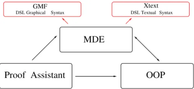
Proof DSL Graphical Syntax GMF Xtext Syntax DSL Textual Assistant OOP MDE
Fig. 1.Meta-modeling(MM), Verification environment and OO languages
This paper studies the interplay of these formalisms (see Figure1), and thus constitutes a first step towards using Model Driven Engineering (MDE) [6,7] technology in an interactive proof development. The guiding example (see Sec-tion3) is a Java-like language enriched with assertions developed by ourselves for which no off-the-shelf definition exists. This “meta-model” (in MDE par-lance) is sufficiently complex to illustrate the method and to be a case study of realistic size for a DSL. However, its formal model can be entirely defined as an inductive datatype (and this is so for most formally defined languages). In this case study, we can therefore not demonstrate some aspects of our work, such as the translation of genuine graph structures that go beyond instances of inductive data types.
Section 2 constitutes the technical core of the article; it describes a transla-tion from data models in the functransla-tional programming world, used in verificatransla-tion environments, to meta models in Ecore: the core language of the Eclipse Mod-eling Framework. We illustrate the methodology in Section3 with a case study. In Section 4 we compare our work to other approaches, before concluding in Section5 with perspectives of further work.
2
From Datatypes to Meta-Models
In this part, we present in detail the translation process from functional data types to meta-models. We start in Section 2.1 by giving an overview of our methodology, then we introduce the source and the target of the transformation in Sections 2.2 and 2.3 respectively. The essence of the translation is further developed in Section2.4.
2.1 Methodology
Model Driven Engineering (MDE) is a software development methodology where the ()models are the central elements in the development process. A meta-model defines the elements of a language. The instances of theses elements are used to construct a model of the language. A model transformation is defined by a mapping from elements of the source meta-model to those of the target meta-model. Consequently, each model conforms to the source meta-model can be automatically translated to an instance model of the target meta-model. The Object Management Group (OMG) [8] defined the Model Driven Architecture (MDA) standard [9], as specific incarnation of the MDE.
We apply this method in order to define a generic transformation process from datatypes (used in functional programming) to Ecore models. Figure2shows an overview of our approach. Using an EBNF representation of the datatype defini-tion grammar [3], we derive a meta-model of datatypes. This meta-model is the source meta-model of our transformation. We also define a subset of the Ecore meta-model [10] to be the target meta-model. In order to perform the transfor-mation, we defined a set of transformation rules (detailed in Section 2.4) that maps components of the meta-model of datatypes to those of Ecore Meta-model. These rules have been implemented in the application presented in Section3.2.
Meta−Model Datatype Functional Ecore Datatype To <<Implements>> Grammar of a Datatype’s EBNF representation <<ConformsTo>> Transformation Rules Meta−Model Ecore Model Datatype <<ConformsTo>> Ecore Model <<ConformsTo>> Datatype Definition
2.2 Source Meta-Model : The Datatype Meta-Model
Functional programming supplies us with a rich way to describe data structures. However, since some features are not supported by Ecore, we have only defined a subset, that contains the essential elements composing datatypes. Figure 3 depicts the datatype metamodel that is constructed from a subset of datatype’s declarations grammar [3].
A Module may contain several Type Definitions. Each Type Definition has a Type Constructor. It corresponds to the data types’ name. It is also composed of at least one Constructor Declaration. These declarations are used to express variant types. Type declarations have names, it is the name of a particular type case. It takes as argument some (optional) type expressions which can either represent a Primitive Type (int, bool, float, etc.) or also a data type defined previously in the module. The list option is used to represent lists in functional programming. The type option feature describes the presence or the absence of a value. The ref option is used for references (pointers).
We enriched the type definition grammar with a new element named Ac-cessor. It is a function introduced by a special annotation (*@accessor*). It allows to assign a name to a special field of the type declaration. This element is essential for the transformation process, its absence would lead to nameless structural features.
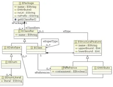
2.3 Target Meta-Model: The Ecore Meta-Model
Our target metamodel is a subset of the Ecore metamodel. Ecore is the core language of Eclipse Modeling Framework (EMF) [11]. It allows to build Java ap-plications based on model definitions. It unifies three technologies: Java, XML and UML. Actually, it is possible to describe a model in one of the three tech-nologies and generate it in the other two. It also allows to develop and integrate Eclipse plug-ins.
The Meta Object Facility (MOF) standardized by the OMG defines a subset of UML class diagram [12]. It represents the Meta-Meta-Model of UML. Ecore is comparable to MOF but simpler. They are similar in their ability to specify classes, structural and behavioral features, inheritance and packages.
Fig. 4.Simplified subset of the Ecore Meta-model
Figure 4 represents a subset of the Ecore language. This subset contains essentially the elements that are needed for the transformation process. Its main components are:
– The EPackage is the root element in serialized Ecore models. It encompasses EClasses and EDataTypes.
– The EClass component represents classes in Ecore. It describes the structure of objects. It contains EAttributes and EOperations.
– The EDataType component represents the types of EAttributes, either pre-defined (types: Integer, Boolean, Float, etc.) or pre-defined by the user. There is a special datatype to represent enumerated types EEnum, each enumeration is called EEnumLiteral.
– EReferences is comparable to the UML Association link. It defines the kinds of the objects that can be linked together. The containment feature is a Boolean value that makes a stronger type of relations. When it is set to true, it represents a whole/part relationship known as “by-value aggregation” in UML.
2.4 From Datatypes to Meta-Models
The transformation method is from functional datatypes to Ecore meta-models. To precisely define transformation rules, the transformation method is presented in a formal notation by the Tr() function. In each case we start by an informal description, then we present it formally and finally we show an effective exemple.
T r : DataT ypes −→ Ecore M eta-model
The following translation functions are given for a concrete syntax in the style of Caml [4]. Since most functional languages (including the language of proof assistants) have great similarities, the concrete syntax can be mapped to different functional languages.
Rule DatatypeToEClass When the datatype is formed of only one construc-tor, it is translated to an EClass. The EClass name is the name of the type constructor. T r(tpConstr = cn t1...tn) = createEClass(); setN ame(tpConstr); T rtype(acci, ti) / 1 ≤ i ≤ n Example: datatypetpConstr =
Cn of int ∗ string ∗ ...∗ bool
Rule DatatypeToEEnum Datatypes composed only of constructors (without typexpr s) are translated to EEnums which are usually employed to model enu-merated types in Ecore. There, each constructor from the datatype model is translated into an EEnumLiteral.
T r(tpConstr = cn1|...|cnp) = createEEnum(); setN ame(tpConstr); T rconstrN m(cni) / 1 ≤ i ≤ p T rconstrN m(cni) = EEnumLiteral(cni) / 1 ≤ i ≤ p Example: datatypetpConstr = Cn1 |Cn2 |... | CnN
Rule DatatypeToEClasses When constructor declarations are composed of more than one constructor declaration containing type expressions: a first EClass is created to represent the type constructor (tpConstr ). Then, for each construc-tor, an EClass is created too, and inherits from the tpConstr one.
T r(tpConstr = cd1|...|cdn) = createEClass();
setN ame(tpConstr); T rdecl(cdi)
/ 1 ≤ i ≤ n T rdecl: ConstructorDeclaration −→ EClass
T rdecl(cnit1...tm) = createEClass();
setN ame(cni);
setSuperT ype (EClass(tpConstr)); T rtype(accj, tj) / 1 ≤ j ≤ m Example: datatypetpConstr = Cn1 of string |Cn2 of int |... |CnN of bool
Rule PrimitivTypeToEAttribute If a type expression is formed of a prim-itive type, the translation function generates a new EAttribute. The name of this EAttribute is the name of its corresponding accessor, and its type is the EMF representation of the the primitive type : EInt for int, EBoolean for bool, EStringfor string, etc.
T rtype: (accessor, type) −→ EStructualF eature
T rtype(acc, primT p) = createEAtrribute();
setN ame(acc);
setT ype(primT pEM F);
Example:
datatypetpConstr =
Cn of int ∗ string ∗ ...∗ bool
Rule TypeToEReference When a type expression contains a type which is not a primitive type, the latter has to be previously defined in the Isabelle theory. Then, a containment link is created between the current EClass and the EClass referenced by type constructor, and the multiplicity is set to 1.
T rtype: (accessor, type) −→ EStructualF eature
T rtype(acc, tpConstr) = createERef erence();
setN ame(acc); setT ype (tp constr); setContainment (true); setLowerBound(1); setU pperBound(1);
Example:
datatypetpConstr = Cn oftpConstr2
Rule TypeOptionToMultiplicity The type expressions can also appear in the form of a type list. In this case the multiplicity is set to 0...*. The type expression type option is used to express whether a value is present or not. It returns None, if it is absent and Some value, if it is present. This is modeled by changing the cardinality to 0...1.
T rtype: (accessor, type) −→ EStructualF eature
T rtype(acc, t list) = T rtype(acc, t)
setLowerBound(0); setU pperBound(∗); T rtype(acc, t option) = T rtype(acc, t)
setLowerBound(0); setU pperBound(1);
Example:
datatypetpConstr =
Cn oftpConstr2 list
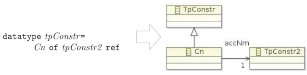
The last case that we deal with, is type ref which is used to represent point-ers. It is translated to references without containments.
T rtype(acc, t ref) = T rtype(acc, t)
Example:
datatypetpConstr =
Cn of tpConstr2 ref
3
Case Study
In this section, we apply the method presented in Section2on a detailed example that consist of a Domain Specific Language. We start by the DSL definition, then we show the architecture of the application before finishing with the effective results of the transformation.
3.1 Presentation of the Case Study
We are currently working on a real-time dialect of the Java language allowing us to carry out specific static analyses of Java programs. We only sketch this language here; details are described in [13]. This language is not a genuine subset of Java, since we have added annotations characterizing timing behavior of pro-gram parts that are inserted in particular comments into the propro-gram. Neither is the language a superset of Java, because we have to impose syntactic restric-tions on the shape of the program, and also static restricrestric-tions on the number of objects that are allocated.
All this made us opt for writing our own syntax analysis, which is integrated into the Eclipse Xtext environment [14]. After syntax analysis and verification of the above-mentioned static restrictions, the program together with its timing annotations is translated to Timed Automata (TA) for model checking. The language is currently not entirely stable and will be modified while we refine and improve the translation from Java to TA, and while the formal model evolves.
The formal aspect comes into play at the following point: We are currently developing a real-time semantics of Java in the proof assistant Isabelle, based on an execution semantics using inductive relations. Performing the translation for the whole language description would generate a huge metamodel that couldn’t be presented in the paper. We thus choose to present a only an excerpt of it, corresponding to a method definition.
Figure6shows the datatype definitions in the Isabelle proof assistant, where a method definition is composed of a method declaration, a list of variables, and statements. Each method declaration has an access modifier that specifies its kind. It also has a type, a name, and some variable declarations. The stmt datatype describes the statements allowed in the method body: Assignments,
Conditions, Sequence of statements, Return and the annotation statement (for timing annotations). In this example we use Booleans, integers, strings for types and values.
3.2 Implementation: DatatypesToEcore
Our approach is implemented using the Eclipse environment which includes among others
– Eclipse Modeling Framework (EMF) [11]: a framework for modeling and code generation that builds tools and applications based on data models. – Eclipse Modeling Project (EMP) [10]: a framework allowing the
manipula-tion of DSLs by defining their (textual/graphical) concrete syntax based on a corresponding metamodel.
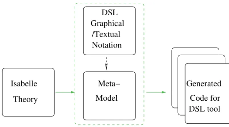
Figure5shows the architecture of our application. There, green arrows represent model transformations or code generation. The base element is an Isabelle theory where both of the datatypes and the properties to be checked are defined. The corresponding meta-model is generated using the translation function described in Section 2.4. Starting from a generated Ecore meta-model, we use the Xtext tool to define a textual concrete syntax. First, Xtext builds an EBNF grammar depending on the structure of the metamodel. The grammar is then adapted using the right key words of the language, yielding a textual editor as an Eclipse plug-in. Code for Generated DSL tool Theory Isabelle DSL Graphical /Textual Notation Model Meta−
Fig. 5.Datatype To Ecore implementation architecture
3.3 Applying the Transformation
Figure6shows a datatype taken form the Isabelle theory where the verifications were performed. Due to lack of space we do not present them in the paper.
This part of the theory was given as input to the implementation of our trans-lation rules presented in Section 2.4. The resulting Ecore diagram is presented in Figure7.
As it is shown on the figure, data type definitions built only of type con-structors (Tp, AccModifier, Binop, Binding) are treated as enumerations in the metamodel. Whereas Datatype MethodDecl composed of only one constructor derive a single class. As for type expressions that represent list of types (like ac-cModifier list in varDecl ), they generate a structural feature in the corresponding class and their multiplicities are set to (0...*). The result of type definitions con-taining more than one constructor and at least a type expression (stmt and expr ) is modeled as a number of classes inheriting from a main one. Finally, the trans-lation of the int, bool and string types is straightforward. They are translated to respectively EInt, EBoolean and EString.
datatype binop = BArith| BCompar| BLogic datatype value = BoolV bool
|IntV int |StringV string |V oidV
datatype binding= Local| Global datatype var = V ar binding string datatype expr = Const value
|V arE var
|BinOperation binop expr expr datatype tp = BoolT | IntT | V oidT | StringT datatype stmt = Assign var expr
|Seq stmt stmt |Cond expr stmt stmt |Return expr
|AnnotStmt int stmt
datatype accM odif ier=
P ublic|P rivate |Abstract|Static |P rotected |Synchronized datatype varDecl=
V arDecl(accM odif ier list) tp int datatype methodDecl=
M ethodDecl(accM odif ier list) tp string (varDecl list) datatype methodDef n=
M ethodDef n methodDecl(varDecl list) stmt Fig. 6. Datatypes in Isabelle
Fig. 7.Resulting Ecore Diagram after Transformation
4
Related Work
EMF models are comparable to Unified Modeling Language Class diagrams. For this fact we are interested in the mappings from other formal languages to UML Class diagrams. Some research is dedicated to establishing the link between these two formalisms. We cite the work of Idani & al. that consists of a generic trans-formation of UML models to B constructs [15] and vice-versa [16]. The authors propose a metamodel-based transformation method based on defining a set of structural and semantic mappings from UML to B (a formal method that allows to construct a program by successive refinement, using abstract specifications).
Similarly, there is an MDE based transformation approach for generating Alloy (a textual modeling language based on first order logic) specifications from UML class diagrams and backwards [17], [18].
Delahaye & al. describe in [19] a formal and sound framework for transform-ing Focal specification into UML models.
These methods enable to generate UML component from a formal descrip-tion but their formal representadescrip-tion is significantly different from our needs: functional data structures.
Also, graph transformation tools [20,21] permit to define source and target metamodels all along with a set of transformation rules and use graphical repre-sentations of instance models to ease the transformation process. However, the verification functionality they offer is often limited to syntactic aspects (such as confluence of transformation rules) and does not allow to model deeper seman-tic properties (such as an operational semanseman-tics of a programming language and proofs by bisimulation).
Our approach combines the two views by offering the possibility to define the abstract syntax of a DSL, to run some verifications on the top of it and to generate the corresponding metamodel to graphically document the formal developments. Furthermore, this metamodel can be used to easily generate a textual editor using Xtext facilities.
5
Conclusion
Our work constitutes a first step towards a combination of interactive proof and Model Driven Engineering. We have presented a generic method based on MDE for transforming data type definitions used in proof assistants to class diagrams. The approach is illustrated with the help of a Domain Specific Language developed by ourselves. It is a Java-like language enriched with annotations. Starting from data type definitions, set up for the semantic modeling of the DSL we have been able to generate an EMF meta-model. In addition to its benefits for documenting and visualizing the DSL, it is manipulated in the Eclipse workbench to generate a textual editor as an Eclipse plug-in.
Currently, we are working on extending subset of data type definitions by adding a way to transform parameterized types to generic types in Ecore. And coupling our work with the generation of provably correct object oriented code from proof assistants. Moreover, we intend to work on the opposite side of trans-formation, the possibility to generate data structure definitions from class dia-grams.
References
1. van Deursen, A., Klint, P., Visser, J.: Domain-specific languages: An annotated bibliography. SIGPLAN Notices 35 (2000) 26–36
3. Nipkow, T., Paulson, L., Wenzel, M.: Isabelle/HOL. A Proof Assistant for Higher-Order Logic. Volume 2283 of Lecture Notes in Computer Science. Springer Berlin / Heidelberg (2002)
4. http://caml.inria.fr: Caml programming language website (2012)
5. Martin Odersky et al.: An Overview of the Scala Programming Language. Tech-nical report, EPFL (2007)
6. B´ezivin, J.: Model driven engineering: An emerging technical space. In L¨ammel, R., Saraiva, J., Visser, J., eds.: Generative and Transformational Techniques in Software Engineering. Volume 4143 of Lecture Notes in Computer Science. Springer Berlin / Heidelberg (2006) 36–64
7. Selic, B.: The pragmatics of model-driven development. IEEE Software 20 (2003) 19–25
8. OMG: Meta Object Facility (MOF) Core v. 2.0 Document. (2006)
9. Kleppe, A.G., Warmer, J., Bast, W.: MDA Explained : The Model Driven Archi-tecture : Practice and Promise. Addison-Wesley Longman Publishing Co., Inc., Boston, MA, USA (2003)
10. Gronback, R.C.: Eclipse Modeling Project: A Domain-Specific Language (DSL) Toolkit. Addison-Wesley, Upper Saddle River, NJ (2009)
11. Budinsky, F., Brodsky, S.A., Merks, E.: Eclipse Modeling Framework. Pearson Education (2003)
12. France, R.B., Evans, A., Lano, K., Rumpe, B.: The UML as a formal modeling notation. Computer Standards & Interfaces 19 (1998) 325–334
13. Baklanova, N., Strecker, M., F´eraud, L.: Resource Sharing Conflicts Checking in
Multithreaded Java Programs. Informal Proceedings FAC’12 (2012)
14. Eclipse Community: Tutorials and documentation for Xtext 2.0 (2011) http:
//www.eclipse.org/Xtext/documentation/.
15. Idani, A., Boulanger, J.L., Philippe, L.: A generic process and its tool support towards combining UML and B for safety critical systems. In Hu, G., ed.: CAINE, ISCA (2007) 185–192
16. Idani, A.: UML models engineering from static and dynamic aspects of formal specifications. In Halpin, T.A., Krogstie, J., Nurcan, S., Proper, E., Schmidt, R., Soffer, P., Ukor, R., eds.: BMMDS/EMMSAD. Volume 29 of Lecture Notes in Business Information Processing., Springer (2009) 237–250
17. Shah, S.M.A., Anastasakis, K., Bordbar, B.: From UML to Alloy and back again. In Ghosh, S., ed.: MoDELS Workshops. Volume 6002 of Lecture Notes in Computer Science., Springer (2009) 158–171
18. Anastasakis, K., Bordbar, B., Georg, G., Ray, I.: UML2Alloy: A challenging model transformation. In Engels, G., Opdyke, B., Schmidt, D.C., Weil, F., eds.: MoDELS. Volume 4735 of Lecture Notes in Computer Science., Springer (2007) 436–450 19. Delahaye, D., ´Etienne, J.F., Vigui´e Donzeau-Gouge, V.: A Formal and Sound
Transformation from Focal to UML: An Application to Airport Security Regula-tions. In: UML and Formal Methods (UML&FM). Innovations in Systems and Software Engineering (ISSE) NASA Journal, Kitakyushu-City (Japan), Springer (2008)
20. de Lara, J., Vangheluwe, H.: Using AToM3 as a meta-case tool. In: Proceedings of the 4st International Conference on Enterprise Information Systems (ICEIS), Ciudad Real, Spain (2002) 642–649
21. Ehrig, K., Ermel, C., H¨ansgen, S., Taentzer, G.: Generation of visual editors as Eclipse plug-ins. In: Proceedings of the 20th IEEE/ACM international Conference on Automated software engineering. ASE ’05, New York, NY, USA, ACM (2005) 134–143