This is an author-deposited version published in: http://oatao.univ-toulouse.fr/
Eprints ID: 3600
To cite this document : LIZY-DESTREZ, Stéphanie , LE BUAN, Christophe,
Francillout, Laurent. Analysis of the resilience of the ATV
operations. In : Spaceops
2010, 25-30 April 2010, Huntsville, Alabama
Any correspondence concerning this service should be sent to the repository
administrator:
staff-oatao@inp-toulouse.fr
Analysis of the resilience of the ATV operations
Stéphanie Lizy-Destrez1Institut Supérieur de l’Aéronautique et de l’Espace, Toulouse, France, 31320
Christophe Le Buan2
Altran Sud-Ouest, Blagnac, France, 31700 and
Laurent Francillout3
Centre National d’Etudes Spatiales, Toulouse, France, 31401
The resilience of a system consists in its capability to maintain a safe and satisfactory mission, in its operational environment, while adapting to changing conditions (foreseen or unforeseen events, losses, failures, ….) and mitigating the risk of contingencies. To guarantee the success of the ATV future missions (from ATV2, Johannes Kepler), the operational teams at ATV-CC (ATV Control Center), with the help of the vehicle designers, have built dedicated processes, developed particular tools and set specific advanced training right from the earliest preparation phase. In order to be compliant with strong safety requirements (due to the proximity of and interfaces with the ISS), operational teams have to prepare strategies balancing total automation versus human reaction, or training (at least, one procedure for each foreseen case) versus adaptation. Combining system engineering principles and lesson learnt from ATV Jules Verne mission, the Vehicle Engineers Team (VET) at ATV-CC challenges the improvement of the global system resilience through several means (ground and on-board alarms, specialized procedures, specific displays, …) depending on contingencies level, for next missions. The paper describes the strategies (in term of processes and tools) set up by the Vehicle Engineers Team, in accordance to safety requirements, interfaces with the international partners and ATV-CC rules to ensure the ATV operations.
I. Introduction
.The ATV Jules Verne, as prototype of the first European automated cargo vehicle to deserve the International Space Station (ISS) had to challenge high level success and safety criteria, (particularly during docking at ISS and during re-entry). Consequently, designing such a vehicle was very complex as far as redundancies management, high safety margins, long and complicated validation campaigns were concerned. Nevertheless, despite the vehicle large autonomy, an important part of mission success management relies on ground segment and in particular, on operators in the ATV control centre in Toulouse. Thus, dedicated procedures, corresponding to particular strategies, to conduct the operations, have been implemented to ensure the Jules Verne ATV mission and to adapt the system to any disturbances and unpredictable events.
1 Associate Professor, DMIA (Department of Mathematics, Computer Science and Control Theory), 10, avenue Edouard Belin - BP54032 - 31055 Toulouse Cedex 4 - France.
2 ATV-CC Vehicle Engineer, Altran Sud-Ouest, 4 avenue Didier Daurat - Batiment Centreda 3 - Immeuble Synapse – 31700 Blagnac - France
3 ATV-CC Vehicle Engineers Team Leader, Operations Sub_Directorate, 18, avenue Edouard Belin - BP54032 - 31401 Toulouse Cedex 4 - France
The objective of the present article is to analyze the ATV system resilience, with a focus on operational phase of its life-cycle.
The article falls into three main parts:
• The first paragraph deals with resilience definition. • The second chapter presents the ATV system.
• The third chapter analyses the ATV-CC strategies to transform ATV system from a safe system to a resilient system.
II. What is resilience?
Resilience means the capacity of a system to react to an unpredictable perturbation in its environment and to come back to a nominal functioning state.
There are three main characteristics for resilient systems:
• The capacity to react quickly and efficiently to classical perturbations and threats.
• The capacity to monitor continuously unexpected perturbations and threats and to update monitoring laws.
• The capacity to anticipate environment modifications to come that may impact the system functioning and to prepare system evolutions.
In the following chapters, we will demonstrate why Jules Verne ATV system is resilient. In particular, we will describe the ATV-CC strategies to ensure the mission in a changing environment (debris, ….). The ATV system must be resilient since it has to be compliant with high level safety requirements. Those specifications are very strict since ATV flies in the neighborhood of an inhabited International Space Station.
An example in the case of ATV-CC of the first identified resilient capacity is: perturbations and threats can correspond to on board failure (equipment dysfunction), operational planning changes or ground tools problems. Consequences can be to reschedule the operational activities, to update procedures or to modify Vehicle configuration.
An example in the case of ATV-CC of the third identified resilient capacity is: the environment modifications could happen on ground during launch phase (with a change in the launcher sequence), in orbit with a change of the trajectory because of debris or in attached phase with an unexpected modification of ISS configuration. In that way, ATV-CC operators should analyze in real time the new environment and modify their activities to adapt the global system (Ground segment and Vehicle) to the new external conditions.
III. ATV system presentation
A. ATV Jules Verne mission presentation
As first European cargo vehicle, the Jules Verne ATV mission objectives were to • Deliver gas, fluids and cargo to the ISS
• Perform propulsive support to the ISS attitude and control sub-system while raising the Station orbit • Perform a DAM (Debris Avoidance Maneuver) in case of Debris on ISS orbit
• Dispose Station waste during re-entry
During operational phase, the main steps of ATV mission are: • Pre-launch
• LEOP (Launch and Early Orbit Phase) • Phasing
• Rendez-Vous split into several sub-phases: pre-homing, homing, closing, final approach 1, final approach2
• Docking
• Attached phase with refueling activities, ISS reboosts,… • Undocking
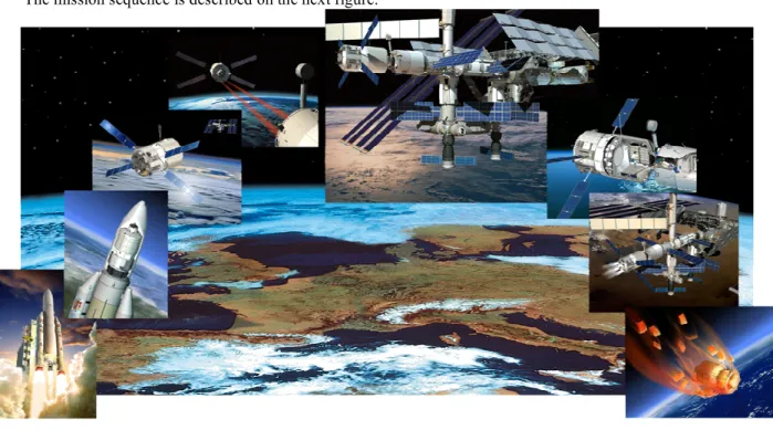
The mission sequence is described on the next figure:
Figure 1: ATV Jules Verne mission
Launched by Ariane 5, the ATV performs few days in free - flight after the end of the LEOP. The entire Jules Verne duration was seven months from launch on the 9th March 2008, to docking on 3rd April 2008, undocking on 5th September 2008 and re-entry on the 29th September 2008.
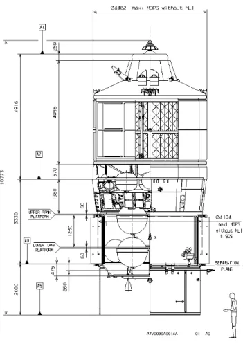
B. ATV vehicle presentation
As compared to any European spacecrafts, the Jules Verne ATV is a giant with its huge dimensions: more then 10 meters length, and up to 4,5 meters in diameter. Composed of two main parts (the ICC, Integrated Cargo Carrier and the service module), it has four x-shape solar arrays with a 22,3 meter span, when deployed, that can provide up to 4,8 kW.
Nevertheless, the main technical challenges are in the vehicle complexity with: • Sub-systems complexity and complex architecture
• FCS (Flight Control System) complexity and redundancy management (GNC, FCM, PFS)
The ATV concept lies in a sophisticated functional architecture, based on Functional Units (composed by hardware and software elements) and Software Units (only composed by software elements).
Some examples of ATV main functions are: flight control, collision avoidance, propulsive support, refueling, power supply….
Some examples of ATV FU are: Communications, GNC measurements, Thermal Control….
Some examples of ATV SU are GNC (Guidance, Navigation and Control), Telemetry and Telecommand,… Specific modes have been designed to correspond with specific function and specific vehicle configuration (depending on the state of the different FU/SU). All those modes and equipment health status are managed by the MVM (Mission and Vehicle Management), on particular FU. Moreover, to improve safety, some activities are automated on-board. For example, the MVM is in charge of the OMP (On-board Mission Plan: sequence of telecommands to be executed), reacts autonomously in case of some on-board alarms rising and performs FDIR.
Moreover, the safety constraints have an important impact on the vehicle design. Actually, some particular FU/SU have been developed to ensure safety, like PFS (Proximity Flight Safety). The main objective of PFS is to prevent from ATV collision with the ISS. The sub-system is able to compute an active CAM (Collision Avoidance Maneuver) to change autonomously the vehicle trajectory and guarantee the ISS safety. Using it own algorithm, the
PFS monitors the other ATV computers and the trajectory. This function is available from phasing to docking and during departure. It is supported by two segregated computers, the MSU, by software, by measurements from the gyrometers and dedicated thrusters.
The following picture presents an overview of the ATV architecture.
Figure 2: ATV architecture
Credits: ESA
The ATV organic architecture is composed by innovative components (in particular sensors used by GNC) and COTS (Commercial, Off-The-Shelf). For example, the DRS (Docking and Refueling Subsystem) uses the Russian docking system (RDS), developed and provided by RSC-E for other space missions.
C. ATV ground segment presentation
The ATV is monitored and commanded from the ground by the ATV-CC, located in CNES at Toulouse (France). The ATV-CC is in charge of the ATV operations and coordinates all ground segment interfaces, in relation with its Russian and American partners.
Figure 3: ATV-CC organisation
ATV-CC interfaces with its partners (MCC-M at Moscow and MCC-H at Houston), with the other European ground segment (COL-CC, ARTEMIS MCF,…) and with Ariane ground segment at Kourou, in French Guiana.
At Toulouse, the ATV operational activities require more than one hundred people. During critical activities, several international teams work at the same time inside the ATV Control Center, with people from ESA, CNES, NASA, Energia, EADS and from many other supplier companies. The ATV-CC is composed by three main teams: the OMT (Operation Managemant Team) , the FCT (Flight Control Team) and the EST (Engineering Support Team). Inside the FCT, the VET is responsible, during the operational phase, for Vehicle configuration and behavior monitoring, for activities up-loading (like maneuvers) and execution monitoring. The VET exchanges with the vehicle through telecommand and telemetry links.
As the VET is the only and ultimate team directly in contact with the vehicle, the resilience capacity of the system depends on VET organization and strategies. That is the reason why, next chapter focus on the Vehicle team activities.
IV. ATV-CC strategies for a resilient system
This paragraph deals with the strategies by ATV-CC and in particular, by VET not only to ensure the Jules Verne mission but also to face to any hazard (perturbations, threats, failures, mistakes…).
The main topics of this paragraph are:
• Preparation and Validation of the procedures • Monitoring strategies
• Training strategies
D. Preparation and Validation of the procedures
A major safety rule that any VET must respect is that: “ no TC shall be sent outside a validated procedure”. As a consequence, each activity (monitoring, maneuvers, equipment wake up, ….) that has to be run during operations, is encapsulated in a procedure. Those procedures, named VCP, are first designed by Jules Verne industrial designers (from EADS-ST at Les Mureaux), and then validated on simulators according to a qualification strategy.
After validation, EADS-ST delivers all those VCP to ATV-CC that has to qualify them in the operational environment. And then, the VCP become FCP.
As there are more then 900 FCP, a qualification strategy has been set up. This strategy, called “prioritization”, is based on “Level of Confidence”, to be achieved by an individual FCP. This Level of Confidence corresponds to a mandatory development/verification/validation/qualification level. It is the result of a combination of four criteria like:
• Occurrence probability,
• Response delay to an event (immediate, some orbits, non-urgent),
• Preparation and qualification procedure complexity (depending on the number of TCs, branching, …. In the procedure),
• Criticality: safety impact on the ISS crew or on the ISS, on the mission (loss of a basic ATV function that prevents the mission to go on), on the vehicle configuration (redundancy loss) or minor impact, For each FCP, a level of confidence is computed thanks to a composition rule from level 1 (the lowest) to level 4 (the highest). For example, a safety critical FCP is level 4, while an ATV configuration FCP is level 2. Actually, the overall level achieved by a FCP is obtained by the highest level among the four criteria assessment.
By consequence, any FCP that is necessarily run (occurrence is 100%), either involved in an immediate reaction (after an urgent alarm), either safety or mission critical, or involved in a MEP (Multi-Element Procedure that implies ATV-CC partners) is a level 4 procedures.
To each level corresponds a validation level that is illustrated on the next table. The four identified validation level are defined as:
• “Produced” means that the procedure has been delivered by EADS-ST and then translated from VCP to FCP by a Vehicle Engineer and verified by the MOIS (Manufacturing and Operations Information System) production tool.
• “Paper reviewed” means that the procedure has been prepared and produced by a Vehicle Engineer and has been verified by another Vehicle Engineer (with a paper version of the procedure, not with simulation means).
• “Simulation” means that the procedure has been produced by a Vehicle Engineer and has been tested in stand-alone configuration on the AGCS (ATV Ground Control Simulator), the ATV test and training platform.
• “OQ/JIS” means that the procedure has been produced and then has been tested in more realistic ground segment environment. It can imply ATV-CC Partners (MMC-M or MMC-H) during JIS or multi-segment rehearsal or involve all ATV-CC teams during OQ.
The following table presents the relationship between level of confidence and qualification expected level.
Levels Produced Paper reviewed Simulation OQ/JIS
Level 1 X
Level 2 X X
Level 3 X X X
Level 4 X X X X
Moreover, as Vehicle Engineers have designed a new classification for the Flight procedures. FCP are then ranked by categories: mission, phases, vehicle and vehicle sub-systems. The FCP nomenclature corresponds to the categories.
Applying this whole strategy on procedure production and validation permits VET to be very confident to its procedures. For example, Vehicle Engineers have designed a new classification (like a tree) for the Flight procedure. FCP are then ranked by categories: mission, phases, vehicle, and vehicle sub-system. That reduces stress and human errors probability during operations. In case of hazards, a VET operator was able to analyze quickly the vehicle configuration and to suggest a contingency procedure (that has been prepared and validated before).
Preparing and validating the procedures increase VET knowledge about the vehicle configuration and its nominal behavior. As a consequence, it increases the VET capacity to anticipate problems or abnormal behavior.
E. Monitoring strategies
evolution of its temperature permits the Vehicle Engineer to detect a problem before the temperature reaches a dangerous limit.
Consequently, during operations preparation phase, VET has set up strategies to accurate tools to ensure monitoring. Those tools are supported by M&C (Monitoring and Control) software functionalities. There are two main kind of monitoring tools: the displays and the Ground Alarms (GAL).
1. Displays conception strategy
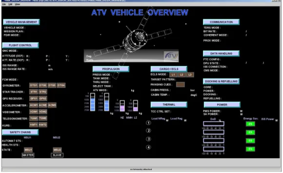
The displays correspond to all graphical user interfaces available on the screen of the M&C used by each Vehicle Engineer. A display example is given on the following figure.
Figure 4: ATV Vehicle overview display
As far as resilience is concerned, the main displays properties are: • Complete • Synthetic • Ergonomic • Structured • Evolving Completeness:
First important assumption that drives displays conception is that any ATV parameter that is downlink in telemetry has to be accessible to the operator. Display can be created in real time, but they have above all been designed, produced and validated before operations. Moreover, there were essential for Vehicle Engineer training.
Synthetic property:
The main objective of a display is to give a rapid synthesis of the current configuration of a specific sub-system or of a mission phase. As the vehicle is a very complex system (see §B), the operators need to have all the critical information at one glance. But, no doubt shall be possible. For example, there is a display that sums up the vehicle configuration with vehicle mode, status of the critical equipments … And there is also a synthetic display for the GNC sub-system and several dedicated displays for Star Tracker parameters.
Ergonomic property:
A color code has been defined and shared with all the ATV-CC actors. So information are quickly observed and analyzed. Some displays can even mix different type of parameter representations: like plots, scales, animated images, labels, …
Structured property:
All the displays have a unique name, and their configuration (evolutions, update, …) are managed. They are classified in a tree structure, organized by mission phase or by sub-system, then by equipment. As a consequence, a Vehicle Engineer looking for a new display to open can find it rapidly in the display tree structure.
Evolving property:
Not only display can be created in real time during operations, but also monitoring ground parameters can be added and computed during operational phases. Those derived parameters, calculated with simple mathematical formulae combining constants and telemetry parameters, permits access to supplementary information on the Vehicle behavior. For example, when an abnormal behavior is forecasted by a Vehicle Engineer, the VET operator is able to compute the parameter evolution and compare it to a limit threshold, so as to anticipate the failure.
Thanks to all those displays properties, VET operator are confident in displayed data. So they can monitor continuously and anticipate the vehicle behavior. Those strategies improve efficiently the resilience of ATV operations activities.
2. Ground alarms conception
Ground alarms are essential for Vehicle monitoring during operational activities. Those alarms are automatic tools implemented on the M&C software, thanks to the system database extraction. Actually, those ground alarms are defined by the Vehicle designers’ team and are discussed with the VET operators so as to all stakeholders requirements are satisfied. Those ground alarms complete the set of Vehicle monitoring activities, in addition to on-board alarms.
Ground alarms are logical expressions comparing instant parameter in telemetry to thresholds or logical values. If the obtained value is out of range, an alarm is raised: data on the screen are flashing and a bell is ringing. As a consequence, ATV-CC operators are instantly advised of the abnormal situation.
Ground alarms are also defined by validity conditions that lead to adapt the monitoring to on-board configuration (Vehicle mode, equipment status….). As a consequence, an alarm is well designed for a particular situation and is not applied in another situation. Synthetic property of ground alarms is improved by using those validity conditions.
Almost the same properties (as for displays) can be defined for ground alarms: Complete, Synthetic, Ergonomic, Structured and Evolving.
Evolving property:
Grounds alarms are also flexible. New ground alarm can be implemented during operational phases, so as to monitor a dedicated parameter, to analyze precisely its evolution and to anticipate dangerous behavior (high temperature, high angle, high speed…).
Synthetic and Ergonomic:
As there are a great amount of telemetry parameters to be monitored, and as the monitoring laws may differ from an operational mode to another one, the number of ground alarms is very high. So, VET operators, with the help of the vehicle designers, have developed a monitoring strategy for those parameters. The ground alarm have been split into three main levels:
• CAUTION • ACTION/urgent • ACTION/low
A “caution” alarm is raised for information. The operators have to do more investigation before acting (applying a specific procedure described in the alarm).
An “action” alarm requires an operator reaction: if the alarm is urgent (reaction time duration has been defined corresponding the mission phases), the TC sending becomes the prior activity of the VET operator, while if it is low, the VET operator can finish the current activities, before applying the required procedure.
A color code has been set-up: orange for CAUTION alarm and RED for ACTION alarm. An in any case, no doubt is possible. Thanks to the information encapsulated in the alarm and available on the displays, a Vehicle
The criticality level for alarms have been according to several criteria, but the highest severity corresponds to, the mission continuation or the vehicle integrity. Lowest levels correspond to further consequences on mission next phases.
For the next ATV generations, four ACTION ground alarms have been identified: urgent/high/medium/low. Reaction delay has been quantified for all of those levels and for two mission phases types (free – flight and attached phases so as to increase the matching between required reactivity and problem diagnostic.
For example, for free * flight phase, the relationship between ACTION ground alarm and required reactivity delay is:
Level Urgent High Medium Low
Reactivity 5 minutes 10 minutes 1 orbit More than 1 orbit
Complete and structured:
Ground alarms are managed through the ATV system database. But, VET has also developed its own down lesson learned database on ground alarm so as to improve the VET knowledge on ATV behavior and to share it among the team members. This database includes all information about a ground alarm when raised, (time, vehicle mode, current operations, value…..).
Moreover this tool is organized with a tree structure (as for displays), each branch corresponding to mission phase or sub-system. Each ground alarm has a unique name. Consequently, a VET operator can search very rapidly in this database to have all required information about that ground alarm.
Nevertheless, the main difficulty with alarm concerns the false alarms. Actually, sometimes, it is very difficult to define a simple logical expression to monitor data evolution. Consequently, some laws may depend on vehicle configuration. But, the vehicle is so complex, that there are less vehicle modes provided in telemetry then vehicle possible configuration (depending on all sub-systems states….). Thus, an expression that must be true in one vehicle configuration, but not in the next one can lead to raise an alarm, since only the vehicle mode is delivered in TM.
The main way to avoid such an ambiguous situation is to train very precisely the VET operators to distinguish true and false alarm, depending on the current operations. In any case, even in a well-known false alarm situation, the VET operators have to confirm that is really a false alarm. So, we affirm that operators’ training is essential to ensure the resilience of the ATV operations, and this why the next chapter (see §F) deals with.
3. Continuous monitoring
As defined in §II, the part of the resilience is the capacity to monitor continuously the system.
During Jules Verne ATV operations, there were always (24 hours per day) at least one member of the VET present in the ATV-CC so as to monitor continuously the telemetries. The team was organized in shift, with an overlap session to transmit information from the out-going VET operator to the entering VET operator. VET Operational rules were written and shared by each member. They were improved during operations thanks to lesson learned.
The continuous monitoring activities are: • To analyze in real time ATV behavior • To detect any problem on-board or failure
• To detect any inconstancy in the ground monitoring means
• To propose, if necessary, corrections, to implement and validate them
• To analyze detected problem impacts on the vehicle, on the mission or on the ATV-CC • To implement and validate the suggested corrections
For example, during Attached phase (when Jules Verne was docked to the ISS), a problem was detected on one fan. During the present shift, the Vehicle Engineer has detected and analyzed the fan problem, with the support of experts. Then, a new monitoring plan (with dedicated ground alarms) has been elaborated to detect variations. New displays have been created to add new plots. New rules have been written.
During operations, experts from the designers teams (EST) or from the mission analysis team (FDS) were frequently present in the Control Center. Their support was precious to anticipate environment evolutions: for example, to forecast collision with debris and compute avoidance maneuvers.
F. Operators training strategy
As it has been seen before, the main key factor of the ATV operations resilience is the presence of the well-trained operator in the Control Center 24 hours per day. But, considering the planning constraints, it was not an easy challenge to ensure that all vehicle engineers have performed the same global training (academic and theoretical training and practical training). For VET, learning is not only training, but also education.
Each vehicle engineer has to know a great amount of information about ATV mission, Vehicle architecture and functionalities and Vehicle behavior. But, the main important part is that they have to be confident in their skills and knowledge to be sure to react in the good way in front of new situation and to be efficient (in term of rapidity and of accuracy of the proposed solution).
As the training was constrained by the planning (to be ready for the launch date), all VET members have not been trained on all mission phases. But, the training strategy has leaded:
• To guarantee that for each critical operational sequence a team organization (from 2 to 5 engineers) has been set-up. They were able to perform the expected nominal operations, but to face any possible contingency
• To ensure that each VET member has acquired a general knowledge of all on-board mechanisms. That skill implies that each VET operator was able to run a procedure during operational activities, if even the sequence is slightly different has the one used during trainings.
For example, during Jules Verne mission, some unexpected behavior occurred on telemetry parameters or on ground alarms. These situations were not similar to the simulations. However, thanks to the training, VET were able to analyze the situation with the support of other ATV-CC teams in order to do their planed activities so as to finish nominally the sequence. They had to adapt their job, rules and procedures planning in real time. In parallel, the other Vehicle Engineers were able to prepare new procedure (new sequence) thanks to existing procedures and to validate it.
Finally as a lesson learned, the training sessions for the recurrent flight will be improved through a dedicated organization: the ATV-CC Training Academy (ATAC). It will organize specific exercises so to complete the practical learning of the entire team.
V. Conclusion
The main goal of this article was to explain how the ATV-CC team strategies have transformed the ATV operations system from a safe system to the resilient system. It has been demonstrated the different resilient capacity levels of the ATV operations system, thanks to procedure preparation and validation strategies, the monitoring strategies and the training strategies.
Some essential properties have been identified like completeness, being synthetic, ergonomic, structured and evolving.
Nevertheless, thanks to Jules Verne ATV lesson learned, it can be concluded that the resilience of such a complex system lies in the good balance between an all automated ground system and a all manned ground system. Actually, the all automated ground system ensures no human error (after validation), but it avoid on time adaptation and reaction to unexpected environment evolutions. The human operator is still necessary to guarantee such high safety level.
Another important conclusion is that it is quite impossible to foresee all the products (like procedures). The resilience is in fact kept thanks to the operator autonomy and capability to improvise. That means a rigorous team organization that leads to a continuous monitoring.
As a consequence, a specific and dedicated training has to be set up to provide all the necessary skills to the operator, so that they will trust in their system knowledge and their own capacities to react in real time to any unexpected disturbances.
Actually, ATV Vehicle engineers training and responsibilities during operations can be easily compared to airline pilots
Acknowledgments
CNES (Centre National d’Etudes Spatiales) has developed the ATV Control Centre under ESA contract and is responsible for the spacecraft operations.
The ATV spacecraft is designed and developed by Astrium Space Transportation as prime contractor for the European Space Agency (ESA).
The authors would like to associate to this paper the ATV-CC members who have been involved in operations during Jules Verne and especially all the members of the Vehicle Engineer Team.
Appendix A : Acronym List
AGCS ATV Ground Control Simulator
ATV Automated Transfer Vehicle
ATV-CC ATV Control Center
CNES Centre Nationale d’Etudes Spatiales
COL-CC Columbus Control Center
DAM Debris Avoidance Maneuver
DRS Docking and Refueling System
EADS European Aeronautic Defense and Space Company
EADS-ST EADS Astrium Space Transportation
EST Expert Support Team
FCM Flight Control Monitoring
FCP Flight Control Procedure
FCS Flight Control System
FDS Flight Dynamic System
FDIR Failure Detection, Isolation and Recovery
FU Functional Unit
GNC Guidance Navigation Control
GAL Ground ALarm
ICC Integrated Cargo Carrier
ISS International Space Station
JIS Joint Integrated Simulation
LEOP Launch and Early Orbit Phase
M&C Monitoring and Control
MEP Multi-Element Procedure
MOIS Manufacturing and Operations Information System
MVM Mission and Vehicle Management
OQ Operational Qualification
OMP On-board Mission Plan
OMT Operations Management Team
PDE Pulsed Detonation Engine
PFS Proximity Flight System
RdV Rendez-Vous
RDS Russian Docking System
RSC-E Russian Rocket Space Corporation - Energia
SU Software Unit
TC TeleCommand
TM TeleMetry