PIANC INTERNATIONAL WORSHOP
“Innovations in Navigation Lock Design”
In the framework of the PIANC Report n°106 - INCOM WG29PIANC -
http://www.pianc.org
-
15-17 October 2009, Brussels, Belgium Editor: Prof. Ph. RIGO, INCOM WG29 Chairman
“Innovations in Navigation Lock Design”
In 1986, PIANC produced a comprehensive report on Locks. For about 20 years this report was considered as a world reference guideline, but it was becoming outdated. Today PIANC is publishing a new report (PIANC Report 106, done by INCOM WG29, 200 pages and a DVD).
The new report focuses on new design techniques and concepts that were not reported in the former report. It covers all the aspects of the design of a lock but does not duplicate the material included in the former report. Innovations and changes since 1986 are the main target of the present report.
The report includes more than 50 project reviews of existing locks (or lock projects under development) which describe the projects and their innovative aspects.
The core of the report has three major parts. The first part presents an exhaustive list of design goals associated with locks. This section is particularly
important for decision makers who have to launch a new project.
The second part reviews the design principles that must be considered by lock designers. This section is methodology oriented.
The third part is technically oriented. All the
technical aspects (hydraulics, structures,
foundations, etc.) are reviewed, focussing on changes and innovations occurring since 1986. Perspectives and trends for the future are also listed. When appropriate, recommendations are listed.
Major changes since 1986 concern maintenance and exploitation aspects, and more specifically how to consider these criteria as goals for the conceptual and design stages of a lock. Renovation and rehabilitation of existing locks will be a key issue for the future.
Van Cauwelaert lock (BE)
Turucui Lock and Dam
Qiaogong Lock (China)
Floating Pontoon (Fin)
Keitele Lock (Fin)
Lock on the Rhone (Fr)
Hohenwarthe (Luftbild & Pressefoto)
Lock Gates in Cardiff
Englis Lock (US)
Authorized in WRDA 2000 Estimated Cost $182 Million Authorized in WRDA 2000
Authorized in WRDA 2000
Estimated Cost $182 Million
Estimated Cost $182 Million Bank Shaving for Improved Access
Meyers Lock (US)
McAlpine Lock (US)
Cover page (left to right, top to bottom): Panama Canal, Seville Lock (Spain)
Composite Gate (France), Three Gorges (China) Naviduct (Netherlands), Uelzen locks (Germany)
International Workshop, PIANC – Brussels, 15-17 Oct. 2009 ii -Bödefeld J. (D), -Bos J. (Nl), -Clarkson J. (USA), -Daly F. (Fr), -Fernandez J-L. (Spain), -Hijdra A. (NL), -Hiver J-M. (Be), -Holm O. (Fin), -Hunter P. (UK), -Miller D. (USA), -P-echtold E. (NL), -Pichon N. (Fr), -Poligot-Pitsch S. (Fr), -Sarghiuta R. (Ro), -Thorenz C. (D), -Tarpey M. (USA), -Wong J. (Panama), -Wu Peng (China)
Support Groups and Associated members:
Belgium: -R. Thomas, -O. Bribosia, -T. De Mulder, -I. Hermans, -M. Sas, -M. Vantorre; Brazil: -L. E. Garcia; China: -R. Zhang; France: -O. Cazaillet, -J-N. Maillet, -P-E. Pareau, -J. Pinto; Netherlands: -R. Delhez, -G.T.M. Smits, -B. Spaargaren, -J. Van Rijen, -W.F. Molenaar; Panama: -J. De La Guardia, -C. George, -L. De Rodriguez; UK: -M. Cullen; USA: -R. B. Bittner, -L. Dalton, -W. R. Miles, -L. Pierce, -B. Willis, Acknowledgments: -W. Meinhold (D), -R. Daniel (NL), -C. Ribeiro (Brazil), -M. Scotti (F), -T. Silverblatt (USA), -N.M Dehousse (B), -C. Kunz (D),
-A. Vrijburcht (NL) and to Flanders Hydraulics,
-SPW (Châtelet), -SBE,
-University of Liege-ANAST (BE), -BAW and German Waterways and
Shipping Administration (D),
-Finnish Maritime Administration (Fin), -CNR and SOGREAH (FR),
-Grontmij,
-Delta Marine Consultants and
Rijkswaterstaat (NL),
-Planning and Design Institute for Water Transportation, and Three Gorges
Navigation Administrative Bureau
(China),
-Port Authority of Seville (Spain).
Sponsors:
Belgium:
Bureau GREISCH, IMDC, TECHNUM;
China:
Planning and Design Institute for Water
Transportation (PDI), Guanxi Xijiang
Navigation Construction Co. Ltd.;
France:
Compagnie Nationale du Rhône (CNR);
Germany:
Grontmij / BGS Ingenieurgesellschaft mbH;
Netherlands:
Delta Marine Consultants,
Rijkswaterstaat; Romania: ISPH; Spain: IDOM; USA:
International Workshop, PIANC – Brussels, 15-17 Oct. 2009 iii
INNOVATIONS IN NAVIGATION LOCK
DESIGN
15
th- 17
thOctober 2009 - Brussels - Belgium
In the framework of the PIANC Report n°106 - INCOM WG29
The workshop is a 2-days event to launch and promote the new PIANC Report n° 106 on
Innovations in Navigation Lock Design (published by PIANC in August 2009).
For the PIANC Belgian Section it is also an opportunity to combine the workshop with the 25th Anniversary of the PIANC Belgium Section at Tervuren (in the close vicinity of Brussels). So the workshop participants may also attend the celebration and dinner organised by the Belgian Section (need registration).
AGENDA for the PIANC WORKSHOP - 15th -17th October 2009 on LOCKS
Workshop Title: Innovations in Navigation Lock Design
15th October 2009 (Thursday)
8:30: Arrival and registration - PIANC Headquarter Brussels 9:00 to 12:30 Workshop Part 1
12:30: Lunch
14:00: Transfer to Tervuren (in the close vicinity of Brussels) (by Car, Bus –Subway or Taxi – cost not included)
15:00-18:00: 25th Anniversary of Belgium Section at TERVUREN at Royal African Museum
18:00-19:00: Cocktail
19:00-22:00: PIANC Dinner, TERVUREN at Royal African Museum
16th October 2009 (Friday)
8:45: Arrival - PIANC Headquarter Brussels – 9:00 to 12:30 Workshop Part 2
12:30: Lunch
14:00:1700: Workshop Part 3
17th October 2009 (Saturday)
8:00 – 13:00: Technical visit at the Van Cauwelaert and Berendrecht Locks in Antwerp.
Departure time and location will be confirmed during the conference
International Workshop, PIANC – Brussels, 15-17 Oct. 2009 iv
Location: PIANC Headquarter, Brussels
15
thOctober 2009 (Thursday)
8:30 Arrival and registration - PIANC Headquarter Brussels 8:50 Welcome by Ph. RIGO, WORKSHOP CHAIRMAN
9:00- 10:00 INNOVATIONS IN NAVIGATION LOCK DESIGN – Presentation of the PIANC Report n°106 on Locks
By E. PECHTOLD (RWS, NL) – Project review
P. HUNTER (HR Wallingford, UK) – Design Methodology ,… J. BOEDEFELD (BAW, D) – Lock Structure and foundation Ph. RIGO, WG Chairman (Univ. of Liege, BE)
at the name of the 16 PIANC-Lock-Report authors
10:00 – 10:45 THE LOCKS OF THE SEINE NORD EUROPE CANAL
(Chairs: C Thorenz - Ph Rigo)
Key note speaker
Benoît DELEU (Voies Navigables de France - VNF)
10:45 - 11:15 Break
11:15 - 12:30 INNOVATIONS IN LOCK FILLING AND EMPTYING SYSTEMS
(Chairs: J-M Hiver and J Clarkson)
State of art by Jerry WEBB (Corps of Engineering, USA)
Discusser: Wu PENG (Planning and Design Institute for W.R., China) 12:30-14:00 Lunch
15:00 - 18:00 25th Anniversary of Belgium Section – TERVUREN (with 2 technical presentations)
International Workshop, PIANC – Brussels, 15-17 Oct. 2009 v
8:45 - 9:00 Welcome by Ph RIGO, PIANC INCOM WG29 Chairman
9:00- 10:00 THE NEW LOCKS OF THE PANAMA CANAL
(Chairs: P.HUNTER and Olli HOLM)
Key note speaker:
Juan WONG (ACP, Panama)
10:00 – 10:45 SALT WATER INTRUSION AND NAVIGATION LOCK & MOORING FORCES AND SHIP BEHAVIOUR
(Chairs : A HIJDRA and D. MILLER)
State of art by :
Marc SAS (IMDC, Belgium)
Tom DE MULDER (FHR, Belgium)
Discusser: V. FAIVRE (Sogreah, France) 10:45 - 11:15 Break
11:15 - 12:15 MOORING FORCES AND SHIP BEHAVIOUR (IN LOCKS)
Panel Discussion
Chairman: A. HIJDRA (Rijkwaterstaat, NL)
Panel of experts: T DE MULDER (BE), V. FAIVRE (Fr), D.MILLER (USA),
W. MOLENAAR (NL) and M. SAS (BE)
12:15- 12:30 Mr. VAN DEN EEDE E , PIANC, President
Mr. STELMASZCZYK, Head of Unit B.3 DG TREN (European Commission)
12:30 – 13:45 Lunch
14:00- 14:30 CONSTRUCTION METHODS - IN-THE-WET– STATE OF ART
(Chairs : O. HOLM and R. SARGHIUTA )
by J. CLARKSON (Corps of Engineering, USA) and
S. YAO (Ben Gerwick Inc, USA)
14:30- 15:00 LOCK GATES – SHIP IMPACT – STATE OF ART
(Chairs : R. THOMAS and FERNANDEZ JL)
by Ph. RIGO and T. GERNAY (Univ. of Liege - ANAST, Belgium) 15:00– 15:30 COMPUTATIONAL FLUID DYNAMICS (CFD) IN LOCK DESIGN–
STATE OF ART
(Chairs J-M HIVER and M. TARPEY)
by C. THORENZ (BAW, Germany) 15:30 - 16:00 Break
16:00 - 17:00 NUMERICAL SIMULATIONS AND EXPERIMENTAL MODELS: HOW TO CHOOSE?
Panel Discussion:
Chairman: J-M HIVER (SPW, Belgium)
Panel of experts: O. CAZAILLET (Fr), S. ROUX (Fr), M. TARPEY (USA) and C. THORENZ (D)
17:00- 17:15 CONCLUSION:
E. VAN DEN EEDE, PIANC President, and
International Workshop, PIANC – Brussels, 15-17 Oct. 2009 vi
INNOVATIONS IN NAVIGATION LOCK DESIGN
TABLE OF CONTENTS
1- PRESENTATION OF THE PIANC REPORT N°106 ON LOCKS
by Ph. RIGO, WG Chairman (Univ. of Liege, BE)
2- PROJECT REVIEWS
by E.E.M. PECHTOLD (RWS, NL)
3- NAVIGATION LOCKS: DEVELOPMENTS IN DESIGN OBJECTIVES AND METHODS
by P. HUNTER (HR Wallingford, UK)
4- SEINE NORD EUROPE CANAL – HYDRAULIC DESIGN OF LOCKS
by Benoît DELEU (Voies Navigables de France - VNF) J.N. Maillet (EDF, France)
5- INNOVATIONS IN LOCK FILLING AND EMPTYING SYSTEMS (PARTS A & B)
by Jerry WEBB (Corps of Engineers, USA)
Wu PENG (Planning and Design Institute for W.R., China)
6- THE PANAMA CANAL’S THIRD SET OF LOCKS PROJECT
by Juan WONG H. (Panama Canal Authority, Panama)
7- MOORING FORCES AND SHIP BEHAVIOUR IN NAVIGATION LOCKS
by Marc SAS (IMDC, Belgium) and Tom DE MULDER (FHR, Belgium)
8- IN-THE-WET CONSTRUCTION
by S. YAO (Ben Gerwick Inc, USA) and
J.D. CLARKSON (Corps of Engineers, USA)
9- LOCK GATES –PART A: INNOVATIVE CONCEPTS – PART B: SHIP IMPACT
by Ph. RIGO and T. GERNAY (Univ. of Liege - ANAST, Belgium)
10-COMPUTATIONAL FLUID DYNAMICS IN LOCK DESIGN – STATE OF THE ART
by C. THORENZ (BAW, Germany)
11-NUMERICAL SIMULATIONS AND EXPERIMENTAL MODELS: HOW TO CHOOSE?
by J-M HIVER (SPW, Belgium)
The FULL PRESENTATIONS – including the Powerpoint (in Pdf format ) - will be available on the web site of the Belgiam PIANC Section
Paper 1 - Presentation of the PIANC Report n°106 on Locks
Ph. Rigo
Chairman of INCOM WG29, Prof. ULG-ANAST, Belgium
J. Bödefeld, J. Bos, J. Clarkson, F. Daly, J.L. Fernandez, A. Hijdra,
J-M Hiver, O. Holm, P. Hunter, D. Miller, E. Pechtold, N. Pichon, S. Poligot-Pitsch,
R. Sarghiuta, C. Thorenz, M. Tarpey, J. Wong, W. Peng
Members of the INCOM WG29
ABSTRACT: This introductive paper of the Brussels International Workshop (Oct 2009) on “Innovations in Navigation Lock Design” introduces the report 106 published by PIANC in August 2009. Main objectives and issues are highlighted in this paper. This report has been achieved by the INCOM Working Group 29 of PIANC from 2006 to 2009.
1 INTRODUCTION
Locks are key structures for the development of the navigation in canals and in natural rivers where weirs regulate water levels to enable navigation. They may also be strategic infrastructure for port development.
In lower elevation regions, such as New Orleans and the Netherlands, locks are structures in dikes and also have an important task in flood defence.
In 1986, PIANC produced a comprehensive report of 445 pages on Locks (PIANC, 1986). For about twenty years this report has been considered as a world reference guideline, but it now needs updating to include new design techniques and concepts. PIANC decided in 2006 to launch a new Working Group (WG) to update the report, and this present report is the result.. The new report must be considered more as a complement to the 1986 report than a replacement version, and focuses on new design techniques and concepts that were not reported in the former report. It covers all the aspects of the design of a lock but does not duplicate the material included in the former report. Innovations and changes that have occurred since 1986 are the main target of the present report.
The core of this report has three major parts. The first part (Section 3) presents an exhaustive list of design goals associated with locks. This section is particularly important for decision makers who have to launch a new project. The second part (Section 4) reviews the design principles that must be considered by designers. This section is
methodology oriented. The third part (Section 5) is technically oriented. All main technical aspects (hydraulics, structures, foundations, etc.) are reviewed, focussing on changes and innovations occurring since 1986. Perspectives and trends for the future are also listed. When appropriate,, recommendations are listed.
Major changes since 1986 concern maintenance and operational aspects, and more specifically how to consider these criteria as goals for the conceptual and design stages of a lock. Renovation and rehabilitation of existing locks will be an increasingly important topic for the future.
In natural rivers, locks are usually associated with movable weirs, and in coastal areas with flood protection structures. In 2006 PIANC published the InCom-WG26 report “Design of Movable Weirs and Storm Surge Barriers” (PIANC 2006). That report can be considered as a companion report to the present report as locks and weirs have many design aspects in common. Some design aspects are not discussed in this report since they have already been developed in the InCom WG26 report on weirs (for instance: multi-criteria assessment for comparison of design alternatives, ...).
Section 2 of this report also includes more than 50 project reviews of existing (or lock projects under development) which describe the projects and their innovative aspects. Some purely innovative and untested concepts are also mentioned as references although with no guarantee of validity.
PIANC – Brussels Paper 1 - Page 2/2
2 AIMS OF THE INCOM-WG29 AND TERMS OF REFERENCE
The objectives of the InCom-WG29 have been defined by the Terms of Reference (ToR) proposed by the Inland Navigation Commission (InCom) and approved by the PIANC Executive Committee (ExCom) in late 2005. These PIANC committees required establishing a comprehensive review of modern technologies and research results used to design and build navigation locks. A clear commitment was that only concepts and technologies not discussed in the previous PIANC 1986 report were to be considered and reported in this new report.
So, topics investigated here include:
a) Design objectives and optimization goals for locks
b) Innovative lock design concepts c) Innovative technical solutions.
Recent lock projects of interest are listed, reviewed and analyzed. Detailed Project Reviews are provided on the DVD attached to the report.
Recommendations for studies needed at the
conceptual and design stages of a lock are established.
In addition, maintenance and operational
requirements are discussed and listed.
A relevant reference list has been prepared. Documents were analysed and compared by the WG to give engineers, designers and authorities a reference list allowing them to access relevant information to solve their problems.
To assist continuity and to avoid duplication of existing PIANC material the former 1986 PIANC Report on Locks is included on the attached DVD (Directory A3). In addition, its Table of Contents is given in Annex I of the present document. These should be used as support to this report and as a baseline of standard practice.
3 WG29’s DVD
Due to publishing constraints the number of pages of the InCom-WG29’s hardcopy report was limited. Therefore additional information has been saved on a companion DVD (attached to this PIANC hardcopy report). Care should always be taken to use the current versions of standards and other publications that might supersede the versions on the DVD.
This DVD includes the following directories:
- A1: The Project Reviews of 56 lock projects.
- A2: PIANC'2009 Lock Report (pdf)
- A3: PIANC'1986 Lock Report (pdf) – in French and
English
- A4: PIANC Dictionary on Locks & Waterways
- A5: LIST of LOCKS (Worldwide list)
- Additional information to various sections of this
report (Directories B) such as:
o B4.6.1: Salt Water Intrusion
o B4.6.5: 3D Video Modelling of Construction
Process
o B5.2: Hydraulic (Manoeuvring, Fendering, ...)
o B5.5: Gates and Valves
o B5.7: Lock Equipment
o B5.8.5: Lubricants and Bio Oils
- Various technical guidelines (Directories C) :
o C1- Estoril'2006 - PIANC Congress Papers
o C2- Beijing'2008 - AGA-2008 Papers.
o C3- Navigation Lock - Ecluse de Navigation
(by N.M Dehousse, 1985) in French
o C4- Corps of Engineering, USA - Reports on
Innovation
o C5- Chinese Codes
o C6- French Guidelines - Lubaqua (CETMEF)
o C7- Fish Passage In Lock
o C8- Corrosion Protection
o C9- Planning of Lock Maintenance (example)
o C10- European Code For Inland Waterways
(CEVNI)
o C11- Ship Impact
o C12- Seismic Impact of Lock Gates
o C13- ISPS Code 2003 - IMO (Safety and
Security of Ship and Port)
o C14- Panama Third Lock Lane
o C15- Seine Nord Europe Canal (France)
o C16- Three Gorges Locks, China
o C17- Specifications for Lock Design (Lanaye
Lock, Belgium)
- Sponsor Company’s References (Directory D):
o Bureau GREISCH (B)
o IMDC (B)
o TECHNUM (B)
o Planning and Design Institute for Water Transportation (PDI), China
o Guanxi Xijiang Navigation Construction Co. Ltd. (China)
o Compagnie Nationale du Rhône (CNR, France)
o Grontmij / BGS Ingenieurgesellschaft mbH (D)
o Delta Marine Consultants (NL)
o Rijkswaterstaat (NL)
o ISPH (Romania)
o IDOM (Spain)
o Ben C. Gerwick, Inc. (USA)
Paper 2 - Project Reviews
E.E.M. Pechtold
Rijkswaterstaat, Ministry of Transport, Public Works and Water Management, The Netherlands
1 INTRODUCTION
An important feature of Report 106 is the availability of many detailed project reviews in which the practical use of innovations is presented.
Representative samples of each lock type included in this document are summarized in chapter 2 of the report. Case studies (57 in total!) of each of these locks are included on the attached WG 106-CD-Rom (Directory A1).
The case studies include a more complete description of the locks, foundations, gate types, hydraulic systems, construction methods and, where available, cost. Photographs and selected engineering drawings are also presented for many of the locks.
Each project was reviewed and the innovative features applied to that project are described.
These innovative features were ranked into five general classifications. Those innovations and their classifications are shown in Table 2.1 in the report.
Figure 1. Layout of table 2.1 in the report
2. LOCK INNOVATIONS
The selected project reviews included are not meant to cover all different aspects, but representative for the innovations currently in use or in the phase of research or design.
Members of WG 106 selected projects for which they or their associates have experience in the lock design or construction. Many of the projects fall under multiple categories in their areas of innovation.
PIANC – Brussels Paper 2 - page 2/2
In order to show what these areas are in a systematic way, five major categories and appropriate subcategories were created as follows:
1. Hydraulics
2. Operation and Maintenance 3. Environmental
4. Design / Construction 5. Miscellaneous
Each project summary includes a table to allow a comparison of innovations by project. The innovations were categorized to indicate the status of the innovations. The following definitions were used.
A PROVEN INNOVATION is one which has been researched, designed and constructed. It is been in service for a number of years and has possibly been constructed at multiple locations.
An UNPROVEN CONCEPT is one that has been recently constructed and as such the viability of the concept has not been validated by time and sufficient use for potential shortcomings or needed modifications to become apparent.
A NEW CONCEPT is a concept that has been validated by a client and is in design. Construction is currently scheduled or will be as funding becomes available.
An ADVANCED CONCEPT is one that is currently in research. A prototype may have been built to establish proof of the concept but it has not yet been accepted for construction or for regular operations.
Because each review may represent multiple innovations the project reviews have not been categorized by innovation. They are organized alphabetically by country.
Short summaries of each project review are included in Section 2.3 of the report. Detailed reviews and contact information for each project are included on the WG 106-CD-Rom.
Paper 3 - Navigation Locks: Developments in Design Objectives and
Methods
P. Hunter
(HR Wallingford, U.K)
ABSTRACT: This abstract reviews the main changes given in the new PIANC Report No.106 regarding the objectives dominating the planning and design of navigation locks that have developed since the 1986 PIANC Report on locks.
1 INTRODUCTION
The comprehensive 1986 PIANC report on Locks (PIANC, 1986) provides a mass of detailed data and recommendations for the planning and design of locks. Since then there have been many developments in design methods, concepts and materials, and even more importantly there have been various changes in the priorities and objectives of the design process. The new PIANC report (PIANC, 2009) covers the new techniques without attempting to duplicate the material included in the former report. This paper focuses on new areas of design objectives that have become more important since 1986.
2 GENERAL PROJECT OBJECTIVES
The objectives and priorities of planning and design vary depending on the viewpoint of the assessor, but they can usually be grouped into financial, economic and environmental categories. Safety is a theme running through all these categories. They all require detailed evaluation to allow logical decisions when selecting optimum solutions or deciding whether to proceed with a proposed project.
2.1 Economic and Financial Objectives
There can be more than one reason for constructing a new lock or waterway. It might be to reduce maintenance costs, or to allow larger ships to reduce overall transport costs and to increase capacity of a canal. Alternatively a waterway project may be justified because it brings increased economic activity in the form of tourism and leisure,
both on the waterway and in the surrounding waterfront land areas.
Financial objectives depend on the type of developer. While a public sector developer might not need to raise revenue directly from users, a private sector project such as a marina may require revenues from users to fund the project directly. 2.2 Environmental Objectives
This issue has become of overriding importance since the 1986 PIANC report, and often governs the decision whether a project should go ahead. Local and regional environmental impacts of all aspects of construction and operation now have to be evaluated, to assess whether the project complies with statutory requirements.
2.3 Priorities
The design approach can have four different priorities:
• Design for lowest initial (construction)cost
• Design for minimum maintenance.
• Lowest whole life cost, which is a logical combination of the two previous approaches
• Best performance (fastest operation, least down-time).
The selection of priorities depends on the objectives of the owner/developer of a project. 3 MAIN DESIGN OBJECTIVES
The following are the main design objectives for lock design, and many of these were relatively low priority at the time of the previous report (PIANC,
1986, numbered as in that report)
3.2 Reliability and proven technology 3.3 Reliable lock operations
PIANC – Brussels Paper 3 - Page 2/2
3.4 Life Cycle Management 3.5 Lock navigation cycle
3.6 Water motions inducing ship displacement and mooring forces
3.7 Water resource problems:
• Water shortage
• Saltwater intrusion 3.8 Minimizing energy use 3.9 Environmental impacts
3.10 Minimizing impacts of construction 3.11 Security and Safety
Of course the first of these conflicts with the use of innovation, and a major reason for adopting innovative concepts and materials is to achieve improved performance or reduced costs. 4 LIFE CYCLE MANAGEMENT (LCM)
LCM is a management approach to infrastructure construction to achieve optimum quality and minimum Whole Life Cost (WLC). For locks, a reduced WLC should imply optimum levels of reliability (which must be determined specifically
for each project), and more efficient maintenance. This does not mean less inspection and survey or less maintenance.
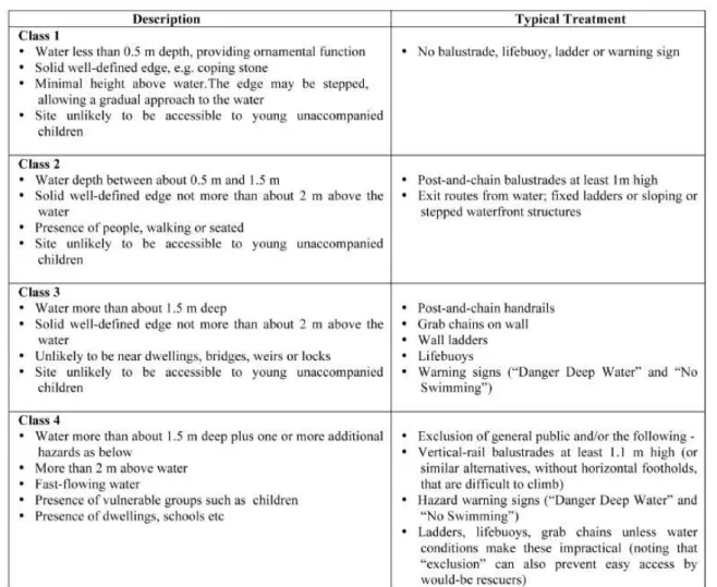
5 SAFETY
Safety has become another increasingly important aspect of design for locks. As well as highlighting many areas of design that can lead to increased safety (e.g. mooring, lighting, signs, channel design and gate protection), the report (PIANC, 2009) also provides a classification of different types of water edge structure and gives guidelines for suitable safety treatment for each type. This is shown in Table 1 below.
REFERENCES
PIANC, 1986, Final Report of the International Commission for the Study of Locks, PIANC, Brussels.
PIANC, 2009, Report No.106, Innovations in Navigation Lock Design, PIANC, Brussels.
Paper 4 - Seine Nord Europe canal – Hydraulic design of locks
B.Deleu
VNF, Béthune, France
J.N.Maillet
EDF,Grenoble, France
ABSTRACT: hydraulic operation of a lock with separate water-saving basins and introduction of water through the chamber bottom, adopted as the reference solution during the preliminary design studies of the Seine Nord Europe Canal, has been studied using numerical and physical models.
These studies were used to size the chamber water supply system and define the most suitable design for the gate chamber controlling flows between the water-saving basins and the lock chamber.
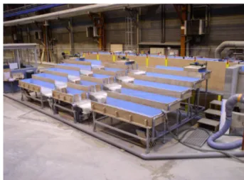
The 1:25 scale model built for the lock with the largest drop height (30m) enabled the numerical simulation results to be validated and fine-tuned, and certain operating parameters to be optimised.
.
1 INTRODUCTION
The Seine Nord Europe canal will operate by recycling lockage water. Recycling is planned for all locks, in other words the lock in the Oise valley, with a drop height of just 6.4 m, and the six locks with large drop heights (19.6 m, 15.5 m, 30 m, 22.5 m, 20 m and 25 m) between Noyon and the Dunkirk-Scheldt canal.
In order to limit discharges and thus the pumping costs at the locks, the locks with large drop heights are fitted with "water-saving basins". The advantage of these basins, situated on the sides of the lock chambers (integrated into the side walls or built as separate structures) is that they recover part of the lockage water for a descending boat (going from the upstream reach to the downstream reach) and restore it at the following lockage for an ascending boat (from the downstream reach to the upstream reach). 2 SCALE-MODEL STUDY
A 1:25 scale model was built in order to study the following aspects of operation of a lock, which has a drop height of 30 m:
- the total filling and emptying times
- the change in water level and longitudinal slope of the chamber water surface during filling and emptying
- water-saving basin filling and emptying procedures
- the lockage wave in the downstream reach - forces on boat moorings during filling and
emptying operations, for different boat types: boats 110 m long with a 3 m draught, 85 m long with a 2.5 m draught, and 10 m long (pleasure boats).
The model operates with Froude similitude conditions, with a time (λ=1/25) and velocity scale of λ0.5=1/5 and a flow rate scale of λ2.5=1/3125.
Figure 1. General view of the scale model.
Levels are measured continuously at a high frequency at 6 points in the lock chamber and upstream and downstream reaches, as well as in a
PIANC – Brussels Paper 4 - Page 2/3
water-saving basin. Forces are measured simultaneously on the two mooring lines of one of the boats.
2.1 Results obtained in normal operation
The filling time is of the order of 13 min to 13 min 30 sec and the emptying time is of the order of 13 min 15 s to 14 min.
The longitudinal slope in the lock chamber remains at 1‰ or less during filling and emptying. The slope over half of the chamber reaches values of the order of 0.8‰ during filling and 3‰ during emptying.
A wave with a maximum amplitude of 1.15 m is observed in the water-saving basins during filling. The wave is gradually damped in the basin. The period is of the order of 26 s.
In spite of the necessary streamlining of the angles of the stoplog wells, a short-duration eddy occasionally occurs at the end of emptying the water-saving basins (the existence of these stoplog wells in the basins, reserved for the stoplogs of the duct gates, and not represented during the initial tests, considerably reduced the initiation and development of this eddy phenomenon). There is a possibility that this eddy could entrain air into the distribution chamber in the case of the lowest basin.
The downstream lockage wave remains less than 0.27 m high (0.23 m on average).
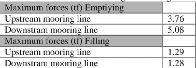
The mooring lines of the 105 m boat are mainly placed under strain during chamber/water-saving basin transfers, when the amplitude of slope variations on half of the chamber is greatest. The maximum forces measured during all the tests were 5.1 tf during chamber emptying. Chamber emptying puts more strain on mooring lines, in a more jerky manner, in the case of a loaded 105 m boat. The maximum forces reached on the mooring lines of the 85 m boat remain lower (< 3 tf). The maximum forces on the boat mooring lines, loaded to produce maximum squat, are shown in the table below for the case of the 110 m boat. No significant variation in mooring line forces was observed when two boats are in the lock chamber simultaneously, regardless of their size and position upstream or downstream.
Table 1. Maximum forces acting on mooring lines Maximum forces (tf) Emptiying
Upstream mooring line 3.76 Downstram mooring line 5.08 Maximum forces (tf) Filling
Upstream mooring line 1.29 Downstram mooring line 1.28
2.2 Results obtained in downgraded mode
Two downgraded modes were studied for the entire duration of chamber emptying of filling:
- failure of the lower water-saving basin to operate during chamber filling of emptying (shut-down for maintenance, failure of the gates to open, for example), thus doubling the load when emptying each water-saving basin and in the final stage of filling via the upstream headworks,
- only one of the two gates in the downstream headworks opens during chamber emptying. These downgraded operating modes do not produce any modification in the longitudinal slopes observed in comparison with normal operation.
When the lowest water-saving basin is not in service, the downstream lockage wave is 0.35 m high at the most (0.30 m on average). There is no aggravation of the lockage wave when only one downstream gates operates.
Maximum forces on the moorings are observed at the end of chamber emptying, owing to the greater disturbance (basin out of service or one downstream gate out of use) but the maximum normal operating values are rarely exceeded (a single maximum case of 6.4 tf observed with the 105 m boat).
The downgraded modes studied do not therefore aggravate conditions in the lock chamber. Only the chamber emptying wave in the event of a water-saving basin being out of service is increased owing to the fact that the peak flow rate is greater. This problem for navigation in the reach or for the safety of boats moored in the waiting area, can be solved by lengthening the end of emptying via the downstream gates.
3 OPTIMISATION OF THE HYDRAULIC SYSTEM
With the hydraulic concept studied here, there is potential for optimising the lockage durations.
For structures of identical height, a reduction in lockage duration would make it possible to improve the flow capacity of the traffic using the system, or for an identical traffic flow capacity, it would be possible to increase the maximum lift of the locks, thereby providing an opportunity to optimise the earthworks for the canal by raising the level of the watershed reach, hence reducing excess excavation.
There are two main possibilities for optimising the system:
- Optimising gate operation in the water-saving basins,
- Modifying the criterion of maximum discharge into or removal from the adjacent reaches.
The limitation on the rate at which water is discharged into or taken from the adjacent reaches is a very severe constraint on lockage time. For example, for a lock with a drop height of 30 m and 5 water-saving basins, this limitation currently means that about half the total lockage time is required to empty or fill the unsaved fraction, which represents only 2/7ths of the total volume. A more detailed study of the effects of the surge wave, its dissipation and the impact of currents on navigability may enable the intake or discharge rates authorised in the reaches to be increased and hence the lockage times to be reduced.
The exploratory calculations carried out show a potential gain by increasing the flow rate from 72 m3/s to 108 m3/s (maximum velocity in the running section of the reaches increasing from 0.35 m/s to 0.55 m/s). The time required for the last stage of emptying would thus drop from 370 s to 310 s. The maximum velocities in the water ducts would also drop from 4 m/s to 6 m/s, which remains low in comparison with the permissible velocities currently adopted in the USA and China, for example (10 m/s and over).
It may be possible to reduce even further or even remove the requirement concerning the flow rate for filling or emptying the first or last layer of water by creating additional basins that would temporarily store some or all of the quantities not saved at present (2/7ths of the chamber for a lock with a 30 m lift). The manner in which these communicate with the adjacent reaches would be designed in such a way as to stagger the flow taken from or discharged into the canal (by spreading and lowering the peak flow rate).
PIANC – Brussels Paper 5, part A - Page 1/4
Paper 5, part A - Innovations in Lock Filling and Emptying Systems
J. Webb
US Army Corps of Engineers (Washington D.C., USA)
ABSTRACT: Hydraulic systems for filling and emptying locks can be divided into two main types. One is the filling and emptying “through the heads”; and the other is the “through longitudinal culverts” system. Within these filling and emptying systems, the “In Chamber Longitudinal Culvert System” (ILCS) and “Pressure Chamber under the Floor System” are new types developed after 1986. In recent years some locks in Germany have been equipped with a filling system which uses a pressure chamber beneath the floor. This type of filling system has proven to be very efficient especially in combination with water saving basins. In general the ILCS system could be used for intermediate lift locks. Under specific conditions, such as in rock, a large saving in lock wall construction costs could be realized if the lock filling and emptying culverts were located inside the lock chamber rather than within the lock walls. This paper and the accompanying presentation review these systems, previous implementations, guidelines for the selection of a system, utilization in combination with other methods such as water saving basins, and optimization of the systems.
1 TYPES OF HYDRAULIC SYSTEMS
The hydraulic systems for filling and emptying locks can be divided into two main types. One is the filling and emptying “through the heads”; and the other is the “through longitudinal culverts” system.
1.1 Through the Heads Systems
The use of the “through the heads” systems may induce potentially dangerous currents and considerable waves in the lock during filling and emptying.
To avoid these problems, several measures are possible: the lock can be operated with a very slow valve schedule, the lock can be equipped with an energy dissipation system to reduce the current and waves, or the lock can be monitored continuously to avoid safety hazards, so that a lock keeper can bypass the automated filling/emptying mode under certain conditions.
1.2 Through Longitudinal Culverts Systems
“Through longitudinal culvert” systems are a
more sophisticated method of filling compared to the methods described above. The “longitudinal culvert” systems can be subdivided into two categories according to the way the water goes into the lock chamber.
Systems with asymmetric distribution of flow along the length of lock chamber include wall culvert side port systems, In Chamber Longitudinal Culvert Systems (ILCS), wall culvert bottom lateral systems, wall culvert bottom longitudinal systems, and longitudinal culverts under the lock floor.
Systems with symmetric distribution of flow along the length of lock chamber include dynamically balanced lock filling systems and pressure chamber systems.
2 NEW HYDRAULIC SYSTEM CONCEPTS Within the filling and emptying systems mentioned the “In Chamber Longitudinal Culvert System” and “Pressure Chamber under the Floor System” are new types developed after 1986. The PIANC, 2009 Report (PIANC, 2009) addresses these new concepts.
2.1 Pressure Chamber System
In recent years some locks in Germany have been equipped with a filling system which uses pressure chambers beneath the floors. This type of filling system has proven to be very efficient, especially in combination with water saving basins.
The pressure chamber is connected to the main chamber through arrays of nozzles. This type of filling system results in a very smooth filling of the
chamber even for high lifts, combined with a short filling time. Additionally water saving basins can easily be attached to the pressure chamber, so that a smooth operation is possible for filling and emptying through the culverts and the saving basins.
2.2 In-Chamber Longitudinal Culvert System
The design philosophy for the ILCS was to develop a system that performed almost as efficiently as the side-port filling and emptying system. In recent years the investigations of the ILCS were carried out in the United States (Hite J, 2003). In general the ILCS system could be used for intermediate lift locks, but it has been used in USA for low lift. With the ILCS the culverts are taken out of the wall and moved to the floor of the chamber, which allows for alternative lock wall construction such as RCC or in-the-wet construction.
Under specific conditions, such as in rock, a large saving in lock wall construction costs could be realized if the lock filling and emptying culverts were located inside the lock chamber rather than within the lock walls.
2.3 Guidelines for the Selection of the Hydraulic System and its Layout
In the selection of a filling and emptying system, the following factors should be taken into consideration: lift height, time for filling or emptying the lock, lock chamber sizes, permissible investments for the lock, and maximal forces on the vessel.
The following principles should be used in selecting a filling and emptying system: the filling time should be as short as possible (based on the specified capacity and construction costs), water movement and turbulence in the chamber must be limited, the forces on the vessels and thus in the hawsers must not exceed established criteria, entrapment of large air bubbles in the filling system must be avoided, cavitation should be avoided if economically possible or adequate protective measures must be taken, and currents in lock approaches should be reduced to a minimum so that there will be no adverse effect on vessels waiting to lock or maneuvering in the approaches.
There are several ways to select the hydraulic system. Generally, the admissible forces on the vessel and the filling time govern the choice of the system. As these parameters are difficult to assess during initial design phase, simple approaches are often used. Two will be discussed here.
As a general guideline, it is important to maintain the symmetry of the filling system with respect to the water surface if filling times are to be minimized without creating excessive ship forces.
The traditional way to achieve this is based on the lock lift height (H). As discussed in the PIANC’86 Report (PIANC, 1986), locks can be classified according to the lift height as follows: low lift height (H < 10m), intermediate lift (10m < H < 15m), and high lift height (H>15m). It must be pointed out that this classification was derived for inland waterway navigation and is not valid for seagoing vessels and sea locks.
For “low lift locks” a through the heads system or simple longitudinal culvert system can be used. Note that a short culvert system may require advanced energy dissipation chamber if a short filling time is a requirement. In any case, the filling process is not balanced along the chamber length.
For “intermediate lift locks” wall culvert side port systems and simple longitudinal culvert systems may be suitable. Here, the filling process is a better balanced along the chamber length. We can mention in this category: wall culvert side port systems, and longitudinal culverts under the floor with side or top outlets.
“High lift locks” require a more complex culvert system. It is necessary that the filling process is as symmetric in relation to the chamber as possible.
A second selection approach is based on the M coefficient (Eq. 1), as proposed by the (Chinese Code, 2002) for filling and emptying system of ship locks.
M=T/H 1/2 (Eq. 1) Where, H(m) is the lift height of lock and T(min) the time to fill the chamber. The value of M could be used to choose the relevant types of the hydraulic system. These values have to be based on reference values based on allowable ship forces during the locking process.
In the first approach, the lock lift height (H) is the only factor involved in the selection of the filling and emptying system. In the second approach, the use of the M coefficient allows considering both the
lift height (H) and the locking time (T)
simultaneously. The admissible ship forces must be regarded separately and will influence the decision process. Therefore, for seagoing vessels, the coefficient M must be considered differently.
Finally it should be noted that these approaches can be a helpful estimate if enough experience is available. Theses guidelines are not one-size-fits-all
PIANC – Brussels Paper 5, part A - Page 3/4
approaches, as neither the admissible ship forces nor the chamber dimensions are regarded directly. Another key parameter for the selection of the relevant hydraulic system is the flow variation (“how fast is the flow velocity changing during the locking”). Such variations tend to lead to waves in the chamber. Obviously a slow variation is better, as a faster variation requires a more complex and expensive hydraulic system or the locking times have to be increased.
If water enters only through the lock heads (short culverts or through the gates), translation waves occur in the longitudinal direction of the lock chamber and will be reflected against the ships and the opposite lock gate head.
If water-jets coming out of the lock chamber inlets act directly on the ship hull, the momentum of these jets directly produces forces on the hull, and in addition the water level in the chamber will be locally affected. This phenomenon induces unsteady longitudinal loads to the moored ships and even some transversal forces. This can be avoided if the lock chamber is deep enough and if the flow is passing below the ship hull (Fig. 1).
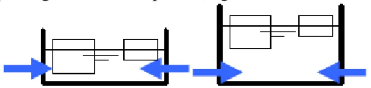
Fig. 1: Impact of the Culvert Side Port System
From the users’ point of view transverse forces can be a major problem. The main reasons for transverse forces are: asymmetric filling system / operation, asymmetric position of the vessel, and jets which directly touch the hull.
With a wall culvert side port system direct flow acting on the ship side (if the outlet ports are not deep enough beneath the vessel) can induce significant transverse forces (Fig. 1). In addition, if the culverts are not fed perfectly symmetrically to the centre of the lock (along the length of the lock), additional forces occur.
There are different practices concerning the positions of the outlet ports in the lock chamber. Practice in USA and China is to stagger the positions of the outlet ports so that the jets from one side of the lock do not directly collide with the jets from the other side. In some European countries, such as Belgium, it is usual to arrange the ports face-to-face to force the energy dissipation to occur at localised points.
If leveling is not carried out uniformly over the entire length of the lock chamber, longitudinal loads will also act on the ships. With wall culverts and even with longitudinal culverts, the discharge is not uniformly distributed along the lock length. Uniform distribution can be enhanced by using bigger culverts and even more by using symmetric systems like the dynamically balanced lock filling systems or a pressure chamber system. The dimensioning of the culverts is additionally influenced by the need to limit cavitation and wear in the culverts. In many countries, limitations on the average flow speed in the culverts are used for this purpose (12m/s in China and 6-10m/s in Europe). It should be pointed out, that the flow speed is not a sufficient criterion, as cavitation is largely influence by the pressure field and the shape of the hydraulic system.
For locks with a deep and perforated bottom, flow enters in the chamber vertically by small holes in the floor. If there is a great volume of water under the perforated floor and a great number of holes distributed regularly in the surface of the floor, water is transferred uniformly by the bottom of the lock chamber into or out of the lock chamber. With this kind of system, only very small waves are generated even if the rate of flow strongly varies during the locking. Then, the moored ships are not heavily loaded in the longitudinal and transverse directions.
Thus, the choice of the lock hydraulic system depends not only on the lift height (H), the time of locking, the presence of WSBs, the lock dimensions and the available budget, but also on the variation of the discharge (translation waves in the lock chamber and in the adjacent reaches) and the allowable forces on the mooring cables of vessels.
3 WATER SAVNG CONCEPTS
3.1 Determination of Saving Needs and Selection of the Water Saving System
The water saving needs are defined during the studies of water resources management, taking into account the assumed traffic, evaporation, infiltration, canal water tightness and climate changes. From these studies the expected water consumption of the lock itself is assessed.
The global water saving system of the lock is a combination or choice of different systems: pumping, WSBs, intermediate gate inside the chamber, twin synchronized locks, and lock ladders.
In order to select the best option, these various systems/devices have to be designed and optimized
simultaneously by a technical and economic assessment in relation to the existing lift height and the energy cost. The main choice criteria are: construction cost, operating cost, energy saving and environmental cost, filling time and traffic, available space, and the influence on water level in the upper and lower reaches.
The intermediate gate, twin lock or lock ladder can lead to considerable water saving. Nevertheless they can be very expensive and are the best solutions only in specific cases. Twin synchronized locks can be accepted only if they are economically justified by the traffic, and an intermediate gate may be a good solution if a significant number of lockages are to be made with small boats. The shortcoming of a lock ladder instead of a single lock is to increase the number of gates and ship operations (mooring, etc.), therefore the traffic capacity is lower.
The water saving basin solution has some shortcomings too: high initial investment (compared to pumping station), more complex structure, numerous gates and a slightly longer filling /emptying time.
Nevertheless, because of reasons of life cycle cost, energy saving and environmental cost, this solution will be probably the best one where the need for water saving is permanent and larger than a minimum value (specific to each case).
Due to the uncertainties linked to traffic evolution and energy cost a possibility is to build the lock first without WSB but with pre-connection for future WSBs to be eventually built in the future.
3.2 Water Saving Basins (WSBs)
Recent examples of locks with saving basins are described in project reviews.
In the Panama 3rd lane project, a triple lift lock has been designed combined with 9 saving basins (3 basins for each lock chamber) allowing a very high saving rate (87%) when compared to a single lift lock without WSBs .
A lock with WSBs better fits to a filling/emptying system with longitudinal culverts and inlets on the sidewalls or even distributed through the floor because the successive openings/closures of valves induce significant discharge and therefore higher risk of disturbance of the water level on the lock chamber (balancing waves along the lock chamber).
Division into symmetrical half saving-basins to facilitate the maintenance and reduce the impact in case of problem (closure of ½ basin versus 1 basin). That may be a useful solution if a short filling time
is required. In this case, half basins can be placed symmetrically on both sides of the lock.
It is better to have multiple culverts between a basin and the chamber for reliability reasons and to avoid a high degradation of performance during the maintenance of a valve or a culvert. With multiple culverts per basin the water distribution along the axis can be enhanced and thus faster filling can be achieved (for a higher building cost).
The choice of the hydraulic filling system must be done considering the real water lift height between 2 basins. However, when the use of WSBs is economically relevant, that also means that the lock lift height is rather important and that a reduced filling time is expected. This is why an advanced and performing hydraulic system (longitudinal culverts) is generally needed (no matter what the value of the M coefficient).
The M equation (1) must be evaluated differently for locks with WSBs, because the hydraulic situation is not exactly the same than without WSB. It is necessary to consider the lift height and the filling time of each single WSB (and the residual filling) separately to achieve a multitude of M values. Then, the smallest M value governs the choice of the hydraulic system.
3.3 High Rise Navigation Lock Using WSBs
Traditionally the maximum lift height of a lock is considered as being limited at 25, 30 or 40 m due to hydraulic aspects, mainly cavitation. If WSBs are used there is no limit for the lock height. Locks of 100 or 150 m height can be considered if the filling and emptying of each WSB is studied to avoid cavitation. This means that cavitation limits the height of the saving basins but not their number and therefore the total lift height of a lock (Dehousse 1985, Dehousse et al., 1989 and 1993). For instance a lock of 100m lift height with 6 water saving basins is similar for cavitation and hydraulic aspects to a series of four locks of 25m lift height.
REFERENCES
PIANC, 1986: “Locks”, Final Report of the International
Commission for the Study of Locks, PIANC, Brussels
PIANC, 2009: “Innovations in Navigation Lock Design”, Final Version 20b, PIANC-InCom-WG 29
Hite, J., 2003: “In-chamber Longitudinal Culvert Design for
Lock Filling and Emptying,” Technical Report HL-94-6,
U.S. Army Engineer Research and Development Center, Vicksburg, MS.
Chinese Code, 2002: “Design Code for Filling and Emptying
PIANC – Brussels Paper 5, part B - Page 1/2
Paper 5, part B - Innovations in Traditional Filling and Emptying
Systems
Wu Peng
Planning and Design Institute for Water Transportation, Beijing, P.R. China
ABSTRACT: Energy dissipation is a major problem in filling and emptying systems. For a specific filling and emptying system, you can raise the hydraulic efficiency of the system (or shorten the filling time) by optimizing the energy dissipation measures. Some examples are introduced here.
1 INTRODUCTION
The objectives to choose a proper filling and emptying system are to get a proper filling/emptying time (not as short as possible) and to get a lower cost with the proper filling time.
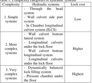
In general the simpler the filling and emptying system is, the lower the lock cost as shown in table 1.
Table 1: Complexity categories of hydraulic systems Complexity Hydraulic systems Lock cost
1. Simple systems
- Through the head system
- Wall culvert side port system
- In Chamber longitudinal culvert system (ILCS)
Low
2. More complex systems
- Wall culvert bottom lateral system
- Longitudinal culverts under the lock floor - Wall culvert bottom longitudinal system - Longitudinal culverts under the lock floor
Higher
3. Very complex
systems
- Dynamically balanced lock filling system - Pressure chamber under the floor
Highest
For a specific filling and emptying system, if you can raise the efficiency of the system (or shorten the filling time) you can make the lock cost lower (or save monney).
Following are some examples to improve the effciency of filling and emptying systems.
2 PARTIAL DISTRIBUTED SYSTEM
Through the head system is a very simple and low cost system. But it can be only used for locks with very low lift height.
Based on the principle that distributed (longitudinal culvert) filling and emptying system could improve the operation efficiency of locks, a partial distributed system could be used to raise the efficiency and reduce the cost. The short culverts of the system were extended into chamber walls with bottom lateral branch culverts (Fig.1).
Figure 1 Partial distributed filling system
3 DOUBLE DITCHES ENERGY DISSIPATION SYSTEM
To avoid dangerous currents at the outlets of filling and emptying system, measures should be taken for energy dissipation. Double ditches are effective system for energy dissipation. Figure 2 shows the double ditches used in bottom lateral system and Figure 3 used in In-chamber Longitudinal Culvert System (ILCS). Compared with one ditch system the filling time was shortened.
Figure 2 Double ditches used in bottom lateral system
Figure 3 Double ditches used in ILCS system
4 ENERGY DISSIPATION FOR SIDE PORT SYSTEM
For side port system enough submergence is required to prevent direct action of the port jets against the bottom of the vessel. But in many cases a little more submergence will lead to much cost.
Tests have shown that if port deflectors was arranged in chamber (Figure 4) the jet into the chamber was spread by the deflectors evenly and the hydraulic condition was improved. So the minimum submergence could be reduced.
Figure 4 Side Port System with Port Deflectors
Figure 5 and figure 6 are results of numerical tests of port jet without and with deflectors.
Figure 5 Flow Distribution without Deflectors
Figure 6 Flow Distribution with Deflectors
The height of the deflectors and the distance between the deflectors and the port should be decided carefully.
PIANC – Brussels Paper 6 - Page 1/1
Paper 6 - The Panama Canal’s Third Set of Locks Project
Juan Wong H.
Panama Canal Authority, Panama, Republic of Panama
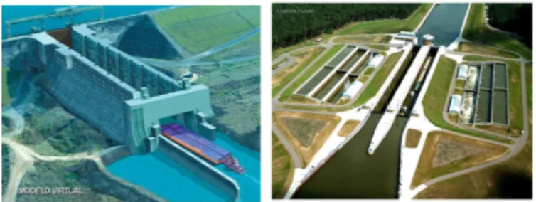
ABSTRACT: One of the world’s greatest engineering achievements, the Panama Canal plays a vital role in world shipping. But even though at the time of their construction the dimensions of the existing locks set the standard that defined the ‘Panamax’ size container ships and bulk carriers, today’s locks are nearing their maximum throughput capacity in spite of all the infrastructure improvements of past decades. To accommodate growing traffic demand, particularly by containerships in the route between Northeast Asia and ports on the US East Coast, and also to accommodate post-Panamax ships, the Panama Canal has started executing its ambitious expansion plan, which is scheduled for completion by 2014.
The Panama Canal conducted more than 120 studies that were analyzed and integrated into the decision making process to select the most suitable, efficient, effective alternatives that would enable the optimization of the Third Set of Locks Project. The studies for the Panama Canal Capacity Expansion Program are described in full in the Panama Canal Master Plan 2005-2025 and in the Proposal for the Canal Expansion approved on October 22, 2006 through national referendum. The Master Plan and summaries of many of the relevant studies can be found at http://www.pancanal.com/eng/plan/index.html.
The Panama Canal Expansion Program involves six main projects, mainly: 1) the construction of two set of locks at the Atlantic and Pacific ends of the Canal; 2) the dry excavation of an access channel connecting the Gaillard (Culebra) Cut to the new Pacific locks; 3) dredging of the existing navigational channels of the Atlantic Ocean entrance; 4) dredging of the existing navigational channels Pacific Ocean entrance, 5) dredging the Gatun Lake and Gaillard Cut fresh water navigational channels; and 6) raising the level of Gatun lake by 45 cm through modifications to existing land based infrastructure. Overall the activities of the Expansion Program will span over the 80 kilometers of the Panama Canal.
One set of locks will raise/lower vessels on the Atlantic end of the Canal, east of the existing Gatun Locks, and the other set of locks will raise/lower vessels on the Pacific end, southwest of the existing Miraflores Locks. Each facility will be comprised of three consecutive lock chambers, which will use gravity to lift the vessels from one ocean to an average height of 26 meters at lake level and lower them back to ocean level on the opposite end. Each chamber will be accompanied by three lateral water-saving basins for a total of nine water-saving basins per lock. Each lock chamber will be 427 m to 458 m long, 55 m wide and 18.3 m deep as a minimum, to allow the transit of vessels up to 49 meters in beam, and overall length of up to 366 meters and a draft up to 15.2 meters in tropical fresh water, which corresponds to a 12,000 TEU nominal capacity containership loaded with 19 container rows across deck.
GUPC Locks Design
Pacific Locks
GUPC Locks Design Pacific Locks
Paper 7 - Mooring forces and ship behaviour in navigation locks
T. De Mulder
Flemish Authorities - Mobility and Public Works Department Flanders Hydraulics Research - Waterbouwkundig Laboratorium
Berchemlei 115, B-2140 Antwerp, Belgium [email protected]
ABSTRACT: This contribution reflects upon the issue of mooring line forces and ship behaviour during filling/emptying of inland and maritime navigation locks. The philosophy behind the so-called hawser force criterion and the classical approach to deal with it in design studies, is described first. Secondly, some innovations in the definition, verification and validation of the design criteria are highlighted.
1 INTRODUCTION
The hydraulic design of a lock filling/emptying system aims at (among other issues) minimization of the filling/emptying time, constrained by the so-called hawser force criterion. The latter criterion is meant to guarantee a certain degree of safety and comfort to a moored vessel during lockage.
2 HAWSER FORCE CRITERION
2.1 Philosophy
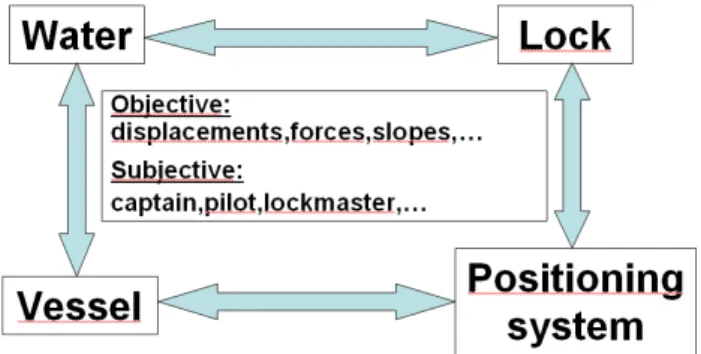
The hawser force criterion attempts to quantify the necessary limitation of ‘turbulence’ (in the wide sense) generated by the lock filling/emptying, in order to limit the displacement of the vessel and the associated forces in the vessel-positioning system (e.g. mooring lines). Notice that the water flow, the lock (chamber and filling/emptying system), the vessel and its positioning system mutually interact, see Figure 1.
Figure 1. Constituting elements of a hawser force criterion
2.2Criterion
The appreciation of safety and comfort during a lockage contains both objective (e.g. forces on the vessel, forces in the mooring lines, slope of the water surface, slope of the vessel, displacement of the vessel) and subjective elements (e.g. feeling of the captain, pilot, lockmaster).
The hawser force criterion sets an upper bound (i.e. a threshold) to an objective element (i.e. definition of the criterion). To assess whether a given filling/emptying system meets the defined criterion, a verification tool should be available. In order to assess that the adopted definition and its associated verification tool lead to both safe and comfortable as well as economic lockages, validation efforts should be carried out.
2.3 Classical approach
The ‘classical’ approach consists of a hawser force criterion being defined in terms of the hydrodynamic force on the vessel. This force should not exceed a given threshold value, expressed in absolute terms or in relative terms (as a fraction of the vessel’s displacement weight).
A scale model is used as a verification tool. To avoid a complicated measurement set-up, no attempt is (usually) made to represent the real vessel-positioning system (consisting of e.g. mooring lines, winches, bollards) in the scale model.