HAL Id: hal-01193178
https://hal.inria.fr/hal-01193178
Submitted on 13 Oct 2015
HAL is a multi-disciplinary open access
archive for the deposit and dissemination of
sci-entific research documents, whether they are
pub-lished or not. The documents may come from
teaching and research institutions in France or
abroad, or from public or private research centers.
L’archive ouverte pluridisciplinaire HAL, est
destinée au dépôt et à la diffusion de documents
scientifiques de niveau recherche, publiés ou non,
émanant des établissements d’enseignement et de
recherche français ou étrangers, des laboratoires
publics ou privés.
Revisiting Clustered Microarchitecture for Future
Superscalar Cores: A Case for Wide Issue Clusters
Pierre Michaud, Andrea Mondelli, André Seznec
To cite this version:
Pierre Michaud, Andrea Mondelli, André Seznec. Revisiting Clustered Microarchitecture for Future
Superscalar Cores: A Case for Wide Issue Clusters. ACM Transactions on Architecture and Code
Optimization, Association for Computing Machinery, 2015, 13 (3), pp.22. �10.1145/2800787�.
�hal-01193178�
case for wide-issue clusters
PIERRE MICHAUD, IRISA/Inria ANDREA MONDELLI, IRISA/Inria ANDR ´E SEZNEC, IRISA/InriaDuring the last 10 years, the clock frequency of high-end superscalar processors did not increase. Perfor-mance keeps growing mainly by integrating more cores on the same chip and by introducing new instruc-tion set extensions. However, this benefits only some applicainstruc-tions and requires rewriting and/or recompiling these applications. A more general way to accelerate applications is to increase the IPC, the number of in-structions executed per cycle. Though the focus of academic microarchitecture research moved away from IPC techniques, the IPC of commercial processors was continuously improved during these years.
We argue that some of the benefits of technology scaling should be used to raise the IPC of future su-perscalar cores further. Starting from microarchitecture parameters similar to recent commercial high-end cores, we show that an effective way to increase the IPC is to allow the out-of-order engine to issue more micro-ops per cycle. But this must be done without impacting the clock cycle. We propose to combine two techniques: clustering and register write specialization. Past research on clustered microarchitectures fo-cused on narrow issue clusters, as the emphasis at that time was on allowing high clock frequencies.
Instead, in this study, we consider wide issue clusters, with the goal of increasing the IPC under a constant clock frequency. We show that, on a wide-issue dual cluster, a very simple steering policy that sends 64 consecutive instructions to the same cluster, the next 64 instructions to the other cluster, and so forth, permits tolerating an inter-cluster delay of 3 cycles. We also propose a method for decreasing the energy cost of sending results from one cluster to the other cluster.
1. INTRODUCTION
For several decades, the clock frequency of general purpose processors was growing thanks to faster transistors and microarchitectures with deeper pipelines. However, about 10 years ago, technology hit leakage power and temperature walls. Since then, the clock frequency of high-end processors did not increase. Instead of increasing the clock frequency, processor makers integrated more cores on a single chip, enlarged the cache hierarchy and improved energy efficiency.
Putting more cores on a single chip has increased the total chip throughput and ben-efits some applications with thread-level parallelism. However, most applications have low thread-level parallelism [Blake et al. 2010]. So having more cores is not sufficient. It is important also to accelerate individual threads.
If the clock frequency remains constant, the only possibility left for higher single-thread performance in future processors is to exploit more instruction-level parallelism (ILP). Certain microarchitecture improvements (e.g., better branch predictor) simulta-neously improve performance and energy efficiency. However, in general, exploiting more ILP has a cost in silicon area, energy consumption, design effort, etc. Therefore, the microarchitecture is modified slowly, incrementally, taking advantage of technol-ogy scaling. And indeed, processor makers have made continuous efforts to exploit more ILP, with better branch predictors, better data prefetchers, larger instruction windows, more physical registers, and so forth. For example, the Intel Nehalem mi-croarchitecture can issue 6 micro-ops per cycle from a 36-entry issue buffer, while the more recent Intel Haswell microarchitecture can issue 8 micro-ops per cycle from a 60-entry issue buffer [Intel 2014].
This work is partially supported by the European Research Council Advanced Grant DAL No 267175. Author’s address: P. Michaud, A. Mondelli, A. Seznec, IRISA/Inria, Campus de Beaulieu, 263 Avenue du G´en´eral Leclerc, 35042 Rennes Cedex, France.
In this paper, we try to depict what future superscalar cores may look like in 10 years. We argue that the instruction window and the issue width can be augmented by combining clustering [Lowney et al. 1993; Kessler 1999; Palacharla et al. 1997] and register write specialization [Canal et al. 2000; Zyuban and Kogge 2001; Seznec et al. 2002b].
A major difference with past research on clustered microarchitecture is that we as-sume wide issue clusters (≥ 8-issue), whereas past research mostly focused on narrow issue clusters (≤ 4-issue). Going from narrow issue to wide issue clusters is not just a quantitative change, it has a qualitative impact on the clustering problem, in partic-ular on the steering policy. Past research on steering policies showed that minimizing inter-cluster communications while achieving good cluster load balancing is a diffi-cult problem. One of the conclusions of a decade of research on steering policies was that simple steering policies such as Mod-3 [Baniasadi and Moshovos 2000] generate significant IPC loss, while steering policies minimizing IPC loss are too complex for hardware-only implementations [Salverda and Zilles 2005; Cai et al. 2008].
Our study shows that considering wide issue instead of narrow issue clusters has a dramatic impact on the performance of Mod-N, one of the simplest steering policy. Mod-N sends N consecutive instructions to a cluster, the next N instructions to another cluster, and so forth in round-robin fashion [Baniasadi and Moshovos 2000]. Baniasadi and Moshovos found that, on narrow issue clusters, the optimal value of N is generally very small, advocating a Mod-3 policy. To the best of our knowledge, after Baniasadi and Moshovos’s paper, nobody has considered Mod-N policies other than Mod-3 .
We find that, with wide issue clusters, if the instruction window is large enough and considering a realistic inter-cluster delay, the optimal value of N is much larger than three, typically several tens. Owing to data-dependence locality, a Mod-64 policy leads to much fewer inter-cluster communications than a Mod-3 policy. As a result, Mod-64 tolerates greater inter-cluster delays than Mod-3. Moreover, about 40% of the values produced by a cluster do not need to be forwarded to the other cluster, which permits reducing the energy spent in inter-cluster communications.
This paper is organized as follows. Section 2 argues for using some of the benefit of technology scaling for increasing single-thread IPC. Section 3 discusses some known solutions for enlarging the issue width and the instruction window. We describe our simulation set-up in Section 4. In Section 5, we explore the impact on IPC of various microarchitecture parameters, and we show that, by doubling simultaneously all the parameters of a modern high-end core, the IPC of SPEC INT benchmarks could be in-creased by 25% on average, that of SPEC FP by 40%. Section 6 studies the impact on IPC of clustering the out-of-order engine. We find that significant IPC gains are still possible, despite the inter-cluster delay, provided the instruction window parameters are doubled. We show that a Mod-64 steering policy tolerates inter-cluster delays of a few cycles. Section 7 explains how the energy consumption of inter-cluster communica-tions can be reduced by detecting micro-ops whose results are not needed by the other cluster. We discuss related work in Section 8, and conclude this study in Section 9. 2. A CASE FOR INCREASING SINGLE-THREAD IPC
If the clock frequency remains constant, the only possibility left for increasing the single-thread performance of future processors is to exploit more ILP.
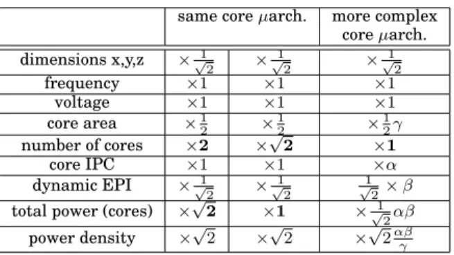
Table I shows three possible scenarios for exploiting one step of technology scaling under constant clock frequency and constant voltage1, assuming identical cores. The
1High leakage currents make difficult to scale down the voltage without severely hurting transistor speed.
This is one of the reasons for voltage scaling down only very slowly [ITRS 2013]. We conservatively assume a constant voltage.
Table I. Three possible scenarios for exploiting one step of tech-nology scaling, assuming constant frequency, constant voltage and homogeneous cores
same core µarch. more complex
core µarch. dimensions x,y,z ×√1 2 × 1 √ 2 × 1 √ 2 frequency ×1 ×1 ×1 voltage ×1 ×1 ×1 core area ×1 2 × 1 2 × 1 2γ number of cores ×2 ×√2 ×1 core IPC ×1 ×1 ×α dynamic EPI ×√1 2 × 1 √ 2 1 √ 2× β
total power (cores) ×√2 ×1 ×√1
2αβ
power density ×√2 ×√2 ×√2αβγ
core power, core IPC, EPI (energy per instruction) and clock frequency are related as follows:
core power = EPI × IPC × frequency
If voltage remains constant, technology scaling decreases the switching energy 1 2CV
2
only by reducing capacitances C, i.e., roughly as √1
2[Dennard et al. 1974]. Hence if we
consider a fixed core microarchitecture, the silicon footprint reduction from technology scaling means roughly a √1
2 reduction of the dynamic EPI.
The second and third column in Table I assume a fixed core microarchitecture. The first scenario (second column) corresponds to doubling the number of cores on each new technology generation, which technology scaling makes possible in a constant silicon area. However, this scenario leads to an increase of the total power (this is the dark silicon problem [Esmaeilzadeh et al. 2011]).
The second scenario (third column) corresponds to increasing the number of cores but more slowly than what technology scaling permits, so as to keep the total power constant. Power density increases but remains inversely proportional to the circuit di-mensions, hence hot spots temperature remains constant (see formula (1) in appendix). The third scenario (fourth column of Table I) shows a situation where the number of cores is kept constant, but single-thread performance is increased with a more complex core microarchitecture2. For example, a 10% increase of core IPC (α = 1.10) which is obtained at the cost of 28% more EPI (β = 1.28)3results in a constant total power and
10% overall EPI reduction after scaling down the feature size.
The main point is that the core microarchitecture complexity can be increased progressively, over several technology generations, with the EPI globally decreasing thanks to technology scaling.
3. SOLUTIONS FOR WIDE-ISSUE CORES
We show in Section 5 that significant IPC gains can be obtained by increasing the issue width, the front-end width and the instruction window size. We describe in this
2The second and third scenario of Table I do not exclude each other. They can be used at different
tech-nology generations. Moreover, keeping the number of cores constant does not preclude introducing more simultaneous multithreading (SMT) contexts.
3Making the core more complex does not necessarily increase the EPI (factor β). A large fraction of the total
CPU power is static power from leakage currents. And a large fraction of this static power is gateable on modern processors, i.e., can be turned off once a task is finished. Increasing the IPC makes the execution time shorter, and may reduce static energy consumption [Czechowski et al. 2014].
section some solutions that are already known and that we believe are realistic, with an emphasis on clustering.
3.1. Clustering
Clustering was proposed in the 1990’s as a solution for reducing the clock cycle of superscalar processors [Palacharla et al. 1997; Farkas et al. 1997]. The basic idea is to partition the execution units (EU) into clusters, such that the output of one EU can be used as input by any other EU in the cluster in the next clock cycle through a local bypass network [Gonz ´alez et al. 2011]. Clustering can also be applied to the issue buffer (one issue buffer partition per cluster). Hence clustering is a solution to two of the most important frequency bottlenecks in the out-of-order engine: the bypass network and the issue buffer. The price to pay is that communications between clusters require an extra delay, which may impact the IPC.
A natural form of clustering, which has been used in several superscalar processors, is to have an integer cluster and a floating-point cluster. This form of clustering does not generate intercluster communications, and the term “clustered microarchitecture” is mostly applied to cases where intercluster communications are frequent.
Clustering introduces a degree of freedom for instructions that can execute on sev-eral clusters. Choosing on which cluster to execute an instruction is called steering. Microarchitectures such as the DEC Alpha 21264 [Farrell and Fischer 1998; Kessler 1999] that cluster the EUs but not the scheduler do the steering at instruction is-sue (execution-driven steering [Palacharla et al. 1997]). Microarchitectures such as the IBM POWER7 [Sinharoy et al. 2011] that cluster both the EUs and the scheduler do the steering before inserting the instruction into the issue buffer (dispatch-driven steering [Palacharla et al. 1997]).
Execution-driven steering does a good job at mitigating the impact of the inter-cluster delay, as the scheduler can send an instruction to the inter-cluster where it can execute sooner [Palacharla et al. 1997]. However, execution-driven steering limits the size of the issue buffer, not only because the issue buffer does not benefit from cluster-ing (unlike the bypass network), but also because postponcluster-ing the steercluster-ing until issue makes it part of the scheduling loop, which impacts the clock frequency.
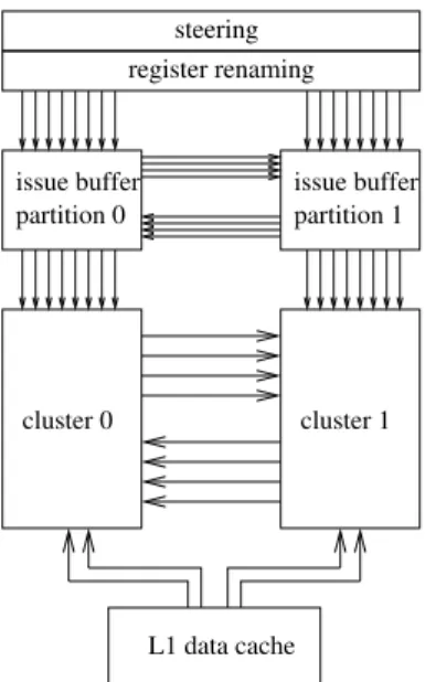
In this study, we consider only dispatch-driven steering, i.e., the issue buffer is clustered just like the EUs and the bypass network, and the steering is done before the instruction enters the issue buffer. An example of dispatch-driven clustered scheme is shown in Figure 1.
We assume symmetric clusters, i.e., the two clusters are identical and can execute all micro-ops. An advantage of symmetric clustering is that in simultaneous multithread-ing (SMT) mode, the clusters can execute distinct threads and the inter-cluster bypass network can be clock-gated.
3.2. Issue buffer
Clustering the issue buffer like the EUs (as in the IBM POWER7) permits increasing the total issue buffer capacity without impacting the clock cycle: the select operation is done independently on each issue buffer partition, and the wake-up operation is pipelined between the partitions, taking advantage of the inter-cluster delay [Goshima et al. 2001].
3.3. Steering
Ideally, one wants both a good cluster load balancing and limited inter-cluster commu-nications. However, these two goals generally contradict each other. The main problem is to achieve a good trade-off between load balancing and inter-cluster communications while still being able to steer several instructions simultaneously.
L1 data cache cluster 0 cluster 1 issue buffer partition 1 register renaming steering issue buffer partition 0
Fig. 1. Example of 2-cluster OoO engine, assuming dispatch-driven steering and register write specializa-tion.
Some authors proposed steering policies taking into account register dependencies [Palacharla et al. 1997; Canal et al. 1999; Canal et al. 2000; Baniasadi and Moshovos 2000; Gonz ´alez et al. 2004]. However, these dependency-based steering policies are complex and make steering a clock frequency bottleneck, as the steering bandwidth must match the register renaming bandwidth.
Therefore we consider a very simple steering policy: Mod-N. Mod-N steers N instruc-tions to a cluster, the next N instrucinstruc-tions to the next cluster, and so on in round robin fashion [Baniasadi and Moshovos 2000]. Mod-N is simple enough to be implemented in hardware.
3.4. Write specialization
Executing more instructions per cycle requires to increase the number of read and write ports on the register file. However, the area and access energy of an SRAM array increases quickly with the number of ports, especially with write ports [Seznec et al. 2002b].
A simple solution to increase the number of read ports is to duplicate the physi-cal register file, as in the Alpha 21264 [Kessler 1999]. However this does not solve the problem for write ports. Register Write Specialization has been proposed to solve this problem [Seznec et al. 2002b]. For a clustered superscalar OoO engine, register write specialization means that each cluster writes in a subset of the physical regis-ters [Canal et al. 2000; Zyuban and Kogge 2001; Seznec et al. 2002b].
As an example, let us consider a single-cluster OoO engine using 128 physical regis-ters with 4 write ports and 8 read ports. A dual-cluster OoO engine has the double total issue width. We apply register write specialization, keeping the same total number of physical registers: partition 0 contains physical registers 0 to 63 and can be written only by cluster 0, partition 1 contains physical registers 64 to 127 and can be written only by cluster 1. To allow reading any register on both clusters, each cluster has a mir-ror copy of the register partition of the other cluster. That is, each cluster has 2 banks, each bank holding half of the registers and having 4 write ports and 8 read ports. If we keep the total number of physical registers constant, the area of the per-cluster
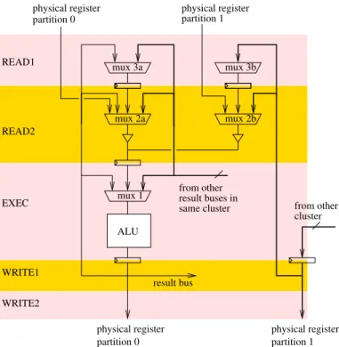
regis-mux 1 ALU mux 3a EXEC from other from other cluster result bus result buses in same cluster mux 3b mux 2a mux 2b partition 0 partition 1
physical register physical register
physical register partition 0 physical register partition 1 READ1 READ2 WRITE1 WRITE2
Fig. 2. Example of bypass network implementation for a dual-cluster OoO engine, assuming 2 register read/write cycles and register write specialization (a single execution port and single source operand are shown, comparators are not shown). The first bypass level (MUX 1) is not impacted by clustering, but this costs an extra cycle of inter-cluster delay.
ter file is roughly the same in the single-cluster and dual-cluster configurations. See Seznec et al. for more details [Seznec et al. 2002b].
Write specialization implies that steering should be finished before register renam-ing. This means that a complex steering policy cannot be completely overlapped with register renaming and would probably require extra pipeline stages for steering. How-ever, Mod-N steering is very simple and can be done while the rename table is being read.
3.5. Bypass network and inter-cluster delay
Increasing the issue width increases the bypass network complexity, which may im-pact the clock cycle. Clustering solves this problem by making the bypass network hierarchical. This is illustrated in Figure 2 on an example of bypass network imple-mentation for a dual-cluster OoO engine, assuming register write specialization. In this example, the first (i.e., most critical) bypass level (mux 1) is not impacted by clus-tering. However this costs an extra cycle of inter-cluster delay. Moreover, the physical distance between clusters requires pipelining the result buses to decrease RC delays. Hence a bypass network such as the one depicted in Figure 2 entails at least 2 cycles of inter-cluster delay, one (or more) from pipelining the result buses and one from iso-lating the first bypass level. Note that there are several possible implementations for a bypass network4. In our simulations, we consider inter-cluster delays of up to 3 cycles.
4Data movements in a pipelined bypass network consume a lot of power. This can be avoided with a
3.6. Level-one data cache
Increasing the issue width also means increasing the L1 data cache load/store band-width. Several solutions are possible for increasing the load/store bandband-width. Recent high-end processors use banking to provide the adequate bandwidth. Banking leads to the possibility of conflicts when several loads/stores issued simultaneously access the same bank. Several banking schemes are possible. In this study we assume that the 8 words in a 64-byte cache line are stored separately in 8 data-array banks, like in the Intel Sandy Bridge [Intel 2014].
3.7. Front-end bandwidth
Executing more instructions per cycle requires fetching more instructions per cycle. A possible way to increase the front-end bandwidth is to predict and fetch two basic block per cycles instead of one, as in the Alpha EV8 [Seznec et al. 2002a], and scale instruc-tion decode accordingly. However, decode itself may be a microarchitecture bottleneck for CISC instructions sets such as Intel x86. A trace cache (aka decoded I-cache or micro-op cache in the Intel Sandy Bridge and Haswell microarchitectures [Intel 2014]) addresses this issue. A trace cache stores in traces micro-ops that are likely to be exe-cuted consecutively in sequential order [Rotenberg et al. 1996].
A trace cache is also a solution to the register renaming bandwidth problem. When creating a trace, intra-trace dependencies can be determined and this information can be stored along with the trace. The number of read and write ports of the rename table can be reduced: each read-after-write or read-after-read occurrence within a trace saves one read port on the rename table, and each write-after-write occurrence saves one write port [Vajapeyam and Mitra 1997]. The number of read and write ports of the rename table is part of the trace format definition.
3.8. Load/store queues
The load queue is for guaranteeing a correct execution while allowing loads to exe-cute speculatively before older independent stores. The load queue is searched when a store retires. When there is a load queue, the store queue is mostly for prevent-ing memory dependencies to hurt performance. The store queue is searched when a load executes. Enlarging the instruction window to exploit more ILP may require the load/store queues to be enlarged too. However, conventional load/store queues are fully associative structures which cannot be enlarged straightforwardly. Clustering the OoO engine does not solve the load/store queues scalability problem. Specific solutions may be needed (e.g., [Baugh and Zilles 2006; Cain and Lipasti 2004; Sha et al. 2005; Sub-ramaniam and Loh 2006]).
For this study, we ignore the problem and we assume that it is possible to enlarge load/store queues without impacting the clock cycle or the load latency.
4. SIMULATION SETUP
The microarchitecture simulator used for this study is an in-house simulator based on Pin [Luk et al. 2005]. Operating system activity is not simulated The simulator is trace driven and does not simulate the effects of wrong-path instructions5. We simulate the
64-bit x86 instruction set. Instructions are split by the microarchitecture into micro-ops. For simplicity, the simulator defines 18 micro-op categories.
5We believe that our general conclusions are largely independent from wrong path effects. Modern
out-of-order schedulers prioritize older instructions (in program out-of-order) when selecting among ready ones [Preston et al. 2002; Sinharoy et al. 2011; Golden et al. 2011], and correct-path instructions are generally not delayed by wrong-path ones.
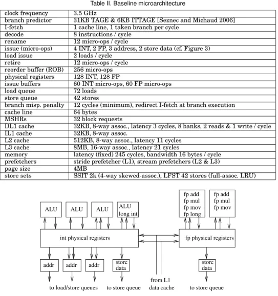
Table II. Baseline microarchitecture
clock frequency 3.5 GHz
branch predictor 31KB TAGE & 6KB ITTAGE [Seznec and Michaud 2006]
I-fetch 1 cache line, 1 taken branch per cycle
decode 8 instructions / cycle
rename 12 micro-ops / cycle
issue (micro-ops) 4 INT, 2 FP, 3 address, 2 store data (cf. Figure 3)
load issue 2 loads / cycle
retire 12 micro-ops / cycle
reorder buffer (ROB) 256 micro-ops
physical registers 128 INT, 128 FP
issue buffers 60 INT micro-ops, 60 FP micro-ops
load queue 72 loads
store queue 42 stores
branch misp. penalty 12 cycles (minimum), redirect I-fetch at branch execution
cache line 64 bytes
MSHRs 32 block requests
DL1 cache 32KB, 8-way assoc., latency 3 cycles, 8 banks, 2 reads & 1 write / cycle
IL1 cache 32KB, 8-way assoc.
L2 cache 512KB, 8-way assoc., latency 11 cycles
L3 cache 8MB, 16-way assoc., latency 21 cycles
memory latency (fixed) 245 cycles, bandwidth 16 bytes / cycle
prefetchers stride prefetcher (L1), stream prefetchers (L2 & L3)
page size 4MB
store sets SSIT 2k (4-way skewed-assoc.), LFST 42 stores (full-assoc. LRU)
data store data store addr addr addr ALU long int
to load/store queues to store queue
fp add fp mul fp mov fp physical registers fp add fp mul fp mov fp long to store queue data cache from L1
ALU ALU ALU
int physical registers
Fig. 3. Baseline out-of-order engine with 8 INT execution ports and 3 FP execution ports. The INT register file has 12 read ports and 6 write ports. The FP register file has 5 read ports and 4 write ports. The issue buffers are not shown.
4.1. Benchmarks
The benchmarks used for this study are the SPEC CPU 2006. They were all compiled with gcc -O2 and executed with the reference inputs. A trace is generated for each benchmark. Each trace consists of about 20 samples stitched together. Each sample represents 50 million executed instructions. The samples are taken every fixed num-ber of instructions and represent the whole benchmark execution. In total, 1 billion instructions are simulated per benchmark.
4.2. Baseline microarchitecture
Our baseline superscalar microarchitecture is representative of current high-end mi-croarchitectures. The main parameters are given in Table II. Several parameters are identical to those of the Intel Haswell microarchitecture, in particular the issue buffer and load/store queues [Intel 2014].
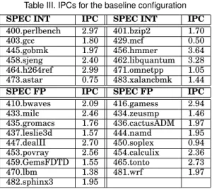
Table III. IPCs for the baseline configuration
SPEC INT IPC SPEC INT IPC
400.perlbench 2.97 401.bzip2 1.70 403.gcc 1.80 429.mcf 0.50 445.gobmk 1.97 456.hmmer 3.64 458.sjeng 2.40 462.libquantum 3.28 464.h264ref 2.99 471.omnetpp 1.05 473.astar 0.75 483.xalancbmk 1.44
SPEC FP IPC SPEC FP IPC
410.bwaves 2.09 416.gamess 2.94 433.milc 2.46 434.zeusmp 1.46 435.gromacs 1.76 436.cactusADM 1.97 437.leslie3d 1.57 444.namd 1.95 447.dealII 2.70 450.soplex 0.94 453.povray 2.56 454.calculix 2.36 459.GemsFDTD 1.55 465.tonto 2.73 470.lbm 1.38 481.wrf 1.97 482.sphinx3 1.95
Macro-fusion is applied to conditional branches when the previous instruction mod-ifies the flags and is of type ALU [Intel 2014]. That is, the two instructions give a single micro-op. Recent Intel processors feature a micro-op cache and a loop buffer [In-tel 2014], which are not simulated here (this study focuses on the out-of-order engine). Instead, we simulate an aggressive front end delivering up to 8 decoded instructions per cycle.
For every memory access, we generate an address micro-op for the address calcula-tion and a store micro-op or a load micro-op for writing or reading the data. The load queue can issue 2 loads per cycle.
The micro-ops have two inputs and one output. Some partial register writes require to read the old register value. When necessary, we introduce an extra micro-op to merge the old value and the new value. Each physical register is extended to hold the flags, which are renamed like architectural registers. A micro-op that only reads the flags, such as a non-fused conditional branch, accesses a read port of the physical register file. Micro-ops that do not write a register or do not update the flags do not reserve a physical register. These include branch, store, and address ops (address micro-ops write in the load/store queues).
Loads are executed speculatively. Load speculations are repaired when a mis-executed instruction is to be retired from the reorder buffer, by flushing the instruction window and re-fetching from the mis-executed instruction. The memory independence predictor is the Store Sets [Chrysos and Emer 1998]. A load can execute speculatively if the most recent store in its store set (the “suspect” store) has been retired from the store queue. A load can also execute speculatively if a matching store queue entry can provide the data to the load and that store is not older than the “suspect” store. The Store Set ID Table (SSIT) is indexed by hashing load/store PCs, using different hashing functions for loads and stores (an x86 instruction may contain both a load and a store). Figure 3 depicts the baseline out-of-order engine. The INT (integer) and FP (floating-point) clusters each have their own issue buffer and scheduling logic. There are 8 INT execution ports and 3 FP execution ports. The execution ports for address micro-ops and store micro-micro-ops do not need a register write port. Instead, they write in the load/store queues. We assume 128 INT and 128 FP physical registers, which is suffi-cient for our single-threaded baseline core. Three INT execution ports are specialized with only one register read port. This saves 3 read ports6. In total, the INT register file
has 12 read ports and 6 write ports. The FP register file has 5 read ports and 4 write ports. The ALU execution ports can execute most INT micro-ops. An execution port is selected for a micro-op before it enters the issue buffer. For load balancing, if several execution ports can execute a given micro-op, the micro-op is put on the execution port that received a micro-op least recently.
5. POTENTIAL IPC GAINS FROM A MORE COMPLEX SUPERSCALAR MICROARCHITECTURE
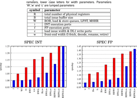
This section studies the impact on IPC of enlarging certain critical parts of the mi-croarchitecture, ignoring implementation issues. The configurations considered in this section are non-clustered microarchitectures. We focus on first-order back-end parame-ters that may have an important impact on IPC. The parameparame-ters are listed in Table IV. Some of the parameters are lumped to limit the configuration space. We include front-end width in the list of parameters as a wider back-front-end generally requires a wider front-end. The 7 parameters of Table IV define 128 non-clustered configurations (in-cluding the baseline), each parameter being either as in the baseline core, or doubled compared to the baseline.
We simulated all 128 configurations and obtained the IPC of each of them. The IPCs for the baseline are displayed in Table III. For all the other configurations, the IPC of each benchmark is normalized to its baseline IPC, that is, only speedups are given
To present our simulation results in a concise way, we use the following method for naming the 128 configurations. Each of the 7 parameters is represented by a unique symbol (see Table IV). The presence of that symbol in a configuration’s name means that the corresponding parameter is twice as large as in the baseline core, otherwise it is dimensioned as the baseline. For instance, configuration ’Bicw’ features INT and FP issue buffers of 120 micro-ops, 16 INT execution ports (the ones shown of Figure 3, duplicated), can issue 4 loads and do 2 writes in the L1 data cache per cycle, can predict 2 taken branches and fetch 2 instruction cache blocks per cycle cycle. Otherwise, it is identical to the baseline.
For summarizing the simulation results, we define configuration classes based on the configuration’s name length. For example, the baseline configuration is in class 0 and configuration ’Bicw’ is in class 4. Then, for each configuration class from 0 to 7, we find the worst (lowest mean speedup) and best (highest mean speedup) configurations in that class.
Figure 4 shows speedups over the baseline for the worst and best configurations in each configuration class, with the configurations’ names indicated. Notice that there is no single bottleneck in the baseline for the SPEC INT, as the best configuration in class 1 yields only +5% sequential performance. For the SPEC INT, the most effective single parameter is the number of INT execution ports. Indeed, the best configuration in class 1 doubles the number of INT execution ports (’i’), and the worst configuration in class 6 is the one without ’i’ (the speedup drops from 1.25 to 1.12).
For the SPEC FP, the most effective single parameter is the number of FP execution ports. Just doubling the number of FP execution ports (’f ’) yields +11% sequential performance on average, and the worst configuration in class 6 is the one without ’f ’ (the speedup drops from 1.41 to 1.20). The other width parameters are not important bottlenecks for the SPEC FP, which are more sensitive to window parameters (physical registers, ROB, etc.).
The extra microarchitecture complexity can be introduced incrementally over sev-eral technology generations. For instance, a first step could be to increase the number of FP execution ports, as this brings significant performance gains on scientific work-loads. Increasing simultaneously the number of INT execution ports, DL1 bandwidth and front-end width could be a second step, which would allow more SMT contexts.
Table IV. Microarchitecture parameters varied in the non-clustered configurations. Upper case letters are for instruction window pa-rameters, lower case letters for width parameters. Parameters ’W’,’w’ and ’c’ are lumped parameters
symbol parameter
R total number of physical registers
B total issue buffer size
W ROB, load & store queues, LFST, MSHR
i INT execution ports
f FP execution ports
c load issue width & DL1 write ports
w front-end width (I-fetch, decode, rename, retire)
SPEC INT SPEC FP
0.95 1.00 1.05 1.10 1.15 1.20 1.25 f i Wf iw BWf icw BWfc Ricw BWfcw RWicw RBWfcw RBWicw RBWifcw speedup 0.95 1.00 1.05 1.10 1.15 1.20 1.25 1.30 1.35 1.40 1.45 w f Bw fc Biw RWf BWiw RBWf BWicw RBWfc
RBWicw RBWifc RBWifcw
speedup
Fig. 4. Speedup over the baseline for the worst and best configuration in each configuration class. The left graph is the geometric mean speedup for the 12 SPEC INT benchmarks, the right graph for the 17 SPEC FP benchmarks. The presence of a letter in a configuration’s name indicates that the corresponding parameter is doubled compared to the baseline (see Table IV).
However, the hardware complexity of the scheduler and bypass network increases quadratically with the issue width [Palacharla et al. 1997], and clustering must be introduced at some point in order not to impact the clock frequency. In the next sec-tion, we quantify the impact of clustering on IPC.
6. DUAL-CLUSTERED CONFIGURATIONS
Section 5 did not take into account the potential impact on the clock cycle. Increasing the number of execution ports while keeping the same clock frequency will require to use clustering at some point. In this section, we study the impact of the inter-cluster delay on IPC, assuming symmetric clustering and register write specialization (cf. Sec-tion 3).
The INT and FP clusters depicted in Figure 3 are duplicated7, which means a total
a 8 ALUs, 6 address generators, and 4 floating-point operators. The INT and FP regis-ters are split in 2 partitions (write specialization). Cluster 0 writes in partition 0 and cluster 1 writes in partition 1. Each partition is implemented with 2 mirror banks, one bank in each cluster. Each cluster has a bank for partition 0 and a bank for partition 1, but writes only in its own partition. Each of the 4 banks has the same number of read and write ports as the register file in the single-cluster baseline (cf. Section 3.4).
7The reason for clustering the FP execution ports is that floating-point operators have a big silicon footprint,
SPEC INTiiffwc (INT) -27 % -24 % -21 % -18 % -15 % -12 % -9 % -6 % -3 % 0 % 3 % 6 % 9 % 12 % 15 % 18 %
ICD=0 ICD=1 ICD=2 ICD=3
cluster 0 Mod-1 Mod-2 Mod-4 Mod-8 Mod-16 Mod-32 Mod-64 Mod-128 Mod-256 ifwc SPEC FPiiffwc (FP) -16 % -12 % -8 % -4 % 0 % 4 % 8 % 12 % 16 %
ICD=0 ICD=1 ICD=2 ICD=3
cluster 0 Mod-1 Mod-2 Mod-4 Mod-8 Mod-16 Mod-32 Mod-64 Mod-128 Mod-256 ifwc
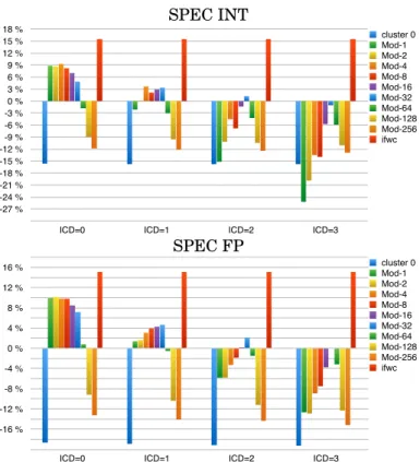
Fig. 5. IPC gain over the baseline for clustered iiffccw configurations, for inter-cluster delays (ICD) of 0,1,2 and 3 cycles, under a Mod-N steering policy with N ranging from 1 to 256. The leftmost bar of each group of bars is the IPC gain when steering all the micro-ops to cluster 0. The rightmost bar is the IPC gain of the non-clustered if cw configuration. The top graph is the average for SPEC INT, the bottom one for SPEC FP. The L1 data cache is banked, with 8 banks interleaved per 8-byte word, like the Intel Sandy Bridge [Intel 2014]. The load queue can issue 4 loads per cycle, instead of 2 in the baseline. Before being entered in the load queue, loads are “steered” to one of the register file partition (a bit in each load queue entry indicates to which partition the load has been steered). There are 2 write ports dedicated to loads in each physical register partition (cf. Figure 1). Each cycle, the load scheduling logic selects the 2 oldest ready loads in each partition.
For the clustered configurations, we assume a DL1 latency of 4 cycles, instead of 3 cycles for the baseline, to take into account the extra complexity of the DL1 cache.
We consider 2 clustered configurations, named using a method similar to the one used in Section 5, except that notation ’iiffcc’ means that the baseline cluster of Figure 3 is duplicated and the issue buffer and physical registers are partitioned:
— iiffccw. Same total instruction window capacity as the baseline (same ROB, same MSHR, etc.), but double front-end bandwidth and dual-cluster backend. Each cluster has an issue buffer partition of 30 micro-ops and a physical register partition of 64 registers.
— RBWiiffccw. Dual cluster back-end, but with the total instruction window capacity doubled: twice bigger ROB, MSHR, load/store queues and LFST, each cluster hav-ing an issue buffer partition of 60 micro-ops and a physical register partition of 128 registers.
SPEC INT RBWiiffwc (INT) -15 % -12 % -9 % -6 % -3 % 0 % 3 % 6 % 9 % 12 % 15 % 18 % 21 % 24 % 27 % 30 %
ICD=0 ICD=1 ICD=2 ICD=3
cluster 0 Mod-1 Mod-2 Mod-4 Mod-8 Mod-16 Mod-32 Mod-64 Mod-128 Mod-256 RBWifwc SPEC FP RBWiiffwc (FP) 0 % 5 % 10 % 15 % 20 % 25 % 30 % 35 % 40 % 45 % 50 %
ICD=0 ICD=1 ICD=2 ICD=3
cluster 0 Mod-1 Mod-2 Mod-4 Mod-8 Mod-16 Mod-32 Mod-64 Mod-128 Mod-256 RBWifwc
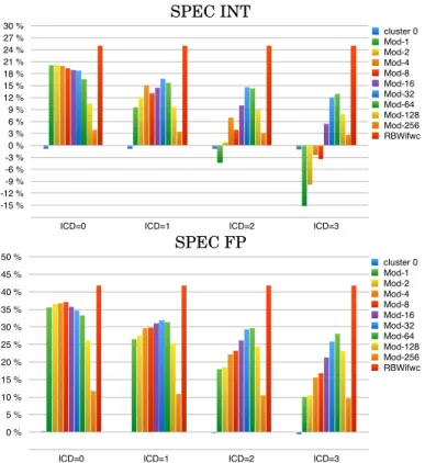
Fig. 6. IPC gain over the baseline for clustered RBWiiffccw configurations (cf. Figure 5).
6.1. Dual-cluster with baseline instruction window size
Figure 5 shows the IPC gain over the baseline for the iiffccw clustered configuration, assuming inter-cluster delays of 0,1,2 and 3 cycles8under a Mod-N steering policy with
N ranging from 1 to 256. Recall that Mod-N steers N x86 instructions (i.e., more than N micro-ops) to a cluster, the next N instructions to the other cluster, and so forth. The leftmost bar of each group of bars in Figure 5 shows the IPC gain when steering all micro-ops to cluster 0.
While the non-clustered configurations showed that it is beneficial to increase the issue width first, and then the instruction window, Figure 5 shows that for the clus-tered configurations the situation is quite different. Indeed, the main conclusion from Figure 5 is that clustering without enlarging the total instruction window does not bring any IPC gain when the inter-cluster delay is 3 cycles. Several factors contribute to this. The increased DL1 latency (from 3 to 4 cycles), the partitioning of the issue buffer and physical registers, the clustering of execution units and load issue ports contribute to decreasing the potential IPC gain, even with a null inter-cluster delay and a Mod-1 steering. But the biggest impact comes from the inter-cluster delay. As the inter-cluster delay increases, the IPC gain drops quickly and eventually becomes an IPC loss, even with the best steering policy (Mod-32 here).
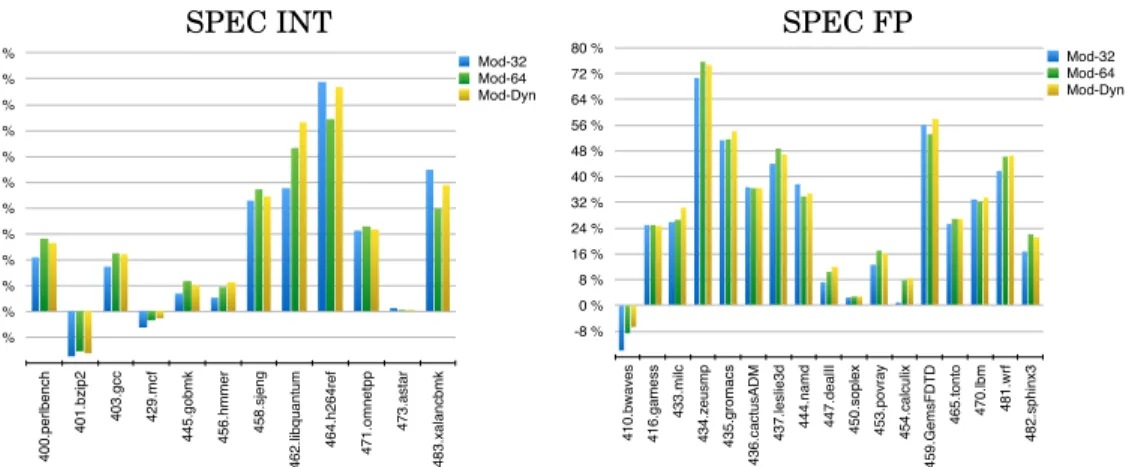
SPEC INT SPEC FP -4 % 0 % 4 % 8 % 12 % 16 % 20 % 24 % 28 % 32 % 36 % 40 % 4 0 0 .p e rl b e n ch 4 0 1 .b zi p 2 4 0 3 .g cc 4 2 9 .mcf 4 4 5 .g o b mk 4 5 6 .h mme r 4 5 8 .sj e n g 462.libquantum 4 6 4 .h 2 6 4 re f 4 7 1 .o mn e tp p 4 7 3 .a st a r 4 8 3 .xa la n cb mk Mod-32 Mod-64 Mod-Dyn -8 % 0 % 8 % 16 % 24 % 32 % 40 % 48 % 56 % 64 % 72 % 80 % 4 1 0 .b w a ve s 4 1 6 .g a me ss 4 3 3 .mi lc 4 3 4 .ze u smp 4 3 5 .g ro ma cs 4 3 6 .ca ct u sAD M 4 3 7 .l e sl ie 3 d 4 4 4 .n a md 447.dealII 450 .so p le x 4 5 3 .p o vra y 4 5 4 .ca lcu lix 4 5 9 .G e msF D T D 465.tonto 470.lbm 4 8 1 .w rf 4 8 2 .sp h in x3 Mod-32 Mod-64 Mod-Dyn
Fig. 7. IPC gain over the baseline for a clustered RBWiiffccw configuration with an inter-cluster delay of 3 cycles: benchmark per benchmark comparison of Mod-32 steering, Mod-64 and adaptive Mod-N.
6.2. Dual-cluster with double instruction window
Figure 6 gives the IPC gain over the baseline for the RBWiiffccw clustered configura-tion. Here, the total instruction window capacity is doubled. In particular, the issue buffer partition and physical register partition of each cluster have the same size as the baseline.
Now, the dual-cluster can outperform the baseline for some Mod-N steering. When steering all micro-ops to cluster 0, the IPC is very close to the baseline, with the impact of the increased DL1 latency more or less compensated by the increased reorder buffer and MSHRs. When the inter-cluster delay is null, Mod-N steering with N ≤ 32 achieves a good ILP balancing. For N > 32 ILP imbalance decreases the IPC. As the inter-cluster delay increases, Mod-N steering with small values of N generates significant IPC drop. With a large N, there are fewer inter-cluster communications and better tolerance to the inter-cluster delay. With an inter-cluster delay of 2 cycles, Mod-64 gives an average IPC gain of +14.3% on the SPEC INT and +29.6% on the SPEC FP. With an inter-cluster delay of 3 cycles, the IPC gain with Mod-64 is still +12.9% and +28.0% on the SPEC INT and SPEC FP respectively.
It can be observed in Figure 6 that when the inter-cluster delay is 2 cycles or more, the IPC is very sensitive to Mod-N steering. Figure 7 shows the IPC gain over the baseline, benchmark per benchmark, for the RBWiiffccw clustered scheme, assuming a 3-cycle inter-cluster delay, comparing Mod-32 and Mod-64 steering. For some bench-marks, Mod-32 outperforms Mod-64. For some other benchmarks it is the other way around.
Baniasadi and Moshovos proposed that, instead of having a fixed Mod-N, we could have an adaptive Mod-N trying to find the best N dynamically [Baniasadi and Moshovos 2000]. We tried an adaptive method similar to Baniasadi’s, trying to identify dynamically the best Mod-N with N in{32, 48, 64, 80, 96}. After having executed 500k micro-ops under Mod-N steering, we try successively Mod-max(32,N-16), Mod-N and Mod-min(96,N+16) for 50k retired micro-ops each, counting the number of cycles. We choose the one with the best local performance, Mod-N’, and run under Mod-N’ for the next 500k micro-ops. We repeat this process periodically, every 500k micro-ops. Results for the adaptive method are shown in Figure 7.
On average, assuming an inter-cluster delay of 3 cycles, the adaptive steering slightly outperforms Mod-64 and Mod-32 and achieves an IPC gain of +14.1% over the baseline for the SPEC INT and +28.8% for the SPEC FP.
4 4 4 4 oldest youngest Mod-‐4 4 = 2 8 − 4 ≈ 0.83 12 − 8 ≈ 0.63 16 − 12 ≈ 0.54 cluster 0: ILP=2.63 cluster 1: ILP=1.37 instruc>on window Mod-‐8 8 8 8 ≈ 2.83 16 − 8 ≈ 1.17 cluster 0: ILP=2.83 cluster 1: ILP=1.17
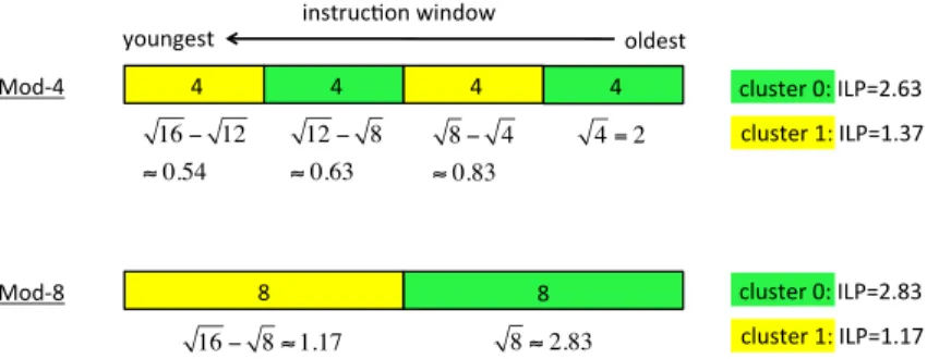
Fig. 8. Illustration of ILP imbalance on 2 clusters, assuming a null inter-cluster delay and assuming the average ILP is the square root of the instruction window size. The upper example is for a Mod-4 steering policy, the lower example for Mod-8. In both examples, the instruction window holds 16 instructions. 6.3. Analysis
Our findings should be contrasted with those of Baniasadi and Moshovos. They found that, among all Mod-N steering policies, Mod-3 was the best policy on average [Bani-asadi and Moshovos 2000]. However they were considering 2-issue clusters.
We first explain with a simple analytical model why Mod-N with a large N is better for wide-issue clusters. Our analytical model is based on the empirical observation that the average ILP is roughly the square-root of the instruction window size [Riseman and Foster 1972; Michaud et al. 2001; Karkhanis and Smith 2004]. We further assume a null inter-cluster delay. The square-root law models the fact that instructions that are ready for execution at a given instant are more likely to be found among the oldest instructions in the instruction window than among the youngest ones. In the example of Figure 8, at the instant considered, the average ILP on cluster 0 is greater than on cluster 1. The ILP imbalance between the 2 clusters increases with the value of N. Because the instantaneous IPC is the minimum of the issue width and the ILP, if the per-cluster issue width is 2 instructions, the IPC on cluster 0 is limited by the issue width, and Mod-4 outperforms Mod-8 (the total IPC is 2+1.37=3.37 with Mod-4 and 2+1.17=3.17 with Mod-8). If we increase the per-cluster issue width to 3 instructions instead of 2, the IPC on cluster 0 is not limited by the issue width, and both Mod-8 and Mod-4 yield the same IPC (hence Mod-8 outperforms Mod-4 if the inter-cluster delay is non null). There is roughly a square relation between the per-cluster issue width and the value of N beyond which ILP imbalance impacts performance significantly. This explains why the optimal N is much greater for wide-issue than for narrow-issue clusters.
To confirm this analysis, we simulated a quad-cluster back-end, each cluster being able to issue and execute 2 ALU or address micro-ops per cycle. The load queue can issue 2 loads per cycle. We assume an issue buffer partition of 15 micro-ops per cluster, so that the total issue buffer capacity is equivalent to the baseline. We assume 128 physical registers, as the baseline, but we removed register write specialization9. The
other microarchitecture parameters are identical to the baseline.
Figure 9 shows the results of this experiment, for the SPEC INT only. When the inter-cluster delay is (unrealistically) null, Mod-N steering with N ≤ 4 achieves a good ILP balancing. The quad-cluster slightly outperforms the baseline thanks to the 8 ALUs (instead of 4 in the baseline). However, for N above 8, ILP imbalance impacts performance significantly because of the small per-cluster issue width.
9Having more architectural registers than physical registers in a cluster partition may lead to deadlocks
-45 % -40 % -35 % -30 % -25 % -20 % -15 % -10 % -5 % 0 % 5 %
ICD=0 ICD=1 ICD=2 ICD=3
Mod-1 Mod-2 Mod-4 Mod-8 Mod-16 Mod-32 Mod-64 Mod-128 Mod-256
Fig. 9. IPC gain over the baseline for a 4-cluster back-end. Each cluster can issue and execute 2 micro-ops per cycle. Only SPEC INT averages are shown.
With an inter-cluster delay of one cycle, as Baniasadi and Moshovos assumed in their study, the trade-off between ILP balancing and inter-cluster communications is at work, and the best steering policy is Mod-2. This is consistent with Baniasadi and Moshovos’ finding that Mod-3 is the best Mod-N policy10. As the inter-cluster delay
increases to 2 and 3 cycles, though, the best N steering becomes 8 and Mod-16 respectively, but the IPC loss is important.
By contrast, with wide-issue clusters, ILP imbalance remains bearable for values of N up to 32-64, as shown in the previous section. As a result, there are few inter-cluster communications, which allows to tolerate longer inter-cluster delays.
6.4. Possible steps toward the proposed dual-cluster configuration
The dual-cluster microarchitecture we described is supposed to be the result of incre-mental microarchitecture modifications over several technology generations. However, going from a non-clustered microarchitecture to a clustered one introduces a perfor-mance discontinuity. Our results show that, to absorb the perforperfor-mance impact of the inter-cluster delay, the instruction window must be large enough. However, clustering is what permits enlarging one of the components of the instruction window: the issue buffer. Yet, we would like an increase of microarchitecture complexity to be rewarded by a performance gain, at least on some applications. The results in Figure 4 suggest a possible path toward the proposed wide-issue dual-cluster configuration:
(1) Introduce clustering for the FP execution units only11.
(2) Enlarge the instruction window, except the issue buffer (reorder buffer, load/store queues, physical registers, MSHRs). This can be done progressively.
(3) When the instruction window is large enough, introduce clustering for the INT execution units and increase the total issue buffer capacity.
The first two steps should benefit applications with characteristics similar to the SPEC FP benchmarks (cf. Figure 4, configuration ’RWf ’).
10For us, the “2” in Mod-2 means two x86 CISC instructions, while Baniasadi and Moshovos considered
RISC instructions.
11Our Mod-64 policy steers to the other FP cluster every 64 general instructions. We did not evaluate the
7. ENERGY CONSIDERATIONS
The energy per instruction (EPI) is likely to be higher in the dual-cluster tecture than in the single-cluster baseline. As explained in Section 2, if the microarchi-tecture is modified incrementally, the microarchitectural EPI increase can be hidden by the energy reductions coming from technology. Nevertheless, we provide in this sec-tion a few research direcsec-tions for tackling the microarchitectural EPI increase. 7.1. Static EPI
The second cluster and larger instruction window substantially increase the back-end static power. The effect on the static EPI, however, is mitigated by the speedup brought by the dual-cluster and the larger instruction window. If the core (including the L2 cache) is powered off during long idle periods, the static EPI depends on the speedup: the higher the speedup, the lower the static EPI. However, not all applications have the same speedup (cf. Figure 7).
For example, let us assume that the L2 cache represents 40% of the baseline core static power, the back-end 40% and the front-end 20%. Moreover, let us assume that the back-end static power of the dual-cluster is twice that of the baseline core, and the front-end static power 30% higher. For example, if the IPC is unchanged, the static EPI is multiplied by 0.4 × 1 + 0.4 × 2 + 0.2 × 1.3) = 1.46. But with a speedup of +20%, the static EPI is multiplied by only 1.46/1.20 = 1.22.
A topic for future research is to find a way to turn the second cluster on and off dynamically depending on the expected speedup.
7.2. Gating inter-cluster communications for reduced dynamic EPI
The dual-cluster microarchitecture has a higher dynamic EPI than the baseline single-cluster. Some of the extra dynamic EPI comes from larger shared structures with a higher bandwidth (DL1 cache, DL1 TLB, load/store queues,...). Inter-cluster communi-cations also contribute to the increased dynamic EPI, in the issue buffer, in the register file and in the bypass network.
If we could identify micro-ops that do not need to forward their result to the other cluster, which we call in-cluster micro-ops, then the result bus segment going out of the cluster could be gated12when these micro-ops executes. Such gating would reduce the
energy spent in the bypass network (charging and discharging the long result buses connecting the clusters) and writing the distant register file bank.
In particular, if the steering policy steers all the micro-ops from the same instruction to the same cluster, a micro-ops that writes a physical register not mapped to an ar-chitectural register produces a value which lives only within the instruction and does not need to be sent to the other cluster.
Roughly, 55% of all the micro-ops executed by the SPEC INT and 65% of all the micro-ops executed by the SPEC FP (compiled with gcc -O2) are micro-ops that produce a value, not counting address computations. On average, about 12% of these micro-ops do not write an architectural register. That is, 12% of the inter-cluster communications can be gated, on average, just by considering these micro-ops.
To identify more in-cluster micro-ops, a possible solution is to add some information in the trace cache (cf. Section 3.7). We assume that all the micro-ops from the same instructions are put in the same trace, and that all the micro-ops in a trace are steered to the same cluster13. If two micro-ops in the same trace write the same architectural
register (write-after-write dependency), the first micro-op is an in-cluster one. So when
12By putting some tri-state buffers in high impedance state, or by clock-gating some latches.
13If a trace contains on average 10 instructions, a policy equivalent to Mod-60 steers 6 traces to a cluster,
Table V. Percentage of values (i.e., not counting addresses) produced by a cluster that do not need to be sent to the other cluster, depending on the trace format
micro-ops/trace in-cluster values
trace format INT FP INT FP
8 micro-ops, 1 branch 5.6 6.6 25 % 32 %
12 micro-ops, 2 branches 10.2 11.1 39 % 42 %
16 micro-ops, 3 branches 14.6 15.2 48 % 49 %
building the trace, in-cluster micro-ops are identified and this information is stored along with the trace in the micro-op cache (one bit per micro-op).
Table V shows the percentage of in-cluster values for various trace formats. As ex-pected, the longer the trace, the more in-cluster values can be identified. For instance, with traces containing about 10 micro-ops on average, about 40% of the values (i.e., not counting addresses) produced by a cluster do not need to be sent to the other cluster, meaning that the corresponding inter-cluster communications can be gated.
Gating some inter-cluster communications requires to keep the physical register file content consistent, as each physical register partition has two copies (one in each clus-ter). When an in-cluster micro-op executes, it writes in its local register bank and up-dates its local scoreboard, but it does not update the distank bank and scoreboard. A branch misprediction can result in an inconsistent state. A possible solution is to retire traces from the reorder buffer only when all the micro-ops in the trace have been ex-ecuted successfully. When a branch misprediction is detected, the in-cluster micro-ops that are before the branch in the same trace are still in the reorder buffer. The branch misprediction recovery logic must find these micro-ops, get their destination physical registers Pi, and inject directly in the local issue buffer some special micro-ops MOV Pi,Pi that send the value of Pi to the distant cluster. These MOV micro-ops execute while the correct-path instructions go through the front-end pipeline stages.
An interesting direction for future research is the possibility to dedicate some execu-tion ports and/or some physical registers to in-cluster micro-ops, which would decrease the hardware complexity of the bypass network and register file [Vajapeyam and Mitra 1997; Rotenberg et al. 1997].
8. RELATED WORK
Several papers have studied steering policies for clustered microarchitectures. Some papers proposed different variants of dependence-based steering policies trying to steer dependent instructions to the same cluster in order to minimize inter-cluster communications, while trying to maintain sufficient load balancing between clusters [Palacharla et al. 1997; Canal et al. 1999; Canal et al. 2000; Fields et al. 2001; Gonz ´alez et al. 2004; Salverda and Zilles 2005]. However, these dependence-based policies are complex, and steering multiple instructions per cycle is an implementation challenge [Salverda and Zilles 2005; Cai et al. 2008].
Baniasadi and Moshovos compared several different steering policies and found that a simple Mod-3 steering policy performs relatively well on their microarchitecture con-figuration (four 2-issue clusters, 1-cycle inter-cluster delay) [Baniasadi and Moshovos 2000].
Zyuban and Kogge proposed clustering as a solution for decreasing the energy per instruction (EPI) for a given IPC [Zyuban and Kogge 2001]. Like us, they considered wide-issue clusters. However, they did not quantify the IPC improvements that clus-tering can provide under a fixed clock cycle.
Trace processors distribute chunks of consecutive instructions (i.e., traces) to the same processing element (PE), like Mod-N steering [Vajapeyam and Mitra 1997; Rotenberg et al. 1997]. Rotenberg observed that the optimal trace size depends on
the PE issue width and that, with 4-issue PEs, 32-instruction traces generally yield higher IPCs than 16-instruction traces [Rotenberg 1999].
To the best of our knowledge, three commercial superscalar processors14have used
clustering: the DEC Alpha 21264 [Kessler 1999] and, recently, the IBM POWER7 and POWER8 [Sinharoy et al. 2011; Sinharoy et al. 2015]. These processors implement narrow-issue clusters with an intercluster delay of one cycle.
The Alpha EV8 processor (canceled in 2001) exploited ILP more aggressively than today’s processors: two 8-instruction blocks fetched per cycle, 8-wide register renam-ing, 8-wide issue, 8 ALUs, 4 floating-point operators, 2 loads + 2 stores per cycle, 512 physical registers with 16 read ports and 8 write ports, a 128-entry issue buffer [Pre-ston et al. 2002], for an aggressive clock cycle equivalent to 12 gate delays [Herrick 2000]. However, only few details about the EV8 microarchitecture were made public.
Some authors have proposed to adjust the per-thread IPC depending on the num-ber of threads by modifying the microarchitecture so that several small cores can be dynamically aggregated into bigger, faster cores [˙Ipek et al. 2007; Boyer et al. 2010]. Eyerman and Eeckhout have argued that similar adaptivity could be obtained with conventional SMT [Eyerman and Eeckhout 2014]. Our proposition of wide-issue su-perscalar core goes in the direction advocated by Eyerman and Eeckhout.
9. CONCLUSION
As the number of cores grows, fewer applications benefit from this growth. Hence se-quential performance is still very important. If the clock frequency remains fixed, as in the last 10 years, the only way to increase sequential performance without recompiling is to increase the IPC. Increasing the IPC significantly likely requires more hardware complexity, in particular a wider issue and a larger instruction window.
At some point, issuing more micro-ops per cycle requires to use clustering. Cluster-ing was introduced and studied at a time when microarchitects were tryCluster-ing to push the clock frequency as high as possible. However, if the clock frequency remains constant, clustering becomes a means to increase the IPC, and our understanding of clustering must be updated.
Unlike most past research on clustered microarchitecture, we consider wide-issue in-stead of narrow-issue clusters. We have shown that, with wide-issue clusters, a simple Mod-64 steering policy tolerates inter-cluster delays of 3 cycles. We have also shown that, in single-thread execution, a significant fraction of the values produced by a clus-ter do not need to be forwarded to the other clusclus-ter. This can be exploited to gate some inter-cluster communications and decrease energy consumption.
The wide-issue dual-cluster configuration that we studied is supposed to be the re-sult of an incremental complexification of the whole microarchitecture over several technology generations. Though clustering solves some key complexity issues in the back end, other parts of the microarchitecture which were not the focus of this study, such as front-end bandwidth and load/store queues, will have to be scaled up too. Some of the solutions that will be needed for these other parts are already known. Some new solutions will probably be needed too.
A. A SIMPLE FORMULA FOR HOT SPOT TEMPERATURE
This appendix provides a simple approximate formula for quickly reasoning about hot spot steady-state temperature in microprocessors15.
14Some commercial VLIW processors also used clustering, e.g., Multiflow [Lowney et al. 1993].
15We provide formula (1) because we are not aware of any reference for it and we believe this formula is
A hot spot can be modeled roughly as a disk heat source of (small) radius r. In what follows, A is the die area, P is the total power dissipation, q = P/A is the average power density, Q is the power density inside the hot spot, Ksi is the thermal conductivity of
silicon, R is the thermal resistance of the die and its packaging (including the heat
sink). We assume that the hot spot is much smaller than the die (πr2 A) and that
the average power density outside of the hot spot is approximately equal to q.
By the principle of superposition [Michaud et al. 2005], the temperature ∆T relative to the ambient at the center of the hot spot can be obtained as ∆Tdie+ ∆Tdisk where
∆Tdieis the temperature contribution of a uniform power density q on the die
∆Tdie= R × q × A
(the temperature contribution of remote heat sources is weakly dependent on their exact location, hence a uniform power density provides a good approximation), and ∆Tdiskis the contribution of a disk heat source of power density Q − q.
∆Tdisk =
1 Ksi
× (Q − q) × r
(see [Thomas 1957] for the temperature of a disk heat source). Hence the temperature of the hot spot (relative to the ambient) is
∆T = R × P + 1
Ksi
× (Q − q) × r (1)
To keep temperature constant, it is sufficient to keep the total power P constant and the power densities Q and q inversely proportional to the hot spot radius r.
REFERENCES
A. Baniasadi and A. Moshovos. 2000. Instruction distribution heuristics for quad-cluster, dynamically-scheduled, superscalar processors. In Proceedings of the International Symposium on Microarchitecture (MICRO).
L. Baugh and C. Zilles. 2006. Decomposing the load-store queue by function for power reduction and scala-bility. IBM Journal of Research and Development 50, 2/3 (March 2006).
G. Blake, R. G. Dreslinski, T. Mudge, and K. Flautner. 2010. Evolution of thread-level parallelism in desktop applications. In Proceedings of the International Symposium on Computer Architecture (ISCA). M. Boyer, D. Tarjan, and K. Skadron. 2010. Federation: boosting per-thread performance of
throughput-oriented manycore architectures. ACM Transactions on Architecture and Code Optimization 7, 4 (Dec. 2010).
Q. Cai, J. M. Codina, J. Gonz ´alez, and A. Gonz ´alez. 2008. A software-hardware hybrid steering mechanism for clustered microarchitectures. In Proceedings of the International Symposium on Parallel and Dis-tributed Processing (IPDPS).
H. W. Cain and M. H. Lipasti. 2004. Memory ordering: a value-based approach. In Proceedings of the Inter-national Symposium on Computer Architecture (ISCA).
R. Canal, J.-M.-Parcerisa, and A. Gonz ´alez. 1999. A cost-effective clustered architecture. In Proceedings of the International Conference on Parallel Architectures and Compilation Techniques (PACT).
R. Canal, J. M. Parcerisa, and A. Gonz ´alez. 2000. Dynamic cluster assignment mechanisms. In Proceedings of the International Symposium on High Performance Computer Architecture (HPCA).
G. Z. Chrysos and J. S. Emer. 1998. Memory dependence prediction using store sets. In Proceedings of the International Symposium on Computer Architecture (ISCA).
S. Curtis, R. J. Murray, and H. Opie. 1999. Multiported bypass cache in a bypass network. US Patent 6000016. (1999).
K. Czechowski, V. W. Lee, E. Grochowski, and R. Ronnen. 2014. Improving the energy efficiency of big cores. In Proceedings of the International Symposium on Computer Architecture (ISCA).
R. H. Dennard, F. H. Gaensslen, H.-N. Yu, V. L. Rideout, E. Bassous, and A. R. LeBlanc. 1974. Design of ion-implanted MOSFET’s with very small physical dimensions. IEEE Journal of Solid-State Circuits SC-9, 5 (Oct. 1974).
H. Esmaeilzadeh, E. Blem, R. St. Amant, K. Sankaralingam, and D. Burger. 2011. Dark silicon and the end of multicore scaling. In Proceedings of the International Symposium on Computer Architecture (ISCA). S. Eyerman and L. Eeckhout. 2014. The benefit of SMT in the multi-core era: flexibility towards degrees of
thread-level parallelism. In Proceedings of International Conference on Architectural Support for Pro-gramming Languages and Operating Systems (ASPLOS).
K. I. Farkas, P. Chow, N. P. Jouppi, and Z. Vranesic. 1997. The Multicluster architecture: reducing cycle time through partitioning. In Proceedings of the International Symposium on Microarchitecture (MICRO). J. A. Farrell and T. C. Fischer. 1998. Issue logic for a 600-MHz out-of-order execution microprocessor. IEEE
Journal of Solid-State Circuits 33, 5 (May 1998), 707–712.
B. Fields, S. Rubin, and R. Bodik. 2001. Focusing processor policies via critical-path prediction. In Proceed-ings of the International Symposium on Computer Architecture (ISCA).
M. Golden, S. Arekapudi, and J. Vinh. 2011. 40-entry unified out-of-order scheduler and integer execution unit for AMD Bulldozer x86-64 core. In IEEE International Solid-State Circuits Conference (ISSCC). A. Gonz ´alez, F. Latorre, and G. Magklis. 2011. Processor microarchitecture. Morgan & Claypool, Chapter 7,
78–90.
J. Gonz ´alez, F. Latorre, and A. Gonz ´alez. 2004. cache organizations for clustered microarchitecture. In Pro-ceedings of the Workshop on Memory Performance Issues (WMPI).
M. Goshima, K. Nishino, Y. Nakashima, S. i. Mori, T. Kitamura, and S. Tomita. 2001. A high-speed dynamic instruction scheduling scheme for superscalar processors. In Proceedings of the International Sympo-sium on Microarchitecture (MICRO).
W. Herrick. 2000. Design Challenges in Multi-GHz Microprocessors. Keynote - Asia and South Pacific Design Automation Conference (ASP-DAC). (2000).
Intel. 2014. Intel 64 and IA-32 architectures optimization reference manual.
E. ˙Ipek, M. Kırman, N. Kırman, and J. F. Mart´ınez. 2007. Core fusion: accommodating software diversity in chip multiprocessors. In Proceedings of the International Symposium on Computer Architecture. ITRS. 2013. International Technology Roadmap for Semiconductors - Process integration, devices, and
struc-tures. (2013). http://www.itrs.net/.
T. S. Karkhanis and J. E. Smith. 2004. A first-order superscalar processor model. In Proceedings of the International Symposium on Computer Architecture (ISCA).
R. E. Kessler. 1999. The Alpha 21264 microprocessor. IEEE Micro (March 1999).
P. G. Lowney, S. M. Freudenberger, T. J. Karzes, W. D. Lichtenstein, R. P. Nix, J. S. O’Donnell, and J. C. Ruttenberg. 1993. The Multiflow trace scheduling compiler. The Journal of Supercomputing 7, 1&2 (May 1993), 51–142.
C.-K. Luk, R. Cohn, R. Muth, H. Patil, A. Klauser, G. Lowney, S. Wallace, V. Janapa Reddi, and K. Hazel-wood. 2005. Pin : building customized program analysis tools with dynamic instrumentation. In Proceed-ings of the ACM SIGPLAN Conference on Programming Language Design and Implementation (PLDI). P. Michaud, Y. Sazeides, A. Seznec, T. Constantinou, and D. fetis. 2005. An analytical model of temperature
in microprocessors. Technical Report RR-5744. Inria.
P. Michaud, A. Seznec, and S. Jourdan. 2001. An exploration of instruction fetch requirement in out-of-order superscalar processors. International Journal of Parallel Programming 29, 1 (Feb. 2001), 35–58. S. Palacharla, N. P. Jouppi, and J. E. Smith. 1997. Complexity-effective superscalar processors. In
Proceed-ings of the International Symposium on Computer Architecture (ISCA).
R.P. Preston, R.W. Badeau, D.W. Bailey, S.L. Bell, L.L. Biro, W.J. Bowhill, D.E. Dever, S. Felix, R. Gam-mack, V. Germini, M.K. Gowan, P. Gronowski, D.B. Jackson, S. Mehta, S.V. Morton, J.D. Pickholtz, M.H. Reilly, and M.J. Smith. 2002. Design of an 8-wide superscalar RISC microprocessor with simultaneous multithreading. In IEEE International Solid-State Circuits Conference (ISSCC).
E. M. Riseman and C. C. Foster. 1972. The inhibition of potential parallelism by conditional jumps. IEEE Trans. Comput. 21, 12 (Dec. 1972).
E. Rotenberg. 1999. Trace Processors: Exploiting Hierarchy and Speculation. Ph.D. Dissertation. University of Wisconsin - Madison. Section 5.3.2.
E. Rotenberg, S. Bennett, and J. E. Smith. 1996. Trace cache: a low latency approach to high bandwidth instruction fetching. In Proceedings of the International Symposium on Microarchitecture (MICRO). E. Rotenberg, Q. Jacobson, Y. Sazeides, and J. E. Smith. 1997. Trace processors. In Proceedings of the
Inter-national Symposium on Microarchitecture (MICRO).
P. Salverda and C. Zilles. 2005. A criticality analysis of clustering in superscalar processors. In Proceedings of the International Symposium on Microarchitecture (MICRO).
A. Seznec, S. Felix, V. Krishnan, and Y. Sazeides. 2002a. Design tradeoffs for the Alpha EV8 conditional branch predictor. In Proceedings of the International Symposium on Computer Architecture (ISCA). A. Seznec and P. Michaud. 2006. A case for (partially) tagged geometric history length branch prediction.
Journal of Instruction Level Parallelism (Feb. 2006).
A. Seznec, E. Toullec, and O. Rochecouste. 2002b. Register write specialization register read specialization: a path to complexity-effective wide-issue superscalar processors. In Proceedings of the International Symposium on Microarchitecture (MICRO).
T. Sha, M. M. K. Martin, and A. Roth. 2005. Scalable store-load forwarding via store queue index prediction. In Proceedings of the International Symposium on Microarchitecture (MICRO).
B. Sinharoy, R. Kalla, W. J. Starke, H. Q. Le, R. Cargnoni, J. A. Van Norstrand, B. J. Ronchetti, J. Stuecheli, J. Leenstra, G. L. Guthrie, D. Q. Nguyen, B. Blaner, C. F. Marino, E. Retter, and P. Williams. 2011. IBM POWER7 multicore server processor. IBM Journal of Research and Development 55, 3 (May 2011). B. Sinharoy, J. A. Van Norstrand, R. J. Eickemeyer, H. Q. Le, J. Leenstra, D. Q. Nguyen, B. Konigsburg, K.
Ward, M. D. Brown, J. E. Moreira, D. Levitan, S. Tung, D. Hrusecky, J. W. Bishop, M. Gschwind, M. Boersma, M. Kroener, M. Kaltenbach, T. Karkhanis, and K. M. Fernsler. 2015. IBM POWER8 processor core microarchitecture. IBM Journal of Research and Development 59, 1 (Jan. 2015).
S. Subramaniam and G. H. Loh. 2006. Fire-and-forget: load/store scheduling with no store queue at all. In Proceedings of the International Symposium on Microarchitecture (MICRO).
P. H. Thomas. 1957. Some conduction problems in the heating of small areas on large solids. Quarterly Journal of Mechanics and Applied Mathematics 10, 4 (1957).
S. Vajapeyam and T. Mitra. 1997. Improving superscalar instruction dispatch and issue by exploiting dy-namic code sequences. In Proceedings of the International Symposium on Computer Architecture (ISCA). V. V. Zyuban and P. M. Kogge. 2001. Inherently lower-power high-performance superscalar architectures.