Abstract—The design and realization of a reconfigurable antenna array operating in the 3.4-3.8 GHz band is presented. Array synthesis methods are developed to reduce the power consumption and are experimentally validated by measurements. The array is composed of 16 dual-polarized dipoles whose excitations are provided by a baseband arbitrary waveform generator. The array is able to radiate simultaneously two or more focused beams in one plane over a scanning range of ±45°, these beams can be reconfigured at will. To achieve these radiation pattern requirements while reducing as much as possible the array power consumption, specific antenna array synthesis tools are developed. In particular, the way to synthesize two sparse arrays at two frequencies having common switched-off antennas is proposed and described. This strategy, together with the synthesis of uniform amplitude excitations, enables to harness the consumption characteristics of power amplifiers. This energy-efficient synthesis means that two mobile operators can share the same antenna array. Several representative measurement results of the array prototype validate the radiation performances and experimentally demonstrate the achieved reduction of power consumption.
Index Terms—Antenna arrays, beamforming, multi-beam antenna, reconfigurable antenna, array synthesis.
I. INTRODUCTION
Phased arrays or active antenna arrays provide beam scanning capabilities that make them attractive for a wide range of applications such as RADAR, tracking and direction finding to name just a few [1], [2]. This technology was first mainly restricted to military applications because of its high cost. Active arrays have more recently been successfully applied to automotive radars [3], [4] and they are now considered as an interesting candidate for 5G communication systems [5], [6].
Active antenna array associated with beamforming has been identified as one of the potential enabling technology for future terrestrial communications [7]. The flexibility brought by smartly combining several antennas allows indeed to focus the beam in a given direction and achieve high data rate and reliable communications, as expected by the future mobile networks [7], [8]. Such a solution is complementary to the increase of
Manuscript received XX. This work was supported by TDF in Liffré, France, and in part by the European Union through the European Regional Development Fund (ERDF), and by the french region of Brittany, Ministry of Higher Education and Research, Rennes Métropole and Conseil Départemental 35, through the CPER Project SOPHIE / STIC& Ondes.
S. Fofana is with the IETR and TDF, Rennes, France. (e-mail: Seydouba.fofana@univ-rennes1.fr).
operating frequency [5], [9] that enables to enhance the bandwidth and achieve even higher data rates.
This paper presents the design of a fully reconfigurable antenna array working in the 3.4 - 3.8 GHz band. This frequency range is considered as a potential candidate for the first 5G services in Europe [10] - [12]. Consequently, this array can be seen as a proof of concept for the future base stations of the 5G terrestrial communications operating in S-band. Indeed, the proposed active array is able to generate simultaneously two or more focused beams at different frequencies, which means that several mobile network operators could share the same antenna. These multiple beams have a scanning range of ±45° and can be reconfigured as desired.
In addition, a special focus is brought on reducing the power consumption of the active array. Because of the inevitable use of several power amplifiers (PA), this point is crucial for the design of base station with beamforming capabilities [13], [14]. For that purpose, a collection of antenna array synthesis tools is proposed and applied not only to comply with predefined radiation pattern templates but also to harness the consumption characteristics of power amplifiers. The array synthesis approaches are formulated as convex optimization problems [15]. Such a formulation has proven to be a good choice to solve array synthesis problem [16]. This is indeed a trade-off between the efficiency of analytical array synthesis techniques and the versatility of global optimization strategies that can get stuck in local minima, as explained in [17][18][19]. The characterization of a fully reconfigurable 16 crossed-dipoles antenna array validates experimentally the radiation performances of the active array prototype and demonstrate the power consumption reduction.
The paper is organized as follows. The antenna array synthesis methods to achieve the radiation performances while reducing the power consumption are detailed in Section II. The prototype of the active and reconfigurable antenna array is described in Section III and experimentally validated in Section IV. Conclusions and perspectives are drawn in Section V.
B. Fuchs, S. Avrillon and F. Colombel are with the Institute of Electronics and Telecommunication of Rennes (IETR), UMR CNRS 6164, University of Rennes 1, Rennes Cedex 35042, France. (e-mail: {benjamin.fuchs;stephane.avrillon;franck.colombel}@univ-rennes1.fr).
L. Lézé and S. Palud are with TDF, Antenna Measurement Center, Les Landais 35340 Liffré, France (e-mail: {laurent.leze;sebastien.palud}@tdf.fr).
Reconfigurable Antenna Array with Reduced Power
Consumption – Synthesis Methods and Experimental
Validations in S-Band
Seydouba Fofana, Benjamin Fuchs, Senior Member, IEEE, Stéphane Avrillon, Franck Colombel,
Laurent Lézé, and Sébastien Palud
II. ANTENNA ARRAY SYNTHESIS
The goal of the antenna array synthesis is to find the excitations feeding the array elements in order to generate a focused beam that respects predefined constraints. After introducing the main notations, the synthesis of focused beam patterns is described. Several synthesis strategies are then proposed to use efficiently the amplifiers and thereby reduce the array power consumption. In addition, the synthesis of robust antenna arrays is addressed in order to design arrays that fit the pattern template despite the inevitable uncertainties encountered when implementing the excitations. Finally, the resolution of these array synthesis problems, that are formulated as convex optimization ones, is discussed.
A. Array Synthesis Formulation
Let us consider an array composed of N antennas located at the positions 𝑟" with n=1,…,N. The problem is described for a
1-D pattern synthesis, i.e. over the azimuthal angle φ in a fixed elevation plane θ=θ0 that is omitted for conciseness. Each
antenna radiates a far field pattern 𝑔" 𝜑 that is simulated or
measured in presence of the other antennas. These so-called embedded element patterns enable to take into account the coupling between antennas [20][21][22]. The electrical far field pattern 𝐸 𝜑 radiated by the antenna array is:
𝐸 𝜑 = 𝐚 𝜑 (𝐱 (1)
with the steering vector
𝐚 𝜑 = 𝑔* 𝜑 𝑒,-./.. 1 … 𝑔4 𝜑 𝑒,-.5.. 1 ( (2)
where 𝐱 is the complex excitation vector of size N, 𝑟 𝜑 is the unit vector in the direction 𝜑, the operator . ( stands for the
Hermitian transposition. Note that the steering vector is computed at a frequency f corresponding to the wavenumber k. The synthesis problem is to find, at the frequency 𝑓7, the
excitation vector 𝐱7 in order to radiate a focused beam in the
direction 𝜑7. This problem can be written as follows:
find 𝐱7 subject to 𝐶7(𝐱7)
with the constraints
𝐶7 𝐱7 =
Re 𝐚7 𝜑IJKL (𝐱7 ≥ 𝛼
max 𝐚𝑨 𝜑 (𝐱7 ≤ TU, for 𝜑 ∉ 𝜑7XYZ[
max 𝐚7 𝜑 (𝐱7 ≤ \T
]^^, for 𝜑 ∈ 𝜑7
`aa
(3)
where 𝜑IJKL, 𝜑7XYZ[ and 𝜑7`aa are the direction of the
maximum radiation, the half power beamwidth (HPBW) region and the sidelobe level region at the frequency 𝑓7, respectively.
The sidelobe level is denoted 𝜌`aa. Note that 𝐚7 is the steering
vector (2) computed at the frequency 𝑓7. In the first constraint
of (3), the real part of the radiated field is set to be greater than a given level to keep the convexity of the problem. This is equivalent to setting a lower bound on the absolute value of the field since the excitations 𝐱7 are determined up to a global
phase shift, see the demonstration in [23]. In addition, the
parameter 𝛼 is the field level radiated by the array at a distance d. This level 𝛼 is linked to the equivalent isotropic radiated power (EIRP) according to the following formula [24]:
α = de∗ghiY
j (4)
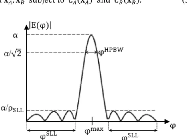
In our study, we want to achieve an EIRP of 48 dBm. The radiation pattern constraints are represented in Fig. 1. A more general synthesis problem is to generate two (or more) different focused beam patterns, each one radiating at a given frequency. In the case of two frequencies 𝑓7 and 𝑓k, the
synthesis problem is:
find 𝐱7, 𝐱k subject to 𝐶7 𝐱7 and 𝐶k 𝐱k . (5)
Fig. 1. Radiation pattern constraints with the associated notations and the angular regions: 𝜑JKL , 𝜑lmm and 𝜑(nko.
B. Array Synthesis for Reduced Power Consumption
The array architecture involves the use of amplifiers (see details in Section III-A). The power consumption of these amplifiers is the main degree of freedom that can be leveraged in order to synthesize an energy-efficient antenna array. For that purpose, three complementary synthesis approaches are proposed.
1) Use of Amplifiers in Linear Regime
The output power of the amplifiers must be below a given level in order to work in their linear regime and avoid distorting the signal. To comply with this requirement, extra constraints can be added to the synthesis problem (4). The maximum power at the output of each amplifier n is bounded as follows:
x",7 𝟐
+ x",k 𝟐
≤ P"JKL (6)
where P"JKL is the 1 dB compression point (P*jZ). The
constraint (6) is added to the ones in (3). It is mandatory in order to synthesize an array that can be implemented.
2) Group-Sparse Arrays
The consumption of the whole active antenna array is logically reduced when some amplifiers are switched-off. The synthesis procedure that minimizes the number of antennas
while complying with a predefined pattern template is known as sparse array synthesis [25], [26].
In our case of interest, the excitation feeding the antenna n should be equal to zero for both frequencies 𝑓7 and 𝑓k in order to be able to switch-off the amplifier n. Therefore, we want to foster the situation where x",7 + x",k = 0 , so as to achieve
a reduction of power consumption. For that purpose, the mixed 𝑙*/𝑙U-norm that enables to promote the sparsity on predefined
groups of excitations is used. Such a structured sparsity is thoroughly described in [27] and has been recently applied to array synthesis problems in [28], [29].
To achieve group-sparsity, we build N groups of two excitations 𝐠"= x",7, x",k for n=1,…,N where x",w is the
complex excitation feeding the antenna n at the frequency 𝑓w
with 𝐾 = 𝐴, 𝐵 . The mixed 𝑙*/𝑙U-norm reads:
𝐠* 𝐠U… 𝐠4 *,U= 4"{* 𝐠" U
= x",7 U+ x",kU
4
"{*
(7) The synthesis problem (5) becomes:
min
𝐱|,𝐱} 𝐠* 𝐠U… 𝐠4 *,U subject to 𝐶7 𝐱7 and 𝐶k(𝐱k) (8)
3) Uniform Amplitude Excitations
There are several benefits in the design of antenna arrays having excitations of the same magnitude. It is indeed easier to tune amplifiers for an optimal efficiency when they all have to deliver the same output power. This is why the synthesis of so-called isophoric array has drawn a lot of attention lately [30].
The minimization of the 𝑙~-norm of a vector x limits the
range of its components x" which then tends to be equal to the
same limit value, i.e. x" = 𝐱 ~, as explained in [29]. We
recall that the 𝑙~-norm of a complex vector x of size N reads:
𝐱 ~= max
"{{*,..,4}x" (9)
Concretely, after applying the group-sparsity (8) described in the previous section, we solve the following synthesis problem for the remaining non-zero excitations denoted 𝐱•:
min
𝐱𝑨,𝐱𝑩 𝐱𝑨 ~+ 𝐱𝑩 ~ subject to 𝐶7 𝐱𝑨 and 𝐶k(𝐱𝑩) (10)
C. Robust Array Synthesis
The radiation performances of an array may be very sensitive to the implementation of its excitations. The synthesis of robust arrays is of uppermost practical interest since it consists in determining the excitation vector 𝐱 such that the array performs well despite potential uncertainties in the realization of the excitations. These uncertainties between the intended excitations 𝐱 and the actual implemented ones 𝐱 can be modeled as follows
x"= x" 1 + 𝛿" with 𝛿" ≤ 𝜌", for 𝑛 = 1, … , 𝑁 (11)
where the complex numbers 𝛿" are the relative errors, as
proposed in [23]. The positive number 𝜌" is the maximum
relative error in implementing x". The uncertainty set is a disk
of radius 𝜌" in the complex plane. As a representative example,
setting the value 𝜌"= 0.1 corresponds approximately to a
maximum magnitude variation of ±0.9 dB and a maximum phase variation of ±6°.
To synthesize robust arrays, we consider the worst case approach introduced in [23]. It amounts to apply the radiation constraints (5) for all excitation vectors 𝐱 (11). We consider the case where all excitations have the same uncertainty (𝜌"= 𝜌, ∀𝑛). After some manipulations (mostly triangular inequalities), the robust synthesis problem can be written:
find 𝐱 subject to 𝐶(𝐱) where the constraints 𝐶(𝐱) are
Re 𝒂 𝜑JKL (𝐱 ≥ 𝛼 + 𝜌 𝐚 𝜑JKL ( . 𝐱 max 𝐚 𝜑 (𝐱 + 𝜌 max 𝐚 𝜑 ( . 𝐱 ≤ T U, for 𝜑 ∉ 𝜑 XYZ[ max 𝐚 𝜑 (𝐱 + 𝜌 max 𝐚 𝜑 ( . 𝐱 ≤ T \]^^, for 𝜑 ∈ 𝜑 `aa (12)
D. Array Synthesis Resolution
All previously described synthesis problems are convex optimization ones [15]. It means that they can be solved very reliably and efficiently for problems having up to a few thousands of unknowns, which is our case of interest. Moreover, a convex formulation implies that the best solution of the problem can be found with a guaranteed convergence at a given accuracy. In case no solution is reached, it means that the synthesis problem does not admit any solution and some constraints must be relaxed. Many convex optimization solvers are readily and freely available. We use the package CVX [31] to specify and solve convex programs.
III. RECONFIGURABLE ANTENNA ARRAY
A reconfigurable array composed of 16 antennas has been designed and manufactured. The array architecture and antenna design are now described.
Fig. 2. Active antenna array architecture composed of a baseband arbitrary waveform generator with 16 channels. Each channel is associated to a mixer with a local oscillator (LO) signal, a power amplifier (PA) and an antenna.
A. Array Architecture
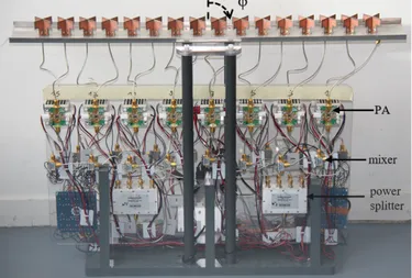
The architecture of the active antenna array is provided in Fig. 2 and the prototype is shown in Fig. 3. We use the arbitrary waveform generator DN6.662-16 of SPECTRUM Instrumentation company [32] to generate 16 signals whose amplitude and phase can be accurately controlled. The generator of sampling rate 625 MS/s is piloted by a computer and can generate 16 signals in baseband from 0 to 200 MHz between ±2.5 V.
These baseband signals are transposed in S-band by the use of 16 mixers [33]. Each mixer requires a signal of frequency 3.57 GHz that is brought by splitting the local oscillator signal (LO) into 16 channels (see the power dividers in Fig. 3).
To generate simultaneously two frequencies, e.g. 𝑓7= 3.58 GHz and 𝑓k= 3.62 GHz, with their own
excitations 𝐱7 and 𝐱k, the baseband signal at the output of the
waveform generator is the sum of 10 and 50 MHz signals, respectively. The bandwidth for each frequency can be set to 20 MHz. A larger bandwidth would enable a more important data transmission capacity but the radiation constraints would be more difficult to respect.
Once in S-band, the signal must be amplified to reach an EIRP of 48 dBm with the antenna array. For that purpose, 16 power amplifiers (denoted PA) are used. We have chosen PA produced by Berex BMT352 [34] because their characteristics match our expectation: a working frequency between 3.4 and 3.8 GHz and an output power of P1dB = 30 dBm.
Fig. 3. Picture of the active antenna array composed of 16 crossed dipoles, power amplifiers and mixers. The five power splitters divide the local oscillator signal. The pattern synthesis is achieved in the azimuthal plane for an angle φ varying from ±90°.
Fig. 4. Measured DC power consumption PDC and efficiency η (=Pout/PDC) of
the BMT352 power amplifier as a function of the output power Pout.
The power consumption and efficiency (η=Pout/PDC) are
measured as a function of the output power, as shown in Fig. 4. The best efficiency is logically achieved for an output power close to P1dB. The bias of each PA has two states (on or off) that
are controlled by computer via switches. As seen in Section II, we want to switch-off as many PA as possible to reduce the power consumption. Moreover, for the PA that are left on, the best efficiency will be reached when they all have the same Pout,
this is the reason why we perform the uniform amplitude excitation synthesis (10). Finally, the outputs of the 16 PA are connected with cables of the same length to the 16 antennas.
B. Antenna Design
The array is made up of 16 antennas. Each antenna is composed of two ±45° crossed dipoles, we consider only one polarization in our investigation. This choice is typical for an array dedicated to base stations in a radio-communication scenario where the antenna must be low cost, easy to manufacture, robust and dual-polarized [35].
The crossed dipoles and the full array have been designed with CST Microwave Studio. As can be seen in the exploded side views of the antenna on Fig.5, the dipole and its balun are each printed on one side of the substrate. The substrate used is Neltec with a thickness of 0.8 mm and a relative permittivity εr = 3. The metallic parts on the substrate are printed in copper
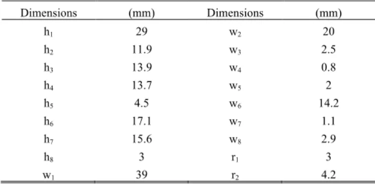
with a thickness of 0.35 µm. The dimensions of the two dipoles are identical except for the baluns and the slot on each of them, enabling them to be crossed. The dimensions are summarized in Table I. The antennas are placed in a U-shaped reflector and spaced by 0.5λ at 3.6 GHz. The U-shaped reflector has a length of 745 mm, a width of 83.33 mm and a height of 9.66 mm.
Fig. 5. Geometry of the ±45° crossed dipoles. The dipole and the balun are printed on opposite sides of the substrate, face 1 and face 2 respectively. The baluns allow to match the feeding port of the dipoles to 50 Ω.
TABLE I
GEOMETRIC PARAMETERS OF THE PRINTED DIPOLES
Dimensions (mm) Dimensions (mm) h1 29 w2 20 h2 11.9 w3 2.5 h3 13.9 w4 0.8 h4 13.7 w5 2 h5 4.5 w6 14.2 h6 17.1 w7 1.1 h7 15.6 w8 2.9 h8 3 r1 3 w1 39 r2 4.2
When embedded in the array, as shown in Fig.6, each dipole must exhibit the following electrical performances: a matching and a mutual coupling below -15 dB over 3.4 – 3.8 GHz band. The Fig. 7 show the electrical performances achieved by a dipole placed in the middle of the array. This result is representative of all dipoles except the one on the edges. We denote: Sii the return loss of the dipole i, Sij the mutual coupling
between the dipole i and its neighbor j and 𝑆,– the coupling
between the two crossed dipoles denoted i and 𝚤.
The antenna array has been manufactured in the IETR workshop and the whole architecture has also been assembled at IETR.
Fig. 6. Close view of the antennas composed of a two crossed dipoles having a ±45° orientation. Each dipole is fed by a connector and fixed to the reflector.
Fig. 7. S-parameters associated to the dipole i located at the middle of the array. The return loss of the dipole i (Sii), the coupling between the two crossed dipoles
(𝑆,–) and the mutual coupling between the dipole i and its neighbor j (Sij). C. Antenna Array Coupling
The coupling between antennas must be carefully taken into account despite the low values of the coupling coefficients between adjacent antennas (|Sij|≤ −15 dB) shown in Fig. 7.
The embedded element patterns have been simulated and measured. They are included in the array synthesis procedure. Moreover, the active reflection coefficient of each antenna Γ šK›œ•žŸ depends on the set of excitations and therefore changes
as the radiated beam is steered [22]. In order to ensure that each antenna remains matched whatever the array radiation configuration, we limit the active reflection coefficient of each antenna by adding the following constraint Γ šK›œ•žŸ ≤ −10 dB
in the synthesis procedure.
IV. EXPERIMENTAL VALIDATIONS
The experimental validation of the antenna array has been carried out in the anechoic chamber of TDF. Two scenarios are considered:
- a single beam with 𝜑JKL= −15° at 3.62 GHz
- two simultaneous beams: 𝜑7JKL= −15° at fA=3.58 GHz
and 𝜑kJKL= 30° at fB=3.62 GHz.
For each beam, the requirements represented in Fig. 1 are: an HPBW 𝜑XYZ[ lower than 10° and sidelobe levels lower than
−15 dB.
The RF channels of our active antenna array have been calibrated using a vector network analyzer to measure the 16 transfer functions and ensure that the desired excitations are feeding the antennas. This calibration step is necessary to compensate for the inevitable differences in amplitude and phase between the 16 outputs induced by the power splitters, power amplifiers, mixers and RF cables.
A. Radiation Performances 1) Single Beam Configuration
We solve the synthesis problem (3) while minimizing the 𝑙*
--norm of the excitations in order to have a sparse array. Two antennas are muted. Then, we solve again the problem (3) by minimizing the 𝑙~-norm (9) so as to achieve excitations with
uniform amplitudes. The synthesized excitations are plotted in Fig. 8a. The phase distribution is not exactly linear in order to
comply with the pattern template despite the uniform amplitude excitations and the two zero excitations.
At this stage, it is important to point out that the coupling between antennas plays a major role. For that reason, the embedded antenna patterns and the output impedances of the PA in state on or off are taken into account in order to model at best the array coupling phenomena. The achieved agreement between the simulated and measured patterns is fairly good for both co- and cross- polarizations, as shown in Fig. 8b. Moreover, the measured cross-polarization level is 17 dB lower than the co-polarization in the main beam.
(a)
(b)
Fig. 8. Synthesis and measurement results of the single beam scenario. (a) Synthesized amplitude and phase distribution. (b) Measured and simulated co- and cross- polarization of the far field radiated by the array at 3.62 GHz.
2) Dual Beam Configuration
We solve here the synthesis problem (8). For both frequencies, the patterns must be respected: a main beam pointing in a predefined direction, an half power beamwidth of at most 10° and sidelobes below -15 dB in the proper angular regions.
Moreover, we minimize the group sparsity of the excitations (7) in order to enforce amplifiers to be switched-off for both frequencies. This step leads to switch-off the amplifier number
2, as shown in Fig. 9a. We then solve the problem (10) to foster the non-zero excitations to have the same magnitude. This goal is almost reached at 3.58 GHz. At 3.62 GHz, a small amplitude taper is required to respect the desired HPBW and steer the beam at the direction +30°.
(a)
(b)
Fig. 9. Synthesis and measurement results of the dual beam scenario. (a) Synthesized excitations with one common switched off amplifier. (b) Measured radiation patterns with simultaneously two beams, one at 3.58 GHz and one at 3.62 GHz. These patterns are normalized with respect to the maximum amplitude achieved at 3.62 GHz.
3) Summary and Discussion
The simulated and measured radiation performances of both configurations are summarized in Table II. The achieved EIRP values are always lower than the expected 48 dBm because the output impedances of the PA were not considered in the synthesis procedure when optimizing the array excitations. Not including the active element patterns has led to an overestimation of the EIRP. The values of the simulated EIRP in Table II are computed considering the active element patterns with the implemented excitations. This phenomenon is all the more true in presence of switched-off PA that exhibit different output impedance. For the cases, not shown in the paper, where all PA are switched-on, the agreement between simulation and measurements is excellent. Besides, the realized excitation distribution does not exactly match the synthesized ones because of inevitable circuitry and manufacturing uncertainties. This also yields differences between simulation and measurements. To overcome the latter issue and render the radiated field less sensitive to the synthesized excitations, a robust synthesis approach has been proposed in Section II-C.
TABLE II
RADIATION PERFORMANCES OF THE ACTIVE ANTENNA ARRAY
Frequency (GHz) Angle 𝜑JKL Simulated EIRP (dBm) Measured EIRP (dBm) fA=3.62 -15° 46.6 46.1 fA=3.58 -15° 47.3 46.6 fB=3.62 +30° 47.6 46.9
B. Reduction of Power Consumption
We compare the power distribution, i.e. the power Pout at the
16 outputs of the PA, for two types of antenna arrays. The first type, called sparse and uniform amplitude, is achieved by solving (3) with a 𝑙*-norm minimization of the excitations and (3) with a 𝑙~-norm minimization (9). The second array type, denoted tapered, is synthesized solving simply (3).
The output power distribution for both array types are plotted in Fig. 10a and 10b, when the beam is steered in -15° and -45°, respectively.
(a)
(b)
Fig. 10. Output power distribution Pout at 3.62 GHz for two arrays (sparse uniform
and tapered) for a main beam pointing at (a) -15° and (b) -45°.
The measured power consumptions are compared in Table III for various configurations. The beam configurations 𝜑JKL= −15° and 𝜑JKL= −45° correspond to the pattern
shown in Fig. 10a and 10b, respectively. As expected, when more PA are switched-off, the power consumption reduction is greater. The scenario 𝜑JKL= 0° has 3 switched-off PA and
yields a 10 % reduction of the power consumption with respect to a tapered array type.
The case of a large beam steering angle (𝜑JKL= -45°) is also
considered. We compare the uniform amplitude with the tapered approach. We notice that only a very small reduction of
the power consumption is achieved thanks to the uniform excitation. However, the uniform excitation could be further leveraged with variable bias tensions. In that case, the bias could be tuned to make all PA work in the region where their efficiency is better.
Furthermore, it is important to point out that a lower EIRP leads to more switched-off PA and therefore a greater reduction of the power consumption, as shown in Table IV. Consequently, the choice of the PA, and specifically their 1 dB compression point P1dB, is crucial in order to achieve a desired
EIRP while reducing the power consumption. Indeed, the value P1dB must be high enough to be able to switch-off some PA but
not too high in order to use the PA in their linear and efficient regime.
To sum up, the reduction of power consumption is logically tightly linked to both the radiation specifications and the characteristics of the PAs used in the array. It means that larger reductions of the power consumption could be achieved using the proposed array synthesis methodology.
TABLE III
POWER CONSUMPTION OF THE AMPLIFIERS FOR VARIOUS CONFIGURATIONS
Freq. (GHz) Array type 𝜑JKL P DC (W) Switched -off PA Power consumption reduction 3.58 Sparse uniform 0° 27.3 3 10 % Tapered 30.2 0 3.62 Sparse uniform -15° 27.1 2 6 % Tapered 28.8 0 3.62 Sparse uniform +30° 28.3 2 4 % Tapered 29.5 0 3.62 Uniform -45° 30.4 0 1 % Tapered 30.7 0 TABLE IV
RELATION BETWEEN EIRP AND POWER CONSUMPTION
(𝜑¡¢£= −15 ° AT 3.62GHZ, WITH SPARSE UNIFORM ARRAY TYPE) Desired EIRP (dBm) Switched-off PA Measured PDC (W)
42 5 19
48 2 27.1
V. CONCLUSION
The prototype of a reconfigurable antenna array operating in S-band (3.4-3.8 GHz) has been presented and experimentally validated. The active array is composed of 16 dual-polarized dipoles that can radiate a focused beam-pattern steerable in one plane for angles ranging between ±45°. Moreover, thanks to the use of an arbitrary waveform generator, two focused beams pointing in two directions at two different frequencies can be generated simultaneously and steered independently at will. The design of this active array has been driven by the reduction of the power consumption. Antenna array synthesis tools have been developed to leverage at best the power consumption characteristics of the amplifiers. These tools have been experimentally validated, demonstrating their practical
relevance and ability to handle with the coupling between antennas. Moreover, the reduction of power consumption has been measured in a number of representative configurations.
This fully reconfigurable array calls for further promising extensions that are left for future works. Indeed, without any change of the active array architecture, several features of practical relevance could be achieved. For instance, other types of radiation patterns, e.g. sectorial or cosecant patterns, could be generated. More than two frequency bands together with their associated beams could be simultaneously generated. Finally, the transmission of a modulated signal instead of a single frequency would also be of interest.
ACKNOWLEDGMENT
The authors would like to thank Frédéric Boutet and Christophe Guitton for their important help to build and assemble the antenna prototype.
REFERENCES
[1] R. J. Mailloux, “Phased array theory and technology,” Proc. IEEE, vol. 70, no. 3, pp. 246–291, Mar. 1982.
[2] E. Brookner, “Phased array radars-past, present and future,” in Proc. RADAR, Oct. 2002, pp. 104–113.
[3] J. Hasch, E. Topak, R. Schnabel, T. Zwick, R. Weigel, C. Waldschmidt, “Millimeter-wave technology for automotive radar sensors in the 77 GHz frequency band,” IEEE Trans. Microw. Theory Techn., vol. 60, no. 3, pp. 845-860, 2012.
[4] J. Xu, W. Hong, H. Zhang, G. Wang, Y. Yu, and Z. H. Jiang, “An array antenna for both long- and medium-range 77 GHz automotive radar applications,” IEEE Trans. Antennas Propag., vol. 65, no. 12, pp. 7207– 7216, Dec. 2017.
[5] R. Schulpen, U. Johannsen, S.C. Pires, A.B. Smolders, “Design of a Phased-Array Antenna for 5G Base Station Applications in the 3.4-3.8 GHz Band,” European conference on Antennas and Propag. (EuCAP), Apr. 2018.
[6] P. Sanchez-Olivares and al, “Circular Conformal Array Antenna with Omnidirectional and Beamsteering Capabilities for 5G Communications in the 3.5-GHz Range,” IEEE Antennas and Propag. Magazine, Aug. 2019.
[7] S. Mohammad Razavizadeh, M. Ahn and I. Lee, “Three-Dimensional Beamforming: A new enabling technology for 5G wireless networks,” IEEE Signal Proc. Mag., vol. 31, no. 6, pp. 94-101, Nov. 2014. [8] E. Dahlman, and al, “5G wireless access: requirements and realization,”
IEEE Commun. Mag., vol. 52, no. 12, pp. 42–47, Dec. 2014.
[9] W. Roh and al, “Millimeter-wave Beamforming as an Enabling Technology for 5G Cellular Communications: Theoretical Feasibility and Prototype Results,” IEEE Communication Mag., vol. 58, Feb. 2014. [10] European Commission, “Radio spectrum policy group strategic roadmap
towards 5G for Europe,” Nov. 2016.
[11] GSM Association (GSMA), “Considerations for the 3.5 GHz IMT range: Getting ready for use,” May 2017.
[12] Federal Ministry of Transport and Digital Infrastructure, “5G strategy for Germany,” Sept. 14, 2017. [Online]. Available: https://www.bmvi.de/Shared-Docs/EN/publications/5g-strategy-for-germany.pdf
[13] M. H. Alsharif, M. Ismail and R. Nordin, “Survey of Green Radio Communications Networks: Techniques and Recent,” Journal of Computer Networks and Communications, Dec. 2013.
[14] S. K. Bhondge, D. B. Bhoyar and S. Mohad, “Strategy for Power Consumption Management at Base Transceiver Station,” IEEE Word Conference on Futuristic Trends in Research and Innovation for Social Welfare, 2016.
[15] S. Boyd and L. Vandenberghe, Convex Optimization. Cambridge, U.K.: Cambridge Univ. Press, 2004.
[16] H. Lebret and S. Boyd, "Antenna pattern synthesis via convex optimization," IEEE Trans. Signal Processing, vol. 45, no. 3, pp.526-531, March 1997.
[17] T. Isernia, F. J. Ares Pena, O. M. Bucci, M. D'Urso, J. F. Gomez, and J. Rodriguez, "A hybrid Approach for the Optimal Synthesis of Pencil Beams Through Array Antennas," IEEE Trans. Ant. Propag., vol.52, pp. 2912-2918, 2004.
[18] M. D'Urso and T. Isernia, "Solving some array synthesis problems by means of an effective hybrid approach," IEEE Trans. Ant. Propag., vol. 55, pp. 750-759, March 2007.
[19] M. D'Urso, T. Isernia and F. Meliado, "An effective hybrid approach for the optimal synthesis of monopulse antennas," IEEE Trans. Ant. Propag., vol. 55, pp. 1059-1066, April 2007.
[20] D. F. Kelley and W. L. Stutzman, “Array antenna pattern modeling methods that include mutual coupling effects,” IEEE Trans. Antennas Propag., vol. 41, no 112, p. 1625–1632, Dec. 1993.
[21] D. M. Pozar, “The active element pattern,” IEEE Trans. Antennas Propag., vol. 42, no 18, p. 1176–1178, Aug. 1994.
[22] D. M. Pozar, “A relation between the active input impedance and the active element pattern of a phased array,” IEEE Trans. Antennas Propag., vol. 51, no. 9, pp. 2486–2489, Sep. 2003.
[23] A. Mutapcic, S.-J. Kim, and S. Boyd, “Beamforming with uncertain weights,” IEEE Signal Proc. Let., vol. 14, p. 348–351, May 2007. [24] T. A. Milligan, Modern Antennas Design, A JOHN WILEY & SONS,
2nd ed., 2005.
[25] G. Prisco and M. D’Urso, “Maximally sparse arrays via sequential convex optimizations,” IEEE Antennas Wirel. Propag. Let., vol. 11, p. 192–195, 2012.
[26] B. Fuchs, “Synthesis of sparse arrays with focused or shaped beampattern via sequential convex optimizations,” IEEE Trans. Antennas Propag., vol. 60, 17, p. 3499–3503, Jul. 2012.
[27] F. Bach, R. Jenatton, J. Mairal, and G. Obozinski, “Optimization with sparsity-inducing penalties,” Found. Trends Mach. Learn., vol. 4, no. 1, pp. 1–106, Jan. 2012.
[28] O. Mehanna, N. Sidiropoulos, and G. Giannakis, “Joint multicast beam-forming and antenna selection,” Trans. on Signal Proc., vol. 61, p. 2660– 2674, May 2013.
[29] B. Fuchs and S. Rondineau, “Array pattern synthesis with excitation control via norm minimization,” Trans. on Antennas and Propag., vol. 64, no 110, p. 4228–4234, Oct. 2016.
[30] O. M. Bucci, M. D’Urso, T. Isernia, P. Angeletti, and G. Toso, “Deterministic synthesis of uniform amplitude sparse arrays via new density taper techniques,” Trans. on Antennas and Propag., vol. 58, no16, p. 1949–1958, June 2010.
[31] CVX Research, Inc. (Sep. 2012). CVX: Matlab Software for Disciplined Convex Programming, Version 2.0 Beta. Available: http://cvxr.com/cvx. [32] Spectrum, 16 bit Arbitrary Waveform Generator, Available:
https://spectrum-instrumentation.com/en/dn6662-16 .
[33] Mini-Circuits, Double Balanced Mixer: RF/LO Freq 2300 –7600 MHz, Available:
https://www.minicircuits.com/WebStore/dashboard.html?model=ZX05-762H-S%2B.
[34] BEREX, High Power Amplifier, Available: https://www.berex.com/Products/HighPowerAmplifier.aspx.
[35] Z. N. Chen and K.-M. Luk, Antennas for base stations in wireless communications, The McGraw-Hill Companies, 2009.