HAL Id: hal-01555713
https://hal.archives-ouvertes.fr/hal-01555713
Submitted on 4 Jul 2017HAL is a multi-disciplinary open access archive for the deposit and dissemination of sci-entific research documents, whether they are pub-lished or not. The documents may come from teaching and research institutions in France or abroad, or from public or private research centers.
L’archive ouverte pluridisciplinaire HAL, est destinée au dépôt et à la diffusion de documents scientifiques de niveau recherche, publiés ou non, émanant des établissements d’enseignement et de recherche français ou étrangers, des laboratoires publics ou privés.
Collision Target Detection Using a Single Antenna for
Automotive RADAR
Souleymane Abakar Issakha, Francois Vincent, Laurent Ferro-Famil, Frantz
Bodereau
To cite this version:
Souleymane Abakar Issakha, Francois Vincent, Laurent Ferro-Famil, Frantz Bodereau. Collision Tar-get Detection Using a Single Antenna for Automotive RADAR . International Radar Symposium (IRS) 2017, Jun 2017, Prague, Czech Republic. �hal-01555713�
The 18th International Radar Symposium IRS 2017, June 28-30, 2017, Prague, Czech Republic
978-3-7369-9343-3 ©2017 DGON 1
Collision Target Detection Using a Single Antenna for Automotive
RADAR
S. ABAKAR ISSAKHA *, F. VINCENT**, L. FERRO-FAMIL***, F. BODEREAU*
*ZF-TRW AUTOCRUISE SAS, Brest, FRANCE
email: {Souleymane.Abakarissakha; Frantz.Bodereau}@zf.com
**University of Toulouse, France
email: [email protected]
***University of Rennes1, France
email: [email protected]
Abstract: The goal of most modern automotive safety driver assistance functions is to avoid possible collisions. Pedestrian protection, predictive emergency braking or turn and crossing assist functions are usually based on two steps. First, the radar provides detailed information on the environment, and then a detection procedure is driven. Because of the complicated environment near the vehicle, this second step is a difficult task to achieve in order to give reliable information to the driver. In this paper, we propose to fuse the environment estimation and the detection step into a simple and direct collision target detector. Indeed, this procedure allows detecting possible collision targets, based on their typical Doppler signature, while rejecting all fixed and non-dangerous targets (clutter). Moreover, this detector only exploits a single antenna, and the necessary target speed vector information is obtained by a second order phase expansion using a long integration time, making the use of an antenna array unnecessary.
1. Introduction
Among the different kinds of sensors developed to improve vehicle safety and autonomy, radar appears to be a solution of choice because of its all-weather operating capability [1]. In addition, radar systems are easy to integrate on a car as they can be installed behind the bumpers [2]. With new Euro-NCAP procedures now requiring automated braking and pedestrian safety functionality, modern Advance Driver Assistance Systems (ADAS) need to give precise and reliable environment information. The common scheme to achieve such a collision detection system is performed in two steps. First, the radar provides a high resolution range, speed and Direction of Arrival (DoA) map and then a detection step is performed to alert the driver of any possible collision. This last decision step is not an easy task because of the complicated environment surrounding the vehicle.
In this paper, we propose to adapt a collision detection procedure developed for airborne radar in [3] to the specific case of automotive sensing and we propose an optimal processing architecture. This detector exploits a long integration time to improve the speed vector estimation. Hence, as it is done in Synthetic Aperture Radar (SAR), and using a second order expansion of the received signal phase, one can both estimate the radial and orthogonal, i.e. tangent, velocity vector components [3]. It is then possible to discriminate dangerous targets from the others. Indeed, all collision targets have a null orthogonal velocity component, with respect to the radar as opposite to non-dangerous targets whose orthogonal velocity is linked to their radial speed and angular position.
A matched detector can be developed in order to detect only collision targets while rejecting the main part of the clutter, i.e. the one having a non-null orthogonal velocity component. This procedure allows fusing all the processing steps into a single one but above all, only
2
requires a single antenna as opposite to most advanced systems requiring an antenna array to estimate the DoA. This direct collision target detection procedure can then allow developing low-cost ADAS systems.
This paper is organized as follows. Section 2 introduces the data model used to define the collision and interference subspaces. Then, in section 3, the detector is developed and simulation results are presented in section 4. Section 5 describes theoretical performances and finally, a possible processing architecture is given in section 6.
2. Data Model
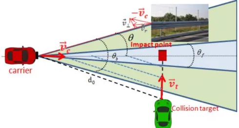
An automotive radar system moving at constant velocity v is considered, as shown on Fig. 1. c
A possible collision target at range d with constant velocity 0 v is heading toward the car up t
to an impact point. Other static targets are also present at the same range d . 0
Figure 1: Static targets and collision target at range d0
For a target located at a sufficiently large distance from the radar, the target-radar distance may be approximated using a second order Taylor series expansion as [3]:
(1)
where d is the initial position of the target, 0 v and r a are respectively the relative radial r
velocity and acceleration, and v is the orthogonal velocity of the target. In this paper, we ⊥
only consider constant radial velocities, i.e.ar =0.
Among all possible values of v and r v , collision targets and non-dangerous ones belong to ⊥
different subspaces. Indeed, on may discriminate the following categories of targets
Static targets (clutter), whose two components of the relative speed vector may be written as a function of the car velocity v and of the target angular position c θ as
θ
cos
c r v
v =− and v⊥ =−vcsin
θ
. Collision targets, characterized by v⊥ =0, with an angular position that remains
constant as the radar moves. One may remark that static targets located at θ= 0°, i.e.
right in front of the car are indeed correctly considered as collision targets. Moving, but non-dangerous targets, with vt,v⊥ ≠0
2 0 2 0 2 1 t d v a t v d t d( ) r r . + + + ≈ ⊥
3
The radar considered here periodically emits and receives signal, with a Pulse Repeat Interval (PRI) T , whose focusing in distance leads to a mapping of the scene reflectivity with a given r
range resolution δd. Assuming a sufficiently large range resolution value or a priori
compensation of range cell migrations, the range focused response of a moving target contained within a range resolution cell may be written, using the phase model expressed in (1) and for an arbitrary pulse occurrence m as:
(
)
,
0
m
M
1
α
(m)
=
e
+ + 2with
≤
≤
−
r 2 2 r 1 0 amT amT a js
(2)where
α
is the target complex response after range focusing,λ
π 0
0
4 d
a = , with λ the carrier wavelength, a vr πfD
λ
π 2
4
1 = = is the slope of the linear phase rotation due to vr and may be related to Doppler frequency fD,
0 2 2 2 d v a λπ ⊥
= is the quadratic term coefficient due to v⊥. Hence for long enough integration time(M −1)Tr, the term a2 can be exploited to estimate the target orthogonal velocityv⊥. Given this model, two different subspaces may be constructed based on the speed characteristics stated before.
- The Collision Target Subspace:
As seen before, a collision target is characterized by a null orthogonal speed component, i.e.,
0
2 =
a . As a consequence, after range processing, the signal sampled over M PRIs, within a given resolution cell, and originating from a potential collision target can be written as follows:
∈ =h(a1)α
x
ℂ
M×1 (3)where
a
1 andα
are unknown, andh
(a
1)
=
[1,e
ja1Tr,...,e
ja1(M−1)Tr]
T is the target Dopplerphase evolution, that is a pure tone (without second order phase rotation).
- The Static Target Subspace:
As stated previously, static targets have radial and orthogonal velocity components that depend on the radar velocity and on their angular position. Hence, the clutter presents in a range cell located at a distance d0 from the radar may be represented by a sum of components having random complex responses and following a given phase model:
c = Sβ (4) where β∈
ℂ
P×1 represents the corresponding complex and unknown responses of thescattering that compose the clutter, and S =
[
s1...sP]
∈ℂ
M×P with( ) ( )
[
j a v M T a v M T]
T p r p c r p c e ( 1 , ( 1) 2 , ( 1)2 2) , , 1 − + − = θ θs the corresponding signature characterized by
(
θ)
π cλ θp p c v v a1 , = 4 cos and(
)
(
)
0 2 ² sin 2 , d v v a c p c p λ θ π θ = .The angular position at which is observed a scatterer belongs to a domain whose limits are fixed by the scattering pattern of the radar antenna, i.e. |θp|≤ . θb
4
3. Matched Detector
A classical way to state the collision target detection problem is based on the following binary hypothesis test [4]:
(5) whose Maximum Likelihood leads to the so called matched detector, when the noise term b is assumed to follow a Gaussian distribution and to be white in time, with a known power:
η > < =yHPhy MD T (6) where h h hh Ph H H
= is the projection matrix onto the signal subspace and . the conjugate H transpose operator.
As h is a pure tone, it is straightforward to show that this detector simply consists in the square modulus of the Fourier transform of the data.
Nevertheless, the restriction of the nuisance terms to a Gaussian white noise leading to the previous matched detector may be considered as a very strong hypothesis. To be more precise, we can decompose the interference term into a clutter part, whose response model is mentioned above, and a Gaussian white background noisen. Moreover, as seen before, the Doppler signature of the clutter is significantly different from that of a collision target, and this difference may be used to further discriminate these types of contribution, leading to a modified binary hypothesis test [5]:
+ + = + = n Sβ h y : n Sβ y : α H H 1 0 (7) However, even if the Doppler signatures of the clutter and target subspaces are different, they overlap in the front region of the radar, as the orthogonal speed of the clutter tends to zero. In other words, in front of the radar, the clutter becomes a collision target too. To prevent a possible ambiguity, we limit the clutter subspace to the side-regions from the radar. Hence, the column of S are constructed from angular positions
θ
pbelonging to [−θb −θf] and]
[θf θb , where θf corresponds to a blanking angle. This minimum angle needed to distinguish a static target from a collision one can be estimated from the second order phase expension term as it is the difference between the phase signatures of collision and static targets: 2 0 2 2 . sin 2 t d vc p
λ
θ
π
ϕ
= Δ (8) The minimum blanking angle valueθ
f is chosen so that the quadratic phase term in (8) equals2 . For such a value, it is expected that the two signatures may be separable (by a π correlation processing, for instance). The minimum angle needed to dissociate the two subspaces is then defined as: = − 2 0 1 2 sin D d f
λ
θ
(9) where D=vc(
M −1)
Tr is the synthetic antenna size. + = = b h y : b y :
α
1 0 H H5 It can be noticed that this minimum angle is inversely proportional to the square of the synthetic antenna size, and also depends on range. Fig. 2 shows the evolution of this minimum angle as a function of the target range for different synthetic antenna sizes and for a radar operating at77GHz. Obviously, the longer the antenna size, the better the subspace separation with a price to be paid for this improvement represented by a longer detection duration and possibly incompatible with the safety and braking requirements. Nevertheless, from Fig. 2, we can see that D 2= m offers a good compromise, as it corresponds to a displacement of half a standard car length (or a signal duration of 144msfor vc =50km/h) which seems to be compatible with warning alerts, while limiting the minimum angle for separation to 10 for ranges up to ° 50 . m
Figure 2: Minimum Angle to separate a collision target from the clutter
Now, based on the modified binary hypothesis test from (7), and assuming that n is a white gaussian noise with known variance, we can calculate the corresponding Generalized Likelihood Ratio Test (GLRT) [4][5]:
γ
> < ′ ′ ′ =y HPhy MMD T (10) where y′=PS⊥y and h P h S⊥ =′ are the projections of the data and target signature onto the subspace orthogonal to the clutter subspaceP I S
( )
SHS SHS
1 −
⊥ = − .
Once again, the proposed processing consists in a modified Fourier transform as both the data and the target signature have to be projected onto the subspace orthogonal to the clutter before to be correlated.
4. Simulation Results
The goal of this part is to exhibit the superiority of the proposed detection scheme compared to the classical Doppler based one, on a simple example. We consider a waveform with a carrier frequency of f0 =77GHz, a bandwidth of B0 =75MHz and a PRI of Tr =115
μ
s. In this scenario, we consider that the radar is moving atvc =50km/h, and a collision target approaching perpendicularly at vt =15km/h from an initial position characterized by6
m
d0 =20 andθ = 30°, as indicated on Fig. 1. The clutter is also at d0 =20m with a clutter to noise ratio ofCNR=15dB. The Signal to Clutter plus Noise Ratio is SCNR=−10dB . We consider an integration time of 144ms corresponding to a synthetic antenna size ofD 2= m. As stated before, the classical and proposed detection schemes correspond to Fourier or modified Fourier transforms. Fig. 3 represents the corresponding test values for each Doppler frequency hypothesis. We can see that the classical Doppler processing cannot detect the collision target as its Doppler response is drown into the clutter one. On the other hand, the proposed detection scheme allows to clearly detect the target.
(a) FFT before detector (b) FFT after detector
Figure 3: Doppler frequency before and after target detector
5. Theoretical Performances
This part aims at comparing the theoretical performances of the proposed detector compared to the classical Doppler-based one. To this end, we calculate the Probability of Detection (PD) of each detector for a given Probability of False Alarm (PFA), varying the Signal to Clutter plus Noise Ratio (SCNR).
The two detectors having the same form, it is straightforward to show that they are chi-squared distributed under each hypothesis [5] [7] [8] [9] [10]:
( )
( )
( )
0 2 2 1 2 under 0 under : y H H T p 1 p MD χ δ χ and( )
( )
( )
0 2 2 2 2 under 0 under : y H H T p 1 p MMD χ δ χ (11) where 2( )
0 pχ
is the central chi-square distribution,( )
2 1 2δ
χ
p andχ
2p( )
δ
22 are the noncentralchi-square distributions, p is the number of degree of freedom, 2
1 2 1 2 1 σ μ δ = and = hTPS⊥h 2 2 2 2 2 2 σ μ δ
are noncentrality parameters, wih
μ
1andμ
2 are respectivly the mean of signals due to (5) and (7), 21
σ and 2
2
σ are respectivly the variannce due to (5) and (7), hTPS⊥his the processing loss
due to the oblique projection.
Hence for a given PFA(for example =10−6
FA
P ) we can compute the corresponding thresholds using following relations:
[
T H0]
P
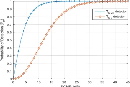
7 Then the Probabilities of Detection PDcan be computed. Fig. 4 shows that the PD of the proposed detector is largely better than the classical detector for all SCNR values.
Figure 4: Probability of detection versus SCNR before and after detector
6. Processing Architecture
Based on the previous analysis, we can now propose a possible processing architecture for the collision target detector on Fig. 5. As stated before, to maintain a synthetic antenna length of
m
D 2= , we have to adapt the integration time to the vehicle speed v . Moreover, for c simplicity considerations, we have chosen a limited bandwidth of B0 =75MHz compatible with the Doppler processing without range migration compensation. ForD 2= m,Tr =115
μ
s,h km
vc =50 / and d0 =20m, we can set some parameters such as: the integration time ms v D T c 144 = =
int , the corresponding number of ramps = =1252
r cT v
D
M and the blanking
angle θf = 665. °.
Figure 5: Simplified architecture for the proposed Automotive Collision Detector
7. Conclusion
In this paper, we have adapted a collision target detector developed for airborne radar to the automotive domain and we proposed a processing architecture compatible with its specific requirements. This processing provides a direct detection scheme for possible collision targets while automatically rejecting the clutter. The main advantage of such a detector is that it only exploits a single antenna and could be considered as a solution of choice for low-cost ADAS systems. This processing requires a longer integration time compared with classical automotive radar but is suitable with modern processing units.
8
8. References
[1] H. Rholing, S Heuel, H. Ritter, ‘‘ Pedestrian Detection Procedure integrated into an 24 GHz Automotive Radar’’, IEEE Radar 2010, Washington D.C., May 2010
[2] F. Kruse,F. Folster, M. Ahrholdt, H. Rohling, M. Meinecke ‘‘Target Classification Based on Near-Distance Radar Sensors’’, IEEE Intelligent Vehicles Symposium University of Parma, Italy, pp. 722-727 June, 2004
[3] P. Goy, F. Vincent and J-Y. Tourneret, ‘‘Clutter rejection for MTI radar using a single antenna and a long integration time’’, 4th IEEE Workshop on Computational Advances in Multi-sensor Adaptive
Processing, pp. 389-392, 2011.
[4] R. T. Behrens and L. L. Scharf, “Signal processing applications of oblique projection operators,” IEEE Trans. Signal Process., vol. 42, no. 6, pp. 1413–1424, June 1994.
[5] L. L. Scharf and B. Friedlander, “Matched subspace detectors,” IEEE Trans. Signal Process., vol. 42, no. 8, pp. 2146–2157, Aug. 1994.
[6] Christian Walck, ‘‘Hand-book on STATISTICAL DISTRIBUTIONS for experimentalists’’, internal report, University of Stockholm, December. 1996
[7] Arthur H. M. Ross, ‘‘Algorithm for Calculating the Noncentral Chi-Square Distribution’’, IEEE TRANSACTIONS ON INFORMATION THEORY, VOL. 45, NO. 4, pp. 1327-1333, MAY 1999 [8] Fredrik Gustafsson, Adaptive filtering and change detection. John Wiley & Sons, 2001.
[9] Thomas D. Wickens , ‘‘Elementary Signal Detection Theory’’, University of California, Los Angeles, Oxford University Press, 2002
[10] Steven M. KAY, ‘‘Fundamentals of Statistical signal processing, Volume II: Detection theory’’, University of Rhode Island, Prentice Hall PTR, 1993