Status of the ARGOS project
Sebastian Rabien*
a, Lothar Barl
a, Udo Beckmann
e, Marco Bonaglia
c, José Luis Borelli
b, Joar
Brynnel
f, Peter Buschkamp
a, Lorenzo Busoni
c, Julian Christou
f, Claus Connot
e, Richard Davies
a,
Matthias Deysenroth
a, Simone Esposito
c, Wolfgang Gässler
bHans Gemperlein
a, Michael Hart
d,
Martin Kulas
b, Michael Lefebvre
f, Michael Lehmitz
b, Tommaso Mazzoni
c, Edmund Nussbaum
e,
Gilles Orban de Xivry
a, Diethard Peter
b, Andreas Quirrenbach
h, Walfried Raab
a, Gustavo Rahmer
f,
Jesper Storm
i, Julian Ziegleder
a aMax-Planck-Institut für extraterrestrische Physik
bMax-Planck-Institut für Astronomie, Koenigstuhl 17, 69117 Heidelberg, Germany
cINAF - Osservatorio Astrofisico di Arcetri
dThe Univ. of Arizona
eMax-Planck-Institut für Radioastronomie
fLarge Binocular Telescope Observatory
hLandessternwarte Heidelberg
iLeibniz-Institut für Astrophysik Potsdam
ABSTRACT
ARGOS is the Laser Guide Star and Wavefront sensing facility for the Large Binocular Telescope. With first laser light on sky in 2013, the system is currently undergoing commissioning at the telescope. We present the overall status and design, as well as first results on sky. Aiming for a wide field ground layer correction, ARGOS is designed as a multi-Rayleigh beacon adaptive optics system. A total of six powerful pulsed lasers are creating the laser guide stars in constellations above each of the LBTs primary mirrors. With a range gated detection in the wavefront sensors, and the adaptive correction by the deformable secondary’s, we expect ARGOS to enhance the image quality over a large range of seeing conditions. With the two wide field imaging and spectroscopic instruments LUCI1 and LUCI2 as receivers, a wide range of scientific programs will benefit from ARGOS. With an increased resolution, higher encircled energy, both imaging and MOS spectroscopy will be boosted in signal to noise by a large amount. Apart from the wide field correction ARGOS delivers in its ground layer mode, we already foresee the implementation of a hybrid Sodium with Rayleigh beacon combination for a diffraction limited AO performance.
Keywords: Laser guide star, ground layer adaptive optics, large binocular telescope
1. INTRODUCTION
In October 2013 the ARGOS system has seen its first laser light on sky. Six green laser beams –three for each eye of the large binocular telescope (LBT) - formed a constellation of Rayleigh guide stars in earth’s atmosphere. With this milestone the ARGOS system took the first step in a long row of commissioning runs. At the time of writing we are in the middle of the commissioning process. Argos has seen the laser constellations on sky, first laser beacons on one wavefront sensor, and a first loop closure on a single guide star. While having still a long way to go until the system can be handed over for routine science observations, and despite several unexpected issues, we are quite positive for the next steps.
The ARGOS system has been designed to deliver a ground layer adaptive optics correction to both of LBTs eyes- shrinking the PSF size by a factor 2-3. The primarily goal of ARGOS is to enhance the image quality and the spectroscopic efficiency of the twin multi-object spectrometers LUCI1 and LUCI2. [1][2]
Enhancing the image quality with ground layer adaptive optics has several advantages: The spatial resolution gain gives insights into details of an objects structure. But apart from this obvious gain the signal to noise in spectroscopy benefits strongly from sharpening the image. With the required integration time to reach a given signal to noise ratio being inverse proportional to the square PSF size, we will be able to carry out observations in much shorter time. In addition the spectroscopic slit width can be decreased accordingly, reducing the sky background and enhancing the spectral resolution.
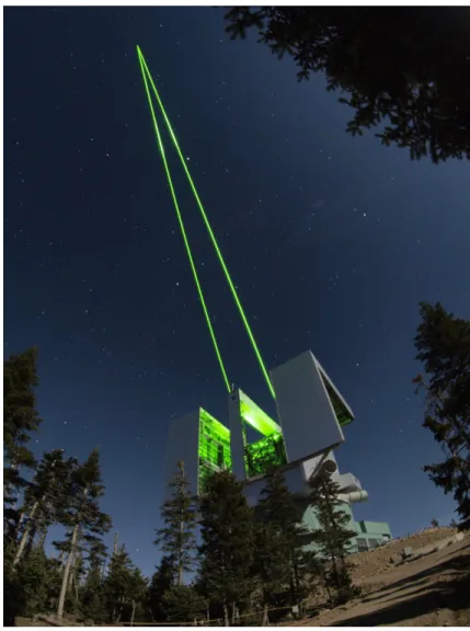
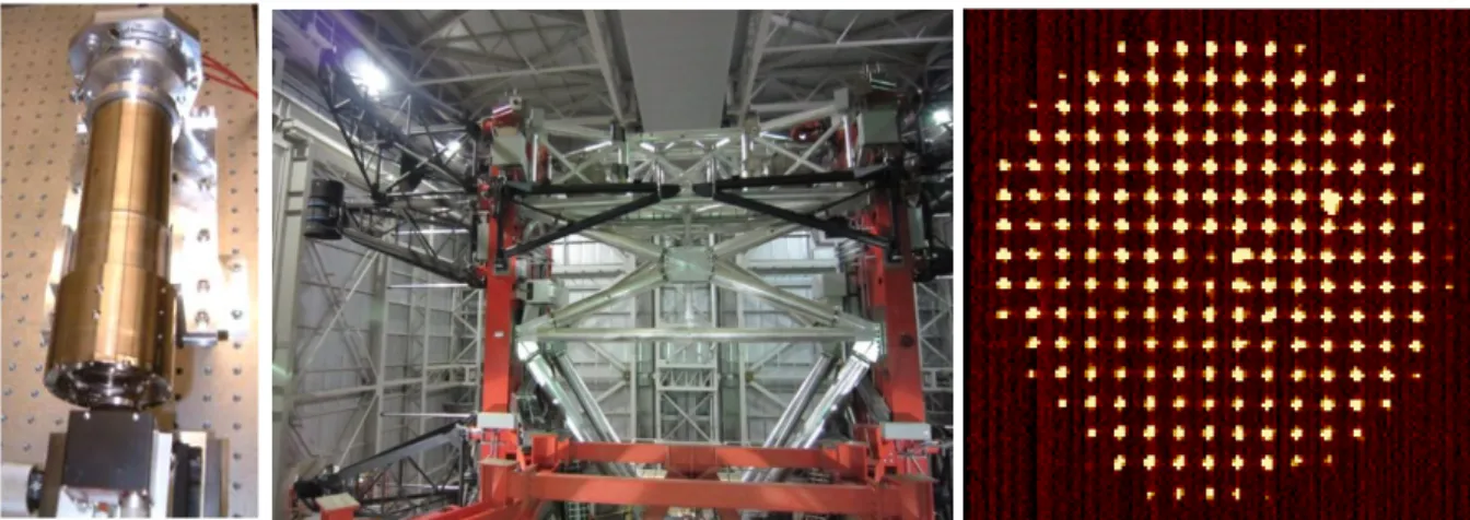
To enable the science programs to benefit from reduced observing times a routine operation under a wide range of observing conditions with low maintenance is a must in that respect. With this goal in mind we have tried to make choices like Rayleigh guide stars based on industrial style laser units to create the guide stars, or fast and easy replacement aids of laser heads. Additionally we have calculated a large margin in the desired photon flux of the LGS, leaving room for atmospheric or instrumental attenuation. Currently we have seen the Rayleigh laser beacons appearing bright on the wavefront sensor. When running the sensors at a 1kHz rate we are still counting up to ~1500 photons per subaperture. Figure 1 shows the ARGOS binocular laser beams when propagated to sky.
In preparation of coming upgrades to the system ARGOS will be capable to include a natural guide star and a sodium line laser in a hybrid AO mode. This will push the system to the diffraction limit at nearly any location on sky with the sodium star, or enable AO observations with very dim natural guide stars.
Figure 1: the large binocular telescope with the ARGOS system propagating a bundle of laser beams on each side of the telescope to sky. Each visible beam consists of three individual laser beams forming the constellation of guide stars in the atmosphere. The pulsed Nd:YAG lasers are triggered at 10kHz, with the wavefront sensors adjusted to receive the scattered light from a 12km distance above the telescope.
`
~
.
i
.`
:.y.
.: a
ir%y'
'r Ì.
' ''114t,,
.
r` 1 : á.
...r k
. ..
I:
1.,.
.;..,..
'i..
.
J.' ..ti.
4i
The direct benefits that ARGOS will bring to the LBT are afforded by the factor of 2-3 improvement in the spatial resolution. Indeed, ARGOS can be considered as a ‘seeing enhancer’ for the existing facility instruments that enables one to address much more of the primary science that has been identified in their respective science cases. This is because:
• observations can be done much faster, saving a significant amount of observing time.
• demanding science programmes, that would normally require the best seeing conditions, can instead be carried out during most nights.
In contrast to single conjugated adaptive optics programs, ARGOS aims to provide enhanced resolution and sensitivity for both imaging and multi-object spectroscopy over a very wide field of view. ARGOS will provide a resolution comparable to that of HST/NICMOS (0.2arcsec in the K-band) over a full 4arcmin field of view. This remarkable performance will greatly boost the capabilities of LUCI, the instrument for which it is primarily conceived. Indeed, it is the increase in speed (to reach a given signal-to-noise) for LUCI’s wide field MOS capability that makes GLAO such a compelling choice for the LBT. The complementarities of this combination to currently operational AO systems will make near infrared observations on the LBT extremely competitive with those attainable at other world-class observatories.
A wide range of science will strongly benefit by the enhanced resolution and en-squared energy that ARGOS delivers. Amongst others the scientific topics that can be addressed with the aid of GLAO span a wide range from extragalactic cases such as high-z galaxy dynamics, AGN and QSO host galaxies, to galactic astrophysical questions about planets, cepheids or stellar clusters. With the GLAO system a major gain in resolution over a wide seeing range can be achieved, thus decreasing integration times required by large factors.
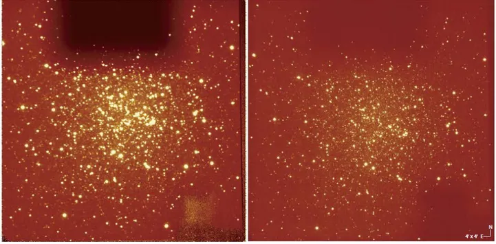
Figure 2: test images with controlling the adaptive secondary mirror on a natural guide star in M13. The commands were routed already through the laser guide star real time controller to the ASM, testing the chain of command that will be used in ARGOS. The image improvement in this snapshots goes from a ~0.9’’ in seeing limited mode (left image) to 0.3’’ resolution with AO control of 150 modes at 400Hz rate. The images have been taken through a 1µm HeI Filter. With angular anisoplanatism being present , the image quality decreases at the borders towards ~0.6’’. With the large corrected field on a single guide star we conclude that this night has been dominated mainly by ground layer turbulence. While still in NGS mode, these images show nicely that the basic functionality of the system is working already.
Launch s stem
Fold mirrors Calibration
swingarms Laser platform
Wavefront sensor
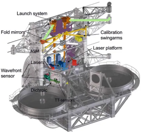
Figure 3: overview of the ARGOS components as installed at the LBT. In the center piece between the two mirrors the laser units are located. Dedicated platforms allow access and servicing those units. From that location on the laser beams are expanded with a refractive beam expander being built into the LBT structure. With large flat mirrors the beams are directed to behind the secondary mirror and sent to sky. When coming back, the photons are split off with a large dichroic mirror, sending the light to the wavefront sensor. Additional swing arms allow moving calibration light sources and optics into the Gregorian prime focus, enabling us to calibrate the adaptive optics during daytime. A total of 8 electronics racks host the required infrastructure of drivers, readout and controllers.
2. SYSTEM DESCRIPTION
ARGOS is based on constellations of laser beacons created by Rayleigh scattering from air molecules with multiple high power pulsed green lasers. Upon a trigger command all laser heads are firing synchronized a ~40ns wide light pulse. Within the laser systems the beams are first expanded to 6mm diameter and then directed to a pupil mirror at the lower end of the launch telescope. With the optics in the laser box the pointing direction and the positioning of the laser beams is performed and as well the required polarization adjustment. Travelling through the launch telescope, the beams are expanded and focused to a 12km distance. After this refractive beam expander two large fold mirrors are placed: one to send the beams cross LBTs primary and one behind the adaptive secondary to launch the lasers to sky. While travelling through atmosphere, some photons out of the pulse will be scattered by air molecules. After 80.06µs photons scattered at a 12km distance arrive back again at the telescope and will be detected by the wavefront sensor.
In front of the instrument rotator structure we separate off the laser photons with a dichroic beam splitter and direct the light towards the ARGOS wavefront sensors. Inside the WFS the beams are first collimated and brought a bit closer to each other. A piezo driven mirror enables a fast correction of the uplink and vibration induced jitter. In the following the Pockels cells gating units slice out exactly those photons being scattered at 12km distance within a 300m range. The light out of this limited volume then falls through the lenslet array onto the detector. The detector itself is a fast large frame PnCCD allowing all three laser guide stars to be imaged on a single frame. With the lasers running at a 10kHz repetition rate, the Pockels cells will be triggered at the same rate. The detector accumulates the photon bunches from ~ten pulses and is read out then.
The frames from the CCD are transferred to the Argos slope computing units. This computer calculates the centroid position of all spots and sends the resulting slope vector to the adaptive secondary mirror where the reconstruction is performed in dedicated fast parallel computers, and the thin shell of the adaptive M2 mirror is set.
Since the laser guide star position as measured on sky does not reflect the atmospheric tilt properly, a separate tip-tilt sensor is required. With calculating the performance of several possibilities, an APD based system was chosen as best performing. The light for this APD quad cell is picked in the rotator structure on the so-called first light adaptive optics (FLAO) board. Additionally some small amount of the natural guide starlight is directed to the pyramid wavefront sensor that is already located on that board. This signal will be used to sense ‘true’ ~10 modes and slowly offset the laser guide star wavefront slopes. The purpose of this truth sensing is to adapt for non-common path aberrations, imperfect calibrations and the slight difference between elongated spots on sky and round calibration spots.
3. LASER & LAUNCH SYSTEMS
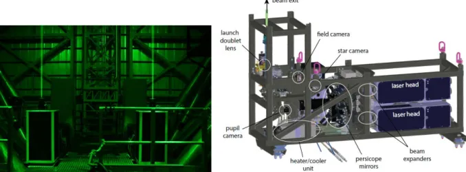
3.1 Laser systemThere are twins of the ARGOS laser system mounted to LBT. Each of the ‘laser boxes’ provides a sealed and temperature controlled environment for the Laser units and the according beam steering and shaping optics. The lasers themselves are pulsed, frequency doubled Nd:YAG lasers produced by Innolas GmbH. Each of the units is specified to emit 18W at a 10kHz rate with ~40ns pulsewidth. The beams are diffraction limited with an M2 better than 1.2. In the beam train after the laser exit, the lasers are expanded to a ~6mm beam and folded by two periscope mirrors into the proper constellation direction. Cameras that monitor the field and the pupil location of the beams are used to control the locations automatically.
Figure 4:left: the two Argos laser systems mounted in the LBT structure. The green laser beams can be seen exiting the boxes before the protective covers have been mounted. Right: CAD model of the laser box without cover.
Inside the laser box the three beams join at a common ‘pupil’ location, where a fast piezo driven tip-tilt mirror is located. This mirror is used to control common position jitter introduced by launch system vibrations. After this mirror the beams are directed to the first launch system input lens. There is another multitude of control and beam diagnostics hardware in the laser system, like power measurement, pulse diagnostics, collimation testing and environment control. Details on the laser system, its mechanics and commissioning can be found in [9][10].
3.2 Launch system
The laser launch system consists of a 40cm aspheric refractive beam expander that widens the laser beams to ~28cm 1/e2 diameter and two large flat fold mirrors to direct the beams across the LBT M1 and behind the secondary to sky. The beam expander is made of a small doublet lens system inside the laser box, sitting on a stage to allow the focus to be changed, and a large fused silica singlet lens with aspheric shape, being located at the top of the telescope. The two large fold flats are produced out of a honeycomb substrate made by Hextek. One of those is mounted directly after the large
120 100 80 80 40 20 o 0 20 40 60 > 1.2E+003 f.1E+003 9.8E+002 8.5E+002 7.2E+002 E002 4.5E+002 3.2E+002 1.9E+002 5.4E+001 _-7.8E+001 [Median FWHM = 2.22" I 50 100 Suboperlure number 150
lens and can be tilted to steer the laser beams position. The other one is placed behind the secondary, passively sending the lasers to sky.
The whole beam path is enclosed to prevent contamination of the system by dust and insects- but as well as a safety and stray light provision prone to the high power of the lasers. Two compressed air driven shutters protect the system when not in use.
3.3 Lasers beacons on sky
The laser and launch system has been installed in a series of campaigns throughout 2012 to 2013 and is now ready for operation at the telescope. Over the process in getting the system to work, we had to learn that the lasers may drop in power over the transport, and required some regular re-tuning of the second harmonic crystals. Now all six heads are close to the desired output power and can be routinely operated with a startup procedure that last less than half an hour. In Figure 5 some images are shown as taken with a separate camera on the LBT mount. The six laser beams can be seen as bright stripes, ending where the atmosphere scatter is getting weak. Within the first nights we had as well some encounter with high cirrus clouds. As can be seen in Figure 5, those appear either as a bit enhanced backscatter, but can stop operation when getting too thick. To quantify the amount of attenuation that the system can tolerate will be one of the tasks for the further commissioning.
Figure 5: The Argos laser constellation as seen with a small auxiliary telescope mounted to the LBT structure. The camera field of view amounts to ~13 arcmin, the constellation diameter is 4 arcmin. To the left the Rayleigh scattered light from the beams can be seen, while in the middle picture some high layer cirrus clouds enhance the scatter in ~10km height. To the right a strong cloud layer starts to fully attenuate the lasers.
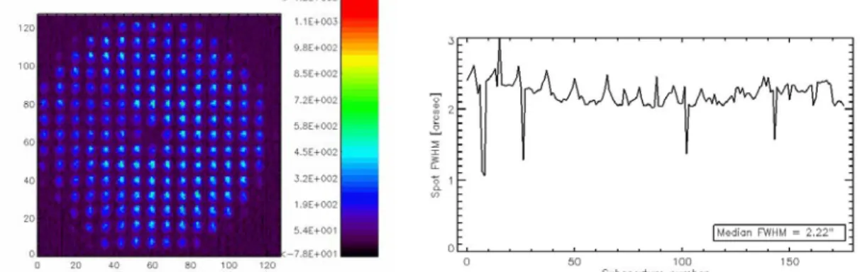
On the laser spot size on the wavefront sensor, unfortunately we found a similar problem as many LGS systems have been facing at start. Apparently the the spots on sky showed some elongated shape, changing with the focus of the launch telescope. As well the spots on the WFS where never smaller than ~2.5 arcsec, as shown in Figure 6. To verify this we have placed a camera in the focus of the launch telescope, moving it through the focus on a star. The clear astigmatic shape found there is consistent with one or two of the Hextek fold flats being deformed spherically by up to 2 microns p-v. Currently we are preparing a more accurate measurement device and a corrective optics to compensate for the aberration.
Figure 6: LGS spot size on the WFS. To the left one of the three laser guide stars is seen on the sensor. The individual spots are all above 2’’ in diameter, while should have been half of that. Aberrations in the launch system are causing enlarged spots.
lenslet Collimator
array by driver
PnCCD dark wheel field stabilization
Pockels cells pupil stabilization
motors
internal calibration units atrol cameras
window
4. WAVEFRONT SENSING & CONTROL
The Argos wavefront sensor is based on a Shack Hartmann (SH) scheme to detect the laser guide stars. In the plane of the 12km distance focus, a field stop with ~4.5arcsec diameter is the entrance to the optics chain building up the sensor. For each of the guide stars, a first collimation lens re-images the pupil over a periscope onto the entrance of the Pockels cells. The periscope mirrors on one hand just brings the constellation closer together, on the other hand a PZT driven mirror is included, that is used to stabilize the SH spots on the sensor.
In the collimated beam –being strictly collimated only when the laser pulse is exactly at 12km distance- a Pockels Cell assembly is located. This unit acts as an optical shutter, opening 80µs after the laser pulse has been send to sky and closing again 2µs later. This lets only those photons pass towards the CCD that have been scattered between 12 and 12.3 km above the telescope. With the lasers repetition rate being set to 10kHz, we accumulate the charge of ten pulses on the sensor before we the readout is triggered.
After the gating units each beam passes a focusing lens and a common collimator that form a pupil image on a single lenslet array directly before the CCD. The optics is adjusted such that the three SH patterns a nicely distributed over the CCD, each sub-aperture owns 8x8 pixels and the split frame transfer does not cross sub-apertures. More information on the wavefront sensor performance is given in [8].
The CCD itself is based on a deep- depletion technology, offers 264x264 pixels and a low readout noise at a kHz frame rate. Details can be found in [6].
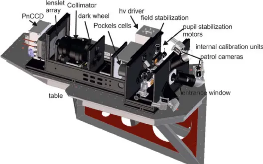
Figure 7: drawing of the ARGOS wavefront sensor. The light from the three LGS is coming from the right side and enters the sensor through a field stop. Patrol cameras with an 1 arcmin field of view aid the acquisition of the LGS. A first collimator and periscope is actively used in closed loop to control the field and pupil position on the CCD. The three pockels cells gate the desired light column out of the backscattered signal. The collimator sends the light onto a common lenslet array and finally onto the CCD where the Shack Hartmann pattern is seen.
Commissioning and installation of the first ARGOS wavefront sensor unit and the according optics and electronics started in February 2014 and continued in several runs until first light on sky in May: The main components are a dichroic beam splitter and fold optics in the telescope optical train, the wavefront sensor units themselves and the calibration source.
Details of the calibration source are laid out in chapter 6. Those units mimic the LGS with light passing the adaptive secondary mirror for the interaction matrices to be recorded. With the limitations the source and gating units still had at that run, primarily one Shack Hartmann pattern has been used at a time.
The sensors Interaction Matrices were recorded at 300Hz following a push-pull approach using a set of 150 orthonormal Karhunen-Loeve modes. Each sensor was then calibrated as a SCAO system using a SVD.
C= R L o PYR 2 G S LGSW 0 W 149 P V R 1000 1-N E c ioo 10 io Mode Number 100
In a closed loop test of the sensors without time-varying disturbance the communication between the FLAO pyramid WFS and ARGOS was tested successfully: While waiting for the APD installation, scheduled for next summer, the tip-tilt signals have been measured by the pyramid wavefront sensor of FLAO using the ARGOS on-axis calibration source. Pyramid slopes (sPYR) were routed to the ARGOS slope computer, concatenated to slopes measured by the SH sensor
(sLGSW) and then sent to the ASM where a block reconstructor (R) of following form was uploaded:
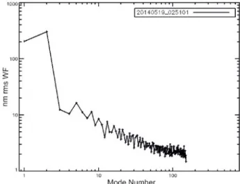
In Figure 8 the standard deviation of the residual SH slopes projected on the modal basis are plotted. A strong tip-tilt component can be seen and is expected to reflect purely the system vibrations. Excluding this tip tilt component, the residual WF error estimated by the 150 modes amounts to 46nm rms.
Figure 8: plot of the modal variance of the SH slopes residual from the closed loop test of one SH sensor with the ASM. No disturbance was uploaded on the mirror, the SH sensor was measuring at 1kHz for 150 modes while the image stabilization was implemented by the Pyramid WFS.
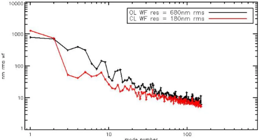
Within this commissioning run we were able to test the system on sky: Despite all the 3 LGS were properly acquired and the laser light was seen on all the 3 sensors as shown in Figure 9, just a single could be tested at that time in closed loop with the ASM correcting effectively 60 modes at 1kHz rate. The pyramid WFS was used to measure the atmospheric tip-tilt, pointing on a mag 13 star with measuring at 400Hz in bin 2 condition. A preliminary result of this first closed loop on the ARGOS LGS is shown in Figure 10. The standard deviation of the WF evaluated projecting the SH slopes on the 150 modes: in open loop amounts to 680nm rms, while the residuals of the AO correction is down to 180nm rms.
10000 1000 m E 100 E c 10 1 OL WF res = 68Onm rms CL WF res = 18Onm rms 1 10 mode number 100
Figure 9: first laser light on the laser guide star wavefront sensor. All three Shack Hartmann patterns created with the range gated laser guide stars appear on the detector. With the received flux we have seen from a 12km distance of 1500 photons we are close to the theoretically calculated value of 1800 photons per integration and sub-aperture. With this margin in place we can accept some cloud attenuation, or shorten the range gate if desired.
Figure 10: modal variance of the slopes measured at 1kHz on-sky by one SH sensor. The black line shows the open loop measurements while the red one shows the AO closed loop residuals. The WF error reconstructed on the 150 modes (tip-tilt excluded) amounts to 680 and 180nm rms respectively.
5. THE NATURAL GUIDE STAR TIP-TILT CONTROL
Since the overall tilt signal cannot be measured from the LGS, we are implementing a separate NGS tip-tilt tracker. To detect the natural stars light, the entrance windows of the LUCI instruments reflect the visible part of the spectrum towards a board, containing the ‘first light adaptive optics’[4]. On this FLAO board two capabilities are installed: the NGS pyramid sensor and a lenslet quad cell feeding light via fibres to an APD detector. The pyramid sensor from the FLAO will be used in laser guide star mode as truth sensor, updating the slope offsets of the LGS detector at slow rates, but as well can be used as a tilt sensor.
The natural guide star tip-tilt system is a quad-cell system using a four-channel Excelitas SPCM-AQ4C Avalanche Photo Diode (APD) module as the detector. The detector is housed in a temperature controlled electronics rack on the telescope instrument platform. The light is collected in the focal plane by a 2 by 2 lenslet array. Behind the lenslet array a precision mask plate holding four 150micron fibers at the exact location of the four pupil images has been glued to the lenslet array. The fibers guide the light for 25m from the lenslet array out of the guiding unit over the cable wrap to the detector array. The lenslet array is located on the existing wavefront sensor board of the Acquisition, Guiding and Wavefront sensing (AGW) units of the telescope and can thus be moved around in a patrol field of roughly 2 by 3 arcmin. This configuration has the distinct advantage that we do not need much space inside the already very full AGW units and the
53 aa QQ ioa rat 123 114 raz 33 44 QQ 81 roa rar 123 r]d raz
711L
detectors and electronics can be placed in a controlled environment. The lenslet array has been designed to allow for a field of view of 2.2 by 2.2arcsec in the sky but to maintain good response also under very good seeing conditions. To achieve this, the lenslets have their peak slightly offset towards the quad cell center. The lenslet arrays have been manufactured to our specifications by Carl Zeiss, Jena. Laboratory measurements show that we achieve a photon detection efficiency of approximately 50% from the level of the photon entry of the lenslet array including the losses in fiber couplings in good agreement with the design goal. Simulations suggest that we can achieve a tip-tilt guiding jitter of less than 100 milli-arcsec for an 18mag star. In the laboratory we have performed raster scans of the lenslet array using different size light spots to quantify the response under different seeing conditions to verify that the unit will also show good performance under excellent seeing conditions. In one case we used a spot size corresponding to 0.9arcsec in sky and steps of 0.14arcsec. The sensitivity across the array after correcting for dark current and flat-fielding between the channels is shown in the left most image in Figure 12.Similarly we have made a raster using a spot size of 0.23arcsec as shown in the right most image in Figure 12. From these images it can be seen that the sensitivity is very smooth across the array and even under the unrealistically good seeing of 0.23arcsec (we are operating in the optical) the sensitivity is only reduced by about 25% and for the more normal case of 0.9arcsec there is no significant reduction in the sensitivity.
Figure 11: left: test setup in the laboratory of the TT fibre head. Right: the quad cell lenslet array in its mount.
Figure 12: The signal as a function of (x,y) position for two different spot sizes. In the left most image a spot size corresponding to 0.9arcsec on the sky has been used and in the right most image a spot size of 0.23arcsec. The outer four images represent the response of the individual channels while the center image is the sum of the four outer images and thus representing the overall sensitivity of the array. The channels have been dark subtracted and flat fielded. The intensity scale ranges from 0:05 to 1.0 for all the images.
T
!'aa
s 7-7...
* * * + # * * * * * 4 4 # ## *
* *
* # to w#+#
t# 4; 4
i
; t t
t t* 4
*
t Y*
++t+tti
#04*+4.t
t
1* 4 f
4t 4
i*
i # #
#* T *
t IF41.01i0414
t# t**
4 44 4 4
.#ti#4
4 0 { t*4
* *i 4 4 i t
+ 4 1 46. CALIBRATION SOURCE
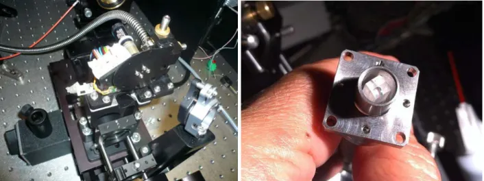
One of the crucial parts of an AO system is the calibration of the deformable mirror to the wavefront sensor. Such calibration can be a time consuming task, which is best performed during daytime to avoid loss of the precious night time. The currently used NGS AO calibration system at LBT needs installation of opto-mechanics, taking about half an hour. In order to accelerate the process we have installed a swing arm, being deployable within minutes. The calibration source itself consist of an optical assembly, including a hologram to simulate our three laser guide stars as appearing in the prime focus of the Gregorian telescope. Green diode light sources are feeding the optics for the LGS calibration and a white light source for on-axis alignment and non-common path measurements is included.
Figure 13:left:the barrel containing the calibration optics. Middle: the long swing arms are made from carbon fibre and can move the optics to the prime focus of the telescope. To the right the spot pattern on the SH sensor is shown. Two extended ‘blobs’ can be seen where the strongly defocussed higher orders of the hologram contaminates some sub-apertures.
We successfully aligned the calibration source in May 2014 for the DX [right] wavefront sensor and could use it for the first calibrations. However, we found following issues that still need to be addressed:
• The higher orders of the hologram produce strong ghosting.
• Some plate scale mismatch between source and sensor needs to be solved.
For the first problem we expect that a new hologram can solve for. Currently, the light distribution between main order and higher order are 60/40- built with the assumption in mind that the highly defocussed high orders are blocked at the field stop. In reality several sub-apertures can see quite some high illumination, disturbing an accurate spot position determination. It is currently under investigation if a new hologram with a split of 94/6 between main order and higher orders can mitigate the problem. The cause of the plate scale mismatch is not yet fully understood, However, will be mitigated with making the entrance windows adjustable and re-scaling the fiber plate.
7. SYSTEM CONTROL ARCHITECTURE
The ARGOS control architecture consists of 7 different loops and procedures, which partially have to communicate to already existing parts on the telescope. Therefore, we had to redefine some interfaces or even refactor existing software. In addition to the control loop software there are of course a huge amount of devices to control, set, supervise and monitor. Details on the software development can be found in [11].The loops are the following:
• The high order laser guide star control loop running on 1kHz by examining the wavefront sensor (LGSW) image and applying the correction the adaptive secondary (ASM)
• The jitter stabilization loop, which is also examining the wavfront sensor data and takes the tip tilt of the lasers to individually stabilize the spot positions on the sensor with a PZT driven tip tilt mirror on a 1kHz base. • The pupil stabilization loop, uses the wavefront sensor data to move lenses in the wavefront sensor to stabilize
the pupil on the wavefront sensor image. The loop is based on a huge transform to determine the parameters of the spot pattern at a whole.
iploisountionsmeasinalisumaimeni
Ikllz asynchronousIkllz
Ikliz VibCtrl
offload
«11Iz.
Pup Diag Field Diag
Ikllz Clock <I liz 101Iz
«I II/
TCS IIKUUI,IiI,I TRUSas nchronous <I I-iz
• The natural guide star tip tilt control based on the APD signals stabilizes the image with tilting the shell. The offload to the ASM hexapod and the telescope finally guides the telescope.
• The LGS focus control procedure, which is not a permanently running loop but an action on demand to evaluate the spotsize on the wavefront sensor by moving the telescope lenses of the laser launch system and calculates the optimal focus position from the wavefront sensor data.
• The laser system flexure control loop, which monitors the pupil position and the field position of the laser system. It is based on two cameras imaging the field and the pupil locations of the three laser beams. The control of the positions utilizes a pair of mirrors in a periscope setup that are set together.
• The LGS field position offload based on the LGS light being reflected by the field stop at the WFS entrance and can be seen on the patrol cameras. The position evaluation in a quad cell mode enables the position to be determined even when the LGS vanishes in the hole of the stop.
• The laser stabilization feed forward loop or vibration compensation loop. Accelerometers behind the large launch optics do measure the vibrations and a mirror in the laser boxes compensates in a feed forward loop these vibrations in common for all three lasers per side.
• The truth sensing loop does permanently upgrade the slope offsets between the laser guide star wavefront sensor and the existing pyramid sensor to compensate for mis-collimation and changing non-common path aberrations.
Figure 14: sketch of the various loops being active in the system and the respective actions between the components. On the launch side most loops are in the ~1Hz Range to slowly compensate for flexure and offloads. The vibration compensation can run up to a kHz rate, but as well with a high sensitivity at low frequencies. On the receiving path the ASM runs at a 1khz rate being bound to the readout speed of the LGSW CCD. A very slow ‘truth’ sensing update of the slope offsets keeps non-common path errors under control.
8. OPERATIONAL ASPECTS
Operating high power lasers on sky requires several pre cautions for safety and as well in administrative aspects. Since LBT is located in the US, as well special arrangements are required. Details are given in [5], so we just give a summary table here:
• Airplane spotters are required by FAA regulations. This imposes the need at LBT to bring ~4 people every laser night up to the mountain, equip them with proper clothing, communication and provide training to them. With two of the people standing outside at a time, the shifts need to be organized accordingly. LBT currently is planning for a Tbad system that pings the radio transponders of planes, which finally may result in spotter operation being obsolete.
• A satellite avoidance system needs to be in place. This implies that observations have to be planned in advance and a target list has to be sent to space command, that returns with a blackout list for given times.
• Coordination is done as well with the nearby airbase and the other optical telescope on the site.
• Internally operation and safety aspects are mostly handled by the laser interlock system taking care of warning lights, alarms, closed covers etc. Additionally a personal check of the dome is done by the operator, finally enabling the laser propagation and alerting the observatory staff that lasers are operated.
9. SUMMARY
ARGOS has seen first light with the laser guide stars on sky. A double constellation with Rayleigh guide stars has been successfully projected. With the first detection of the LGS on one of the LBT sides and a first loop closure on a single star, a major milestone has been passed. In the following year we do expect the remaining technical issues to be solved and the commissioning to be finished with success.
REFERENCES
[1] Hofmann R. et al., „The cryogenic MOS unit for LUCIFER“, Proc. SPIE 5492, pp. 1243-1253 (2004) [2] Buschkamp P. et al., “LUCI2: binocular and LGS/NGS AO modes of LUCI at the LBT” SPIE 9147-58, (2014) [3] Quirós-Pacheco F. et al., “First light AO (FLAO) system for LBT: system characterization and performance
optimization“, SPIE 7736-128, (2010)
[4] Esposito S. et al., “Natural guide star adaptive optics systems at LBT: FLAO commissioning and science operations status”, SPIE 8447, (2012)
[5] Rahmer G. et al., “Early laser operations at the Large Binocular Telescope Observatory” SPIE 9149-86, (2014) [6] Orban de Xivry G.,“ARGOS wavefront sensing: from detection to correction” SPIE 9148-112, (2014)
[7] Busoni L. et al.,” Laser tomography with the ARGOS Sodium upgrade: towards visible AO correction” SPIE 9148-139, (2014)
[8] Bonaglia M. et al., “Pre-shipment test of the ARGOS LGS wavefront sensor” SPIE 9148-212, (2014) [9] Deysenroth M. et al., “ARGOS Laser system mechanical design” SPIE 9148-128, (2014)
[10] Raab W. et al., “The ARGOS laser system: green light for ground layer adaptive optics at the LBT SPIE 9148-131, (2014)
[11] Kulas M.et al., “Practical experience with test-driven development during commissioning of the multi-star AO system ARGOS” SPIE 9152-11, (2014)