HAL Id: hal-00770439
https://hal.archives-ouvertes.fr/hal-00770439
Submitted on 6 Jan 2013
HAL is a multi-disciplinary open access
archive for the deposit and dissemination of
sci-entific research documents, whether they are
pub-lished or not. The documents may come from
teaching and research institutions in France or
abroad, or from public or private research centers.
L’archive ouverte pluridisciplinaire HAL, est
destinée au dépôt et à la diffusion de documents
scientifiques de niveau recherche, publiés ou non,
émanant des établissements d’enseignement et de
recherche français ou étrangers, des laboratoires
publics ou privés.
Dynamic motion imitation of two articulated systems
using nonlinear time scaling of joint trajectories
Karthick Munirathinam, Sophie Sakka, Christine Chevallereau
To cite this version:
Karthick Munirathinam, Sophie Sakka, Christine Chevallereau. Dynamic motion imitation of two
ar-ticulated systems using nonlinear time scaling of joint trajectories. 2012 IEEE/RSJ International
Con-ference on Intelligent Robots and Systems (IROS), Oct 2012, Vilamoura-Algarve, Portugal. pp.3700
– 3705, �10.1109/IROS.2012.6385681�. �hal-00770439�
Dynamic motion imitation of two articulated systems using nonlinear
time scaling of joint trajectories
Karthick Munirathinam, Sophie Sakka, Christine Chevallereau
Abstract— This paper proposes the analysis of two strategies for motion imitation of articulated systems with balance con-straint. The two systems have different dynamic characteristics and their respective motions are restricted to the sagittal plane. The first strategy is based on nonlinear time scaling of joint trajectories ensuring that the balance of the imitating system is maintained through the motion. With this approach, the imitating system tracks the input reference trajectory without modifying the task to be accomplished by compromising on acceleration of the motion to ensure the condition for the balance is satisfied. As a consequence of reducing acceleration, there exists a delay between the reference system and the imitating system. However, we have ascertained that the joint angles are accelerated for the delay created to catch up with the reference motion. In contrary, the second strategy modifies directly the joint angle trajectories to ensure balance. This approach is the traditional approach in motion imitation used in human to humanoid motion transposition. We have formulated both strategies as an optimization problem in order to obtain feasible joint trajectories for the imitator. This work is a preliminary study for the imitation of a human being by a humanoid robot.
I. INTRODUCTION
In the near future, the humanoid robots will inherit the capability to observe and imitate like human beings. The mo-tion imitamo-tion plays a key role for robot social learning [1], [2]. The motion imitation is a mechanism for programming robots actions and a tool for the communication between the human being and the robot. It is also an easy way to generate feasible joint trajectories to achieve a particular task in higher dimensional spaces of a robot. This enables the humanoid robot to work in an environment along with human beings autonomously with maximum throughput.
Many research works have been undergone in order to fuse the human-like motion dynamics and control to humanoid robots. In order to achieve this objective the humanoid robot should capability to imitate the human motion. In fact, this objective is the basis for the humanoid robots to perform complex movements. Although the motion imitation is just mapping the human motion on to humanoid robot which has similar appearance might be simple at the first glance; but the complexity involved between the conversion processes is very tedious and it is a herculean task to achieve good imitation. This is because of the kinematic and the This work was supported by IRCCyN Robotics Lab and WILLPOWER scholarship
Karthick Munirathinam,Sophie Sakka and Christine Chevallereau is with IRCCyN,Robotics Team, Ecole centrale nantes, 44321 Nantes, France
karthick.munirathinam@irccryn.ec-nantes.fr sophie.sakka@irccryn.ec-nantes.fr
christine.chevallereau@irccryn.ec-nantes.fr
dynamic diverseness that exists between the human being and the humanoid robot. The main difficulty to overcome in developing human motion for humanoids are the anthropo-morphic differences between the human and the humanoid, the physical limits of the robots actuators, the balance of the robot [3] and the collision avoidance.
There are many approaches to map the human motion to humanoid motion. The velocity filtering based motion imitation [4] was the basis for upper body motion imitation which was later adopted by [5] and [6] for whole body mo-tion imitamo-tion ensuring the Zero Moment Point (ZMP) is re-stricted at the center of the support polygon for all the motion primitives obtained from human motion capture data. Several optimization based approaches have also been proposed for motion imitation [7],[8],[9],[10]. But, these approaches are restricted to the upper body motion. Whereas [7] adapted the preview control proposed by [11] for the lower part of the humanoid robot. Again, this approach also ensures the ZMP is at the center of the support polygon and modify the pelvis motion based on linear inverted pendulum approach. [12] and [13] optimized the norm of the human ZMP trajectory and the desired humanoid ZMP trajectory in order to compute the joint angles for the humanoid robot. This ensured the balance of the humanoid robot within safety limits. [14] proposed that the humanoid balance is achieved by minimizing the angular momentum at the center of mass.
The imitation methods mentioned above are solely based on modifying the joint variables. The joint trajectories are modified directly but the time reference remains the same between the two systems . The method we proposed is deal-ing with motion imitation by time scaldeal-ing, where the joint trajectories are scaled with respect to time. The trajectories tracked by the reference and the imitator systems are similar. The concept of time scaling of manipulator trajectories was introduced by Hollerbach in 1983 [15]. The trajectory of a planar manipulator is scaled with respect to time with a constant scaling factor obeying the actuator limits of the robot. In the area of humanoid robotics, Chevallereau has implemented the time scaling control of the under actuated biped robot RABBIT [16]. Here the trajectory of the biped is time scaled to obtain a convergence of biped walking motion toward stable cyclic motion. The joint trajectories were parametrized by a virtual time and the second derivative of the virtual time is considered as a supplementary control input. Similarly, Djoudi extended the concept for biped robots with feet which intern resulted in faster convergence toward cyclic motion [17].
optimization approach for motion imitation. We validate our approach using a simple simulation in the sagittal plane consisting of two open kinematic chains of n bodies linked to a foot in surface contact with the ground. The two systems have similar kinematics but different inertia characteristics. One chain performs the reference motion, the second one will have to imitate the motion while also keeping its balance. The torques and forces exerted by the links due to motion is reflected by means of ZMP trajectory. The main objective of our work is to establish an effective approach which includes kinematic and dynamic properties to improve the quality of motion conversion while ensuring the balance or equilibrium of the humanoid during the motion transposition. Our approach emphasizes on the fact that the ZMP is not restricted at the center of the support polygon, but it can be placed anywhere in the support polygon to ensure the foot ground stability of the system. The joint angles, joint velocities and torques limits are taken as constraints along with ZMP during motion imitation. In the second strategy, we have taken the same model and optimized for joint angle trajectories of the imitator. The constraints equations will remains same as the first approach.
The rest of the paper is structured as follows. In section II a brief overview of model formulation is given. In section III, the imitation problem is formulated as an optimization problem under inequality constraints for both time scaling and joint angles approaches, followed by its results in section VI. In section V, we discuss the pros and cons of both approaches and conclude the paper in section VI .
II. MODELFORMULATION
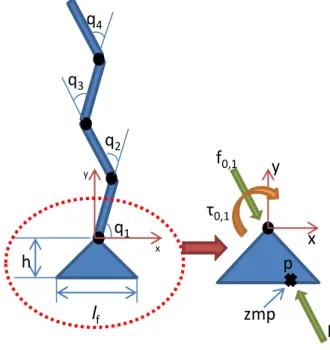
Let us consider an open kinematic chain of n rigid bodies with a massless rigid foot at its lower extremity as illustrated in Fig. (1). The foot is in surface contact with the ground, and the system keeps its balance during the whole motion. We introduce a second open kinematic chain with similar kinematics as the first one, but different geometric and inertia characteristics. Our objective is to reproduce the motion of the first model, called performer, by the second model, called imitator, under the constraint that the imitator should keep its balance during the motion. Our study focuses on the simpler case of motions in two dimensions to understand the effects of motion transposition when the balance is at stake. We assume that there is no external contact other than the foot ground contact. The dynamic model can be written using the Recursive Newton-Euler formulation isolating successively the n bodies of the kinematic chain. Isolating the i-th body (i= 1, n), we obtain the Newton (1) and Euler (2) equations.
fi−1,i− fi,i+1+ mig− mi˙vci= 0 (1) where mi is the mass of body i, vci is the linear velocity vector of the center of mass ciof link i, fi−1,iand fi,i+1denote the coupling external forces applied to body i by bodies i− 1 and i+ 1, respectively. g is the acceleration vector due to
h
q
1q
2q
3q
4 y xzmp
0,1f
0,1R
y
x
l
fp
Fig. 1. Foot connected with n-serial links. Here n= 4
gravity.
τi−1,i= τi,i+1+ (ri−1,i− ri,ci) × fi−1,i− (−ri,ci) × (fi,i+1) + Iiω˙i+ ωi× (Iiωi)
(2)
where Iiis the inertia tensor of body i at ci, ωiis the absolute angular velocity vector of body i, τi−1,i and τi,i+1 are the external torques vectors applied to body i by bodies i− 1 and i+ 1, respectively. ri,ci and ri−1,i are the distance vectors from the origin of link i to ci and from the origin of link i− 1 to the origin of link i, respectively.
The equilibrium law at the isolated foot (body 0) allows to extract the position of the ZMP on the ground:
f0,1= R; (3) τ0,1+ f0,1× zmp = 0 (4) zmpx= (τ0,1− h ∗ f0,1x )/ f0,1y (5) where τ0,1 is the ankle support foot torque vector, R is the ground reaction force vector, h is the ankle height. zmp is the absolute position of the the zero moment point.
III. OPTIMIZATIONPROBLEMSFORMULATION We first establish a generalized framework of the two optimization problems and will next specify the objective functions and constraint equations depending on the chosen strategy. The joint angle trajectories of the performer are noted q and are directly measured from its motion. The joint trajectories of the imitator are noted q∗ and their n com-ponents q∗i (i= 1, n) are represented as n cubic parametric functions of time.
with j= 1, N. tj∈ [t0,tN] is the reference time, N being the total number of time steps.[bi
0bi1bi2 bi3] are the coefficients of the polynomial.
Let ℓf be the length of the foot (horizontal axis). We restrict the upper bound ℓp and the lower bound ℓn of the imitator’s support polygon with some tolerance index to ensure the ZMP never reaches the boundary of the support polygon.
ℓn= −0.9 ∗ ℓf/2 and ℓp= 0.9 ∗ ℓf/2 (7) The general optimization problem is formulated as,
min
x F(x) (8)
subjected to the inequality constraints (∀tj∈ [t0,tN])
no take-off → Ryj> 0 (9) no slipping → µ Ryj≥| Rxj| (10) ZMP → ℓn≤ zmpxj≤ ℓp (11) Technological constraints (∀tj∈ [t0,tN], i = 1, n): | ˙qi| ≤ q˙maxi (12) | τi| ≤ τimax (13) Where,
Rj= [Rxj, Ryj] is ground reaction force at instant tj µ is the coefficient of friction
˙
qmaxi is the maximum joint velocity of link i τimax is the maximum joint torque of link i
A. Joint angle trajectories optimization
This approach is the traditional approach used so far in the domain of motion imitation. We add to classical joint trajectory optimization the constraint (11) on the ZMP of the imitatorto ensure the balance during the performance of the motion. The parameters to optimize are the 4× n coefficients of the parametric equations (6).
The objective function F is based on the minimization of the joint trajectories using a quadratic criterion:
F(q∗) = N
∑
j=1
(q(tj) − q∗(tj))2 (14)
under the inequality constraints (9) to (13). The system also must respect the joint angle limits of the imitator:
qmini ≤ qi≤ qmaxi i= 1, n (15) where qmax
i and qmini are the joint angle upper and lower limit respectively of link i.
The above joint angle trajectories optimization formulation ensures that the joint angles of the imitator and the performer remain as close as possible at each time step while satisfying the constraint equations.
B. Time scaled optimization
In this approach, the time is scaled in order to influence the ZMP position by accelerating or decelerating the motion of the system. The motion is locally decelerated to ensure the constraints are satisfied mainly when the balance of the imitator is threatened. In order to catch up with the performer’s motion, the joint trajectories are then accelerated and put back in synchronization. The time scaling is done globally, which implies all the joint trajectories are scaled by the same scaling factor to ensure proper imitation in terms of motion coordination. The performer executes its motion in the reference time t, whereas the imitator executes its motion in the virtual time t∗which is obtained from the optimization process. The virtual time is expressed as a cubic function of the reference time and the coefficients of the polynomial are optimized for the entire motion to be imitated, from t0to tN.
t∗j = a1tj+ a2tj2+ a3tj3 (16) Where[a1 a2 a3] are the 3 parameters to be optimized.
In the ideal case, if the imitator have similar dynamic characteristics than the performer, then the virtual time will be identical to the reference time. However, this will not be the case if the dynamic parameters of the two systems are different. Moreover, in case of complex motions, we may need to divide the total simulation time into p intervals and use splines on each intervals for the time scale optimization. In our case, the motion was chosen to be reproduced by one polynomial for simplicity motives.
In this approach, the objective function F relies on the time: F(t∗) = N
∑
j=1 (tj− t∗j)2 (17)under the inequality constraints (9) to (13). Here we must also insure as a constraint that the virtual time is never greater than the reference time so that the imitator’s motion is never ahead of the performer’s motion.
t∗j ≤ tj ∀ j ∈ [0, N] (18) The constraint (15) on the joint angle limits cannot be applied in the time scaling approach because the joint angles can only be restricted by modifying the joint trajectories directly. To solve this, the values of the joint angles are saturated to the limits of the imitator when reaching it. Using this formulation, the virtual time is optimized to be as close as possible to reference time while respecting the balance of the system and other specified constraints.
The virtual time is applied to Eq. (6) with the coefficients bik (k= 1, 4, i = 1, n) remaining constant. For the time scaling, the polynomial joint trajectories were obtained by interpolation of the reference trajectories.
IV. RESULTS
We apply the two optimization methods on 4-bodies open kinematic chains which characteristics are summarized in Tab. I. When considering motion imitation of systems stand-ing on a foot, the management of balance by the imitator is made much easier when choosing a bigger foot than the performer. This is often the case of humanoid robots whose feet are bigger than human beings’ compared to their respective heights. In our simulation, we have chosen a smaller foot for the imitator to point out the performance of our algorithm in terms of balance management. The length of the performer’s foot represents 22% of its total height (when q= 0), while the imitator’s foot represents 15% of its total height. A direct consequence of this difference is that if the motion of the performer drives its ZMP close to the boundary of its support polygon, it is not possible for the imitator to replicate the motion and keep its balance as explained in the following application example.
TABLE I DYNAMIC PARAMETERS system Parameters performer link1:mass=2kg,length=20cm link2:mass=2kg,length=20cm link3:mass=2kg,length=20cm link4:mass=2kg,length=20cm foot: fl=20,h=10cm imitator link1:mass=4kg,length=40cm link2:mass=4kg,length=40cm link3:mass=4kg,length=40cm link4:mass=4kg,length=40cm foot: fl=26cm,h=14cm
By definition, the motion of the performer always leads to a ZMP trajectory within its support polygon. Indeed this reference system is defined to keep its balance during its motion. Figure (2) compares the ZMP trajectory obtained by the performer during a motion to be imitated to the imitator’s ZMP trajectory of its converted motion in three situations: without optimization, with time scaled optimization and with joint trajectories optimization. In the first case, a direct mapping of the joint trajectories from the performer to the imitator was realized. As expected, direct mapping does not allow to keep the balance of the imitator. This can be observed as the ZMP trajectory goes out of the support polygon represented by the two horizontal lines in Fig. (2). The ZMP trajectory remains inside the support polygon for the complete motion if the balance constraints are applied for both optimization strategies. We can observe in Fig. (2) that both optimization strategies propose the closest solution to direct mapping that meet the constraints requirements. As a consequence, if the direct mapping leads to a ZMP trajectory outside the imitator’s support polygon, the optimized solu-tion will propose the first tangent ZMP trajectory inside the support polygon. This case may be dangerous. This justifies the use of a tolerance interval defined in Eq. (7) on the support polygon to ensure the ZMP never reach its edges.
By this, we can modify the motion of the imitator within the safe region of the support polygon.
Time scaling optimization affects the temporal evolution of the joint trajectories without changing their values (except when the joint limits of the imitator are reached), and joint trajectories optimization is based on geometric evolution by modifying the joint trajectories directly to satisfy the constraint equations. The ZMP trajectory is the function of joint forces and joint torques, which are the consequences of joint angles, joint velocities and joint accelerations. In the time scaled approach, the virtual time is expressed as a cubic polynomial of reference time. By modifying the coefficients of the polynomial of virtual time, we can modify the joint angles, velocities and accelerations of the links. This intern modifies the ZMP trajectory to ensure the balance of the system. Whereas in the joint based approach the joint angles, velocities and accelerations are modified directly to satisfy balance criteria. 0 0.5 1 1.5 2 2.5 3 3.5 -1.5 -1 -0.5 0 0.5 1 1.5 2 time (sec) zm p ( 1 0 x cm s) performer
imitator with timescale opt imitator without optimization imitator with joint based opt
Fig. 2. ZMP trajectories with time. The upper and lower limits of the support polygon of the imitator are[ℓn, ℓp] = [−11.7, 11.7] cm represented by the two horizontal lines. The boundaries of the support polygon of the performerare[−10, 10] cm.
The plot (3) shows the matching virtual time versus the reference time. The linear blue curve represents the real or reference time. The red one represents the scaled time, and must always be under the reference time curve to meet optimization constraint 18. Considering the scaled time, we can point out three cases:
Case 1: Slope of the curve< 1
The imitator cannot execute the motion because the constraints are not satisfied. The imitator tends to slow down the motion in this region of the curve.
Case 2: Slope of the curve = 1
The imitator can execute the motion at the same rate with or without the time delay with respect to the performer. When t = t∗ then the performer and imitator will be in perfect synchronization.
The imitator accelerates its motion to catch up with the performer’s motion. In this region the imitator executes the motion faster than the performer and at the same time the constraints are satisfied.
If we correlate this plot with the ZMP plot (2), we can observe that the virtual time lags behind the reference time when there ZMP is close to the boundary of support polygon and when ZMP is away from boundary of support polygon the motion tends to speeds up to reduce the error between the two curves.
0 0.5 1 1.5 2 2.5 3 3.5 0 0.5 1 1.5 2 2.5 3 3.5
Reference time (sec)
V ir tu a l ti m e ( se c) Reference time scaling
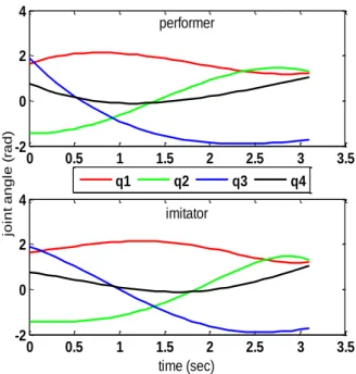
Fig. 3. Virtual time versus reference/performer’s time. The effects of time scaling on joint trajectories can be observed in Fig. (4). In our tested trajectory, we have chosen a motion where the final time of the performer and the imitator remains same. But, this may not be the situation for every trajectory. There might exist a delay between the performer’s and the imitator’s motions because the imitator does not have time to catch up with the performer’s motion. In this case, the final time of imitator will be greater than performer.
Likewise, we have considered the same trajectory and the model used in time scale based imitation for joint angle based imitation.The ZMP trajectory is shown in figure[4] and the error in joint trajectories of individual links are given in figure[5]. We can observe that the trajectories are not tracked rather there exist some finite error between the performer’s and the imitator’s joint trajectories . We can also observe that the error is varying for different links. This variation is dependent on the trajectory of the performer. Therefore, this method is not suitable for tracking a defined trajectory.However, from figure(4) we can see that the constraints are satisfied and the ZMP trajectory for the entire motion is inside the support polygon by compromising on joint trajectories.
V. DISCUSSION
Form the simulation results, we can make the following observations: 0 0.5 1 1.5 2 2.5 3 3.5 -2 0 2 4 performer 0 0.5 1 1.5 2 2.5 3 3.5 -2 0 2 4 time (sec) jo in t a n g le ( ra d ) imitator q1 q2 q3 q4
Fig. 4. Joint trajectories obtained after time scaled optimization.
0 0.5 1 1.5 2 2.5 3 3.5 -0.04 -0.03 -0.02 -0.01 0 0.01 0.02 time (sec) e rr o r jo in t a n g le ( ra d )
error joint angle1 error joint angle2 error joint angle3 error joint angle4
Fig. 5. Error between the imitator’s and performer’s joint angle trajectories obtained from joint trajectory optimization.
1. We have introduced an off-line approach using opti-mization for motion imitation. Two strategies are discussed in this paper. One is the traditional joint angle based motion imitation and other proposed method based on time scaling of joint trajectories. We have simulated both the strategies and found the pros and cons existing in both the approaches. 2. By time scaling of joint trajectories, we can track the performer’s trajectories and the same time satisfying the constraints for balance.The imitator motion will be asyn-chronous with respect to performers motion to compensate for the constraint equation. The imitator’s joint angles are globally scaled to ensure that all links are in the same phase with respect to the performer. The optimization ensures to minimize the error between the virtual time and the reference
time.
In time scaling approach, the input joint trajectories are ensured that it does not violate the joint angle limits. Also, there exists a lag or time delay if the constraints are not satisfied and we cannot guarantee that the final time of performer and imitator remaining same.
3. In the joint angle based approach, the joint angles are filtered to ensure imitation and the balance. We also observe that the optimum joint angle error is obtained, so different links have different errors. The major disadvantage with this approach is that the joint trajectory of the reference cannot be completely tracked because of the joint angle error between the performer and imitator.
VI. CONCLUSION ANDFUTUREWORK
The preliminary simulations shows that the time scaling of joint trajectories ensuring the constraints leads to better imitation by tracking the defined trajectory than compared to the traditional approach of modifying joint trajectories.The time scaled approach will be a better strategy for task based imitation. The capability to slow down the motion to achieve a particular task ensuring the constraints to be satisfied enables humanoid robot to perform complex tasks. However, the time delay between the the original motion and the imi-tated motion is also a predominant factor. In our future work, we will experimentally validate the time scaled approach to the humanoid robot and compare with the traditional approach of joint angle based imitation. Proceeding further, we also like to combine the joint angle filtering along with time scaling to form a hybrid approach for imitation. When the motion is slowed or delayed beyond a desired time, we can modify the joint angles and proceed the motion. This way we can attain more natural imitation with lesser delay between the imitator and performer motion.
VII. ACKNOWLEDGMENTS
The authors gratefully acknowledge the contribution of Erasmus mundus co-operation(WILLPOWER) for providing the finance for the research.
REFERENCES
[1] C. Breazeal and B. Scassellati, “Robots that imitate humans,” Trends in Cognitive Sciences, vol. 6, no. 11, pp. 481–487, 2002.
[2] S. Schaal, “Is imitation learning the route to humanoid robots?” Trends in Cognitive Sciences, vol. 3, no. 6, pp. 233–242, 1999.
[3] M. Vukobratovic and B. Borovac, “Zero-moment point-thirty five years of its life,” International Journal of Humanoid Robotics, vol. 1, no. 1, p. 157173, 2004.
[4] N. Pollard, J. Hodgins, M. Riley, and C. Atkeson, “Adapting human motion for the control of a humanoid robot,” in Robotics and Automa-tion, 2002. Proceedings. ICRA ’02. IEEE International Conference on, vol. 2, 2002, pp. 1390 – 1397 vol.2.
[5] A. Nakazawa, S. Nakaoka, K. Ikeuchi, and K. Yokoi, “Imitating human dance motions through motion structure analysis,” in Intelligent Robots and Systems, 2002. IEEE/RSJ International Conference on, vol. 3, 2002, pp. 2539 – 2544 vol.3.
[6] S. Nakaoka, A. Nakazawa, K. Yokoi, H. Hirukawa, and K. Ikeuchi, “Generating whole body motions for a biped humanoid robot from captured human dances,” in Robotics and Automation, 2003. Proceed-ings. ICRA ’03. IEEE International Conference on, vol. 3, sept. 2003, pp. 3905 – 3910 vol.3.
[7] W. Suleiman, E. Yoshida, F. Kanehiro, J.-P. Laumond, and A. Monin, “On human motion imitation by humanoid robot,” in Robotics and Automation, 2008. ICRA 2008. IEEE International Conference on, may 2008, pp. 2697 –2704.
[8] M. Ruchanurucks, S. Nakaoka, S. Kudoh, and K. Ikeuchi, “Humanoid robot motion generation with sequential physical constraints,” in Robotics and Automation, 2006. ICRA 2006. Proceedings 2006 IEEE International Conference on, may 2006, pp. 2649 –2654.
[9] M. Do, P. Azad, T. Asfour, and R. Dillmann, “Imitation of human motion on a humanoid robot using non-linear optimization,” in Hu-manoid Robots, 2008. HuHu-manoids 2008. 8th IEEE-RAS International Conference on, dec. 2008, pp. 545 –552.
[10] S. Kim, C. Kim, B. You, and S. Oh, “Stable whole-body motion generation for humanoid robots to imitate human motions,” in Intelli-gent Robots and Systems, 2009. IROS 2009. IEEE/RSJ International Conference on, oct. 2009, pp. 2518 –2524.
[11] S. Kajita, F. Kanehiro, K. Kaneko, K. Fujiwara, K. Harada, K. Yokoi, and H. Hirukawa, “Biped walking pattern generation by using preview control of zero-moment point,” in Robotics and Automation, 2003. Proceedings. ICRA ’03. IEEE International Conference on, vol. 2, sept. 2003, pp. 1620 – 1626 vol.2.
[12] K. Nagasaka, H. Inoue, and M. Inaba, “Dynamic walking pattern generation for a humanoid robot based on optimal gradient method,” in Systems, Man, and Cybernetics, 1999. IEEE SMC ’99 Conference Proceedings. 1999 IEEE International Conference on, vol. 6, 1999, pp. 908 –913 vol.6.
[13] A. Dasgupta and Y. Nakamura, “Making feasible walking motion of humanoid robots from human motion capture data,” in Robotics and Automation, 1999. Proceedings. 1999 IEEE International Conference on, vol. 2, 1999, pp. 1044 –1049 vol.2.
[14] N. Naksuk, C. Lee, and S. Rietdyk, “Whole-body human-to-humanoid motion transfer,” in Humanoid Robots, 2005 5th IEEE-RAS Interna-tional Conference on, dec. 2005, pp. 104 –109.
[15] J. M. Hollerbach, “Dynamic scaling of manipulator trajectories,” in American Control Conference, 1983, june 1983, pp. 752 –756. [16] C. Chevallereau, “Time-scaling control for an underactuated biped
robot,” Robotics and Automation, IEEE Transactions on, vol. 19, no. 2, pp. 362 – 368, apr 2003.
[17] D. Djoudi and C. Chevallereau, “Feet can improve the stability property of a control law for a walking robot,” in Robotics and Automation, 2006. ICRA 2006. Proceedings 2006 IEEE International Conference on, may 2006, pp. 1206 –1212.
![Fig. 2. ZMP trajectories with time. The upper and lower limits of the support polygon of the imitator are [ℓ n , ℓ p ] = [−11.7, 11.7] cm represented by the two horizontal lines](https://thumb-eu.123doks.com/thumbv2/123doknet/7764571.255719/5.892.151.378.488.645/trajectories-upper-limits-support-polygon-imitator-represented-horizontal.webp)