HAL Id: hal-01853242
https://hal.archives-ouvertes.fr/hal-01853242
Submitted on 22 Oct 2019
HAL is a multi-disciplinary open access
archive for the deposit and dissemination of
sci-entific research documents, whether they are
pub-lished or not. The documents may come from
teaching and research institutions in France or
abroad, or from public or private research centers.
L’archive ouverte pluridisciplinaire HAL, est
destinée au dépôt et à la diffusion de documents
scientifiques de niveau recherche, publiés ou non,
émanant des établissements d’enseignement et de
recherche français ou étrangers, des laboratoires
publics ou privés.
A hypoplastic macroelement formulation for single
batter piles in sand
Zheng Li, Panagiotis Kotronis, Sandra Escoffier, Claudio Tamagnini
To cite this version:
Zheng Li, Panagiotis Kotronis, Sandra Escoffier, Claudio Tamagnini. A hypoplastic macroelement
formulation for single batter piles in sand. International Journal for Numerical and Analytical Methods
in Geomechanics, Wiley, 2018, 42 (12), pp.1346-1365. �10.1002/nag.2794�. �hal-01853242�
A hypoplastic macroelement formulation for single
batter piles in sand
Zheng Li
1,2,3Panagiotis Kotronis
2Sandra Escoffier
3Claudio Tamagnini
41Key Laboratory of Urban Security and Disaster Engineering of Ministry of Education, Beijing University of Technology, Beijing 100124, China 2Ecole Centrale de Nantes, Université de Nantes, CNRS UMR 6183, GeM (Institut de Recherche en Génie Civil et Mécanique), 1 rue de la Noë, BP 92101 Nantes 44321, France
3IFSTTAR, GERS, SV, F-44344 Bouguenais, France
4Department of Civil and Environmental Engineering, Università degli Studi di Perugia, Perugia, Italy
Correspondence
Zheng Li, Key Laboratory of Urban Security and Disaster Engineering of Ministry of Education, Beijing University of technology, Beijing 100124, China. Email: [email protected]
Funding information
National Natural Science Foundation of China, Grant/Award Number: 51708009 ; IFSTTAR (Institut français des sciences et technologies des transports, de
l'aménagement et des réseaux) ; Région Pays de la Loire
Batter piles are widely used in geotechnical engineering when substantial lat-eral resistance is needed or to avoid the interference with existing underground constructions. Nevertheless, there is a lack of fast numerical tools for nonlin-ear soil-structure interactions problems for this type of foundation. A novel hypoplastic macroelement is proposed, able to reproduce the nonlinear response of a single batter pile in sand under monotonic and cyclic static loadings. The behavior of batter piles (15◦, 30◦, and 45◦) is first numerically investi-gated using 3D finite element modeling and compared with the behavior of vertical piles. It is shown that their response mainly depends on the pile incli-nation and the loading direction. Then, starting from the macroelement for single vertical piles in sand by Li et al (Acta Geotechnica, 11(2):373-390, 2016), an extension is proposed to take into account the pile inclination introduc-ing simple analytical equations in the expression describintroduc-ing the failure surface. 3D finite element numerical models are adopted to validate the macroelement that is proven able to reproduce the nonlinear behavior in terms of global quantities (forces-displacements) and to significantly reduce the necessary com-putational time.
K E Y WO R D S
batter pile, hypoplasticity, macroelement, soil-structure interaction
List of symbols: 𝛽, pile inclination; 𝜆− a, 𝜆
+
a, scaling coefficients of Equations 1 and 2; 𝜆−𝓁, 𝜆 +
𝓁, scaling coefficient of Equation 3; 𝜆−m, 𝜆 + m, scaling coefficient of Equation 4; t, generalized load vector in the global coordinate system; t, generalized load vector in the local coordinate system; V, axial load in the global coordinate system; H, horizontal load in the global coordinate system; M, bending moment in the global coordinate system;
V, axial load in the local coordinate system; H, horizontal load in the local coordinate system; M, bending moment in the local coordinate system;
u, generalized displacement vector in the global coordinate system; u, generalized displacement vector in the local coordinate system; w, pile head axial displacement in the global coordinate system; u, pile head horizontal displacement in the global coordinate system; 𝜃, pile head rotation; w, pile head axial displacement in the local coordinate system; u, pile head horizontal displacement in the local coordinate system; 𝜃, pile head rotation; , constitutive matrix; N, constitutive vector; Y(t), loading function; m, unit gradient of the loading surface; , tangent stiffness matrix in the global coordinate system; , ̂, tangent stiffness matrices in the local coordinate system; D, pile diameter; H0, lateral resistance capacity of a single
vertical pile; H0𝛽, lateral resistance capacity of a batter pile (inclination angle𝛽) in the local coordinate system; M0, rotation resistance capacity of a
single vertical pile; M0𝛽, rotation resistance capacity of a batter pile (inclination angle𝛽) in the local coordinate system; Vt0, axial pull-out capacity of
a single vertical pile; Vt0𝛽, axial pull-out capacity of single inclined pile (inclination angle𝛽) in the local coordinate system; Vc0, axial bearing capacity
of a single vertical pile; Vc0𝛽, axial bearing capacity of a single batter pile (inclination angle𝛽) in the local coordinate system; 𝛼, coupling coefficient for the failure surface
1
I N T RO D U CT I O N
Batter piles (also called inclined piles or raked piles) are often used in geotechnical engineering, offshore engineering, and bridge engineering to get a significant horizontal resistance and/or to avoid interferences with the existing underground constructions. Although some design analysis methods are available,1-4 their nonlinear behavior is rarely addressed,
especially when cyclic or dynamic loadings are involved.
From 1972 to 1994, Meyerhof et al5-9 conducted important experimental campaigns to investigate the behavior and
bearing capacity of pile foundations and proposed capacity diagrams for both vertical and batter piles. Hanna and Afram10
studied experimentally the effect of pile inclination on the pull-out capacity of single batter piles in sand subjected to axial loading. They found that it decreases slightly with increasing pile inclination. Similar conclusions were drawn from the experimental work of Nazir and Nasr.11 Zhang et al12 performed centrifuge tests on single battered piles founded
in both medium-dense and loose sands considering 5 pile inclinations. The authors observed that the pile inclination had significant effects in dense sands but minor effects in loose sands. Zhang et al13stated that the lateral resistance of
individual batter piles is influenced by the pile inclination and the loading direction. Escoffier et al14performed centrifuge
tests on inclined and vertical pile groups using static cyclic loadings and confirmed the higher horizontal stiffness provided by the inclined pile group. This was also observed by Li15and Li et al from dynamic sinusoidal16and seismic17centrifuge
test results. The authors stated that in certain cases, batter piles play a beneficial role on the seismic behavior of the pile foundation system and that their performance depends not only on the characteristics of the earthquakes (frequency content and amplitude) but also on the type of superstructures they support.
Mroueh and Shahrour18studied numerically the pull-out capacity of batter piles and Padrón et al19the kinematic
inter-nal forces using a coupled boundary element–finite element (FE) method. Numerical studies on the dynamic/seismic behavior of batter piles are also reported in previous studies.15,20-25Results show that batter piles can have a beneficial or a
detrimental role (depending on the earthquake and the superstructure) for soil-structure dynamic interaction problems. Zhang et al12suggested modified p − y curves that take into account the pile inclination. Similar earlier works can also be
found in Awoshika and Reese26and Kubo.27
For soil-structure interaction problems, nonlinear FE calculations are often computational demanding. An alterna-tive numerical technique that provides fast and realistic estimations of the structural response when geotechnical issues are involved is the macroelement approach. The approach was introduced by Nova and Montrasio28 to describe the
behavior of a shallow footing on frictional soil with a single isotropic-hardening elastoplastic constitutive equation, formulated in terms of generalized resultant forces and displacements. Further developments of the macroelement approach for shallow footings under monotonic loading conditions can be found in recent works.29-33 More recently,
macroelements for shallow foundations for cyclic/dynamic loadings were also developed.34-39 Further contributions
and specific engineering applications of the macroelement can be found in other works.40-49 A comparison between
elastoplastic and hypoplastic macroelement formulations for shallow foundations is given in Grange et al50 and
Sal-ciarini et al.51 Interesting case studies with macroelements are, among others, the nonlinear behavior of a viaduct
considering dynamic soil-structure interaction,45the stability of the Pisa tower,52and soil-structure interaction of
Ghirlan-dina bell tower53,54 in Italy. By macroelement, the foundation bearing capacity can be interpreted using 2D or 3D
interaction diagrams rather than the classical bearing capacity factors. The geometric nonlinearity effects could be incor-porated in the model formulation following an approach similar to the one proposed by Pisanò et al55 for shallow
footings.
For pile modeling, Correia56,57proposed a macroelement based on the plasticity theory. Li et al58introduced the first
hypoplastic macroelement for single vertical piles in sand, inspired from the hypoplastic macroelement of Salciarini and Tamagnini39for shallow footings. In order to reproduce cyclic effects, these 2 hypoplastic macroelements adopt the
“intergranular strain” concept from Niemunis and Herle,59referred as internal displacement in the macroelement context.
In this work, the hypoplastic macroelement for single vertical piles proposed by Li et al58 is extended to batter
piles submitted to monotonic and cyclic static loadings. First, the differences of the behavior of vertical and batter piles, considering 3 different inclination angles, are highlighted by means of nonlinear 3D FE modeling. The pile behavior in the local x − y plane is thoroughly investigated. The results of the numerical simulations clearly show that the batter piles response depends on the inclination angle (or on the orientation of the loads applied on the pile head). Analytical equations are proposed to approximate this behavior and to modify the failure surface of the hypoplastic macroelement for vertical piles, expressed in the local coordinate system. The transformation from the local to the global coordinate system is described, and 3D FE modeling results are shown to validate the macroelement performance.
FIGURE 1 A, Batter piles with different inclination angles𝛽; B, Definition of global (̄x, ̄𝑦, ̄z) and local (x, y, z) coordinate systems [Colour figure can be viewed at wileyonlinelibrary.com]
2
B E H AV I O R O F A S I N G L E BAT T E R P I L E I N SA N D
2.1
Geometrical configurations
The behavior of a single batter pile in sand is analyzed by means of a series of 3D nonlinear FE simulations, considering 3 different pile inclinations (𝛽 = 15◦, 30◦, and 45◦). Counterclockwise batter pile inclinations are assumed as positive, as shown in Figure 1. A zero value of the inclination𝛽 denotes a perfectly vertical pile.
As shown in Figure 1B, 2 different reference frames are introduced. The first is a global reference frame, with coordinates (̄x, ̄𝑦, ̄z); the second is a local reference frame, with coordinates (x, y, z). In the following, the ̄𝑦-axis is assumed as positive downwards; the positive direction of the y-axis, parallel to the pile axis, is from the pile head to the pile tip.*
2.2
Three-dimensional FE model of a single batter pile
In Li et al,58,61the authors have successfully made a series of nonlinear FE simulations to investigate the behavior of a
single vertical pile in dense sand (Fontainebleau sand NE34). The same modeling approach is adopted hereafter for a single batter pile in Fontainebleau NE34 sand.
3D solid elements (C3D8R) are used to discretize both the soil and the pile with the ABAQUS software.62The FE mesh
has 17,577 nodes, 15,131 elements, and a total of 52,731 degrees of freedom (DOFs). The average element edge size is about 300 mm. The pile has a length of 13 m, a diameter D = 0.72 m, and a slenderness ratio of 18. Its behavior is considered linear elastic with a Young's modulus of 3.8282 × 10⁴MPa and a Poisson's ratio 0.3. The bending stiffness E
pIpof the pile
section is equal to 5.05 × 10⁸ N·m2. According to the classification introduced by Poulos and Davis,1 the pile can thus
be considered as flexible.61The hypoplastic model proposed by von Wolffersdorff63with the intergranular strain concept
of Niemunis and Herle59is adopted to describe the behavior of dense Fontainebleau sand NE34 under monotonic and
cyclic loading conditions. The implementation (in UMAT format) of the von Wolffersdorff model for the FE software Abaqus62is available from the Soilmodels Project website.64The void ratio of the dense Fontainebleau sand is assumed
0.577 with minimum and maximum values of 0.51 and 0.88, respectively. Other parameters are calibrated from triaxial test results15,58; they are provided in Table 1.
The behavior at the interface between the pile and the soil is modeled using a classical Coulomb model where the tangential frictional stress is proportional to the normal stress. The friction coefficient is taken as𝜇 = tan(𝜙c) =0.62, with
𝜙c =31.6◦the critical friction angle of the Fontainebleau sand. A penalty algorithm is adopted for the contact behavior.
Drained conditions are assumed, and therefore, pore pressures are not considered.
*Meyerhof et al5,6,60define the pile battered in the direction shown in Figure 1A as a “positive” batter pile. Other researchers prefer calling this specific
TABLE 1 Material parameters of the von Wolffersdorff constitutive model for the Fountainebleau sand NE34
Constant Description Value
𝜑 Critical state friction angle, deg 31.6
hs Granular hardness, MPa 4800
n Exponent of limiting void ratio curves (–) 0.29
ed0 Reference minimum void ratio (–) 0.37
ec0 Reference critical void ratio (–) 0.88
ei0 Reference maximum void ratio (–) 0.99
𝛼 Dependency of peak friction (–) 0.24
𝛽 Dependency of soil stiffness (–) 1.97
mR 5.0
mT 2.0
ruc Intergranular strain constants (–) 1.e-4
𝛽r 0.8
𝜒 6.0
FIGURE 2 Finite element discretization and boundary conditions adopted for a single batter pile with inclination𝛽 = 15◦[Colour figure can be viewed at wileyonlinelibrary.com]
An elastic calculation is first performed to find the initial geo-stress field. For this calculation, the lateral earth pressure is evaluated as K0 =𝜈∕(1 − 𝜈), with 𝜈 = 0.25 the Poisson ratio. After this first step, the initial stress field is applied to the
FE model (“geostatic” ABAQUS procedure). The influence of the installation phase is neglected.
Figure 2 illustrates the FE discretization and the boundary conditions adopted in the simulations for a batter pile with an inclination𝛽 = 15◦. Because of symmetry with respect to the vertical plane containing the pile, only half of the problem domain is discretized. Displacements are fixed in all directions at the base of the soil layer (rigid and perfectly rough boundary). At the lateral boundaries (including the symmetry plane), the normal displacements are fixed.
2.3
Pull-out and bearing capacities
Numerical displacement-controlled pull-out tests (towards the negative direction of the local y axis) are performed to quantify the pull-out capacity of the pile, using the asymptote-tangent geometrical method.65-67As an example, Figure
3 shows the numerically calculated pull-out force as a function of the axial displacement at the pile head for a batter pile with an inclination𝛽 = 15◦(in the local coordinate system). For this specific example, the pile pull-out capacity is estimated equal to −4907.3 kN.
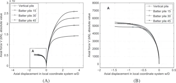
The results of the numerical simulations of axial compression and pull-out tests for vertical and batter piles (with
𝛽 = 15◦, 30◦, and 45◦) are shown in Figure 4 in terms of axial load vs normalized axial displacement curves (in the
FIGURE 3 Calculating the pull-out capacity of a batter pile (𝛽 = 15◦) with the asymptote-tangent method (local coordinate system)
FIGURE 4 Axial capacity: A, pull-out and bearing capacity of a vertical and batter piles (absolute values); B, zoom of pull-out region A (local coordinate system)
TABLE 2 Axial pull-out and bearing capacities of piles for different inclination angles
𝜷 𝟎◦∗
15◦ 30◦ 45◦
Vt0𝛽, kN −5.010 × 10³ −4.907 × 10³ −4.890 × 10³ −4.736 × 10³
Vc0𝛽, kN 2.590 × 10⁴ 2.280×10⁴ 1.940×10⁴ 1.430×10⁴
Table 2. It can be seen that the pull-out capacity is decreasing with increasing pile inclination. This is in accordance with experimental and numerical results found in the literature.5,10,11,15,18
Hanna and Afram10proposed the following relation for the axial pull-out capacity V
t0𝛽of batter piles, as a function of
the pull-out capacity of an identical vertical pile Vt0and of pile inclination𝛽 (in radians):
Vt0𝛽 =Vt0cos(𝜆−a𝛽) (1)
with𝜆−
a = 0.5. The results obtained from the pull-out simulations are compared with Equation 1 in Figure 5A. The
comparison shows a very good agreement between the FE results and the relation proposed by Hanna and Afram. From this figure, it can be also observed that the decrease in pull-out capacity with increasing𝛽 is relatively limited (less than 10%). This is due to the fact that the lateral shear strength at the soil-pile interface is not significantly affected by the pile inclination, for the range of𝛽 considered.
The computed values of the compression pile bearing capacity in Table 2 are also plotted as a function of the pile inclination𝛽 in Figure 5B. As for the pull-out capacity, the compression pile bearing capacity decreases with increasing
FIGURE 5 Computed axial capacity of batter piles for different inclination angles: A, normalized pull-out capacity vs Equation 1; B, normalized bearing capacity vs Equation 2 (local coordinate system)
FIGURE 6 Load vs normalized displacement curves of laterally loaded piles for different loading directions and inclination angles (local coordinate system)
𝛽. This time, however, the effect is stronger, as a reduction of the order of more than 40% at 𝛽 = 45◦ is observed. This
behavior can be explained considering that—different from the lateral strength—the pile tip bearing capacity is strongly affected by the inclination𝛽 since (1) in batter piles, the inclination of the base of the pile with respect to the horizontal axis is also equal to𝛽, and this may reduce the tip bearing capacity, as in shallow footings; (2) as 𝛽 increases, the depth of the pile tip decreases with cos𝛽, reducing the stabilizing contribution of the lateral surcharge load.
Similar to Equation 1, we propose to interpolate the FE simulations compression pile bearing capacities for varying𝛽 as
Vc0𝛽 =Vc0cos(𝜆+a𝛽), (2)
where𝜆+
a =1.35; Vc0𝛽 is the bearing capacity of a single batter pile in sand inclined by an angle𝛽, and Vc0is the bearing
of the same pile standing vertically; see Figure 5B.
2.4
Lateral resistance
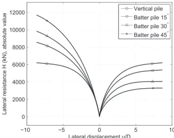
The numerical simulation results of lateral loading in both positive and negative x directions for vertical and batter piles (with𝛽 = 15◦, 30◦, and 45◦) are shown in Figure 6 as lateral load (absolute value) vs normalized lateral displacement curves (in the local coordinate system). The lateral resistance for the different piles is summarized in Table 3.
In can be seen in Figure 6 and Table 3 that the batter piles lateral resistance is greatly influenced by the pile inclination and the loading direction. For any given inclination𝛽 > 0, the lateral resistance of a pile submitted to a negative horizontal force (H≤ 0, reverse-battered) is larger than that of a forward-battered pile (H > 0). As suggested by Zhang et al,13this can
be explained considering that in reverse-battered piles, the pile horizontal movement causes a positive Δ𝜎vin the soil in
front of the pile (Figure 7, soil element 2). This, in turns, produces a net increase in the pile lateral resistance, as compared with a vertical pile. On the contrary, if the pile is forward-battered, the horizontal movement of the pile causes an upward movement of the soil and thus a negative Δ𝜎vin the soil in front of the pile (Figure 7, soil element 3). Thus, the lateral
resistance is smaller than that of a vertical pile. This is in accordance with experimental results found in the literature.12
TABLE 3 Lateral resistance of batter piles for different loading directions and inclination angles
𝛽 0◦∗ 15◦ 30◦ 45◦
H0𝛽, kN, H> 0 0.56 × 10⁴ 0.50 × 10⁴ 0.40 × 10⁴ 0.32 × 10⁴
H0𝛽, kN, H≤ 0 −0.56 × 10⁴ −0.68 × 10⁴ −0.88 × 10⁴ −1.10 × 10⁴
FIGURE 7 Pile inclination and loading direction effects on the stress state around the pile shaft (global (̄x, ̄𝑦, ̄z) and local (x, y, z) coordinate systems)
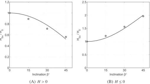
FIGURE 8 Computed normalized lateral resistance of batter piles for different inclination angles: comparison between FE results and Equation 3 for (A) forward-battered piles (H> 0) and (B) reverse-battered piles (H ≤ 0)
As for the pull-out and bearing capacities, the lateral resistances obtained in the FE simulations, as a function of the inclination𝛽 and the loading direction can be interpolated as
H0𝛽=
{
H0cos(𝜆+𝓁𝛽) if H > 0;
H0{2 − cos(𝜆−𝓁𝛽)} if H ≤ 0. (3)
Figure 8 shows that a good agreement can be obtained assuming the 2 scaling coefficients𝜆+𝓁 =1.3 and 𝜆− 𝓁 =2.0.
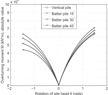
FIGURE 9 Overturning moment vs pile head rotation curves of laterally loaded piles for different loading directions and inclination angles
TABLE 4 Rotational resistance of batter piles for different loading directions and inclination angles
𝜷 𝟎◦∗
15◦ 30◦ 45◦
M0𝛽, kN, M > 0 0.45 × 10⁵ 0.48 × 10⁵ 0.50 × 10⁵ 0.58 × 10⁵
M0𝛽, kN, M ≤ 0 −0.45 × 10⁵ −0.42 × 10⁵ −0.40 × 10⁵ −0.38 × 10⁵
FIGURE 10 Computed normalized lateral resistance of batter piles for different inclination angles: comparison between FE results and Equation 4 for (A) forward-battered piles (M> 0) and (B) reverse-battered piles (M ≤ 0)
2.5
Rotational resistance
The numerical simulation results in both positive and negative z directions for vertical and batter piles (with𝛽 = 15◦, 30◦, and 45◦)are shown in terms of bending moment (in absolute value) vs pile head rotation (in the local reference frame) in Figure 9. The rotational resistances of the different piles are summarized in Table 4. Similar to the lateral resistance, pile inclination and loading direction have a considerable influence on the rotational resistance.
As before, the FE rotational resistances for varying inclinations𝛽 and loading directions can be interpolated as
M0𝛽=
{
M0{2 − cos(𝜆+m𝛽)} if M > 0;
M0cos(𝜆−m𝛽) if M≤ 0.
(4)
Figure 10 shows that a good agreement can be obtained assuming the 2 scaling coefficients𝜆+
m=1.0 and 𝜆−m=0.8.
The results of the FE simulations interpolated by Equations 1 to 4 play a central role in the development of the hypoplastic batter pile macroelement detailed in the following section.
3
H Y P O P L A ST I C M AC RO E L E M E N T FO R BAT T E R P I L E S
Based on the hypoplastic macroelement for single vertical piles in sand by Li et al58and the results presented in Section
2, an extension is proposed hereafter to take into account the effects of pile inclination and loading direction on the pile response. The macroelement introduced58is inspired from the work of Salciarini and Tamagnini39for shallow foundations
and adopts the “intergranular displacement” concept from Niemunis and Herle59to provide the model with sufficient
memory of the previous loading history to accurately reproduce the soil-pile system behavior under cyclic loading. In the following, the hypoplastic formulation of the macroelement for vertical piles is first briefly recalled. Then the analytical equations proposed in Section 2 are introduced in the expression describing the failure surface, the transforma-tion from the local to the global coordinate system is detailed, and finally, 3D FE simulatransforma-tions are used to test and validate the macroelement's performance.
3.1
Macroelement constitutive equations
The hypoplastic macroelement constitutive equations are developed hereafter in the local (x, y) coordinate system. For the particular case of𝛽 = 0 (vertical pile), the local coordinate system coincides with the global coordinate system. As in Li et al,58the response of the soil-pile system is described with a “lumped” constitutive equation between the generalized
load vector t and the generalized displacement vector u, defined as
t ∶= {V, H, M∕D}T u ∶= {w, u, D𝜃}T, (5)
where V, H, and M are the axial force, transversal force, and bending moment at the pile head; w, u, and𝜃 are the conju-gated displacements and rotation; and D is the pile diameter, used here as a characteristic length scale to homogenize the dimensions of the components of t and u.
The constitutive equation for a hypoplastic macroelement, written in rate—form to allow for nonlinear and irreversible responses—has the following basic structure39,58:
̇t = (t) ̇u + N(t)|| ̇u||, (6)
where the (3 × 3) matrix and the (3×1) vector N are constitutive functions, possibly depending on the current load level
t. In Equation 6, the first term on the right-hand side represents the incrementally linear part of the constitutive equation. The second term, nonlinear in ̇u, is responsible for the incremental nonlinearity of the system response.68,69After recasting
Equation 6 in a quasi-linear format, the hypoplastic equation reads
̇t = (t, 𝜼) ̇u, (7)
in which the tangent stiffness matrix is given by
= (t) + N(t)𝜼T 𝜼 ∶= ̇u
|| ̇u||. (8)
3.2
Definition of matrix
L
The constitutive matrix of Equation 6 is linked to the “pseudo-elastic” stiffness matrix eof the soil-pile system (under load reversal at very small displacement levels) by the relation
e =mR ⇐⇒ = 1 mR e = 1 mR [ kvv 0 0 0 khh khm 0 khm kmm ] , (9)
where kvv, khh, kmm, and khmare the axial, horizontal, rotational, and coupled horizontal-rotational stiffness coefficients
of the pile-soil system.
3.3
Definition of vector N
Following Niemunis,70the constitutive vector N of Equation 6 can be recast in the following form:
N(t) = −Y (t)m(t), (10)
where m is a unit vector and the scalar function Y(t) ∈ (0, 1] is a suitable loading function. With the assumption of Equation 10, the constitutive equation of the macroelement reads
̇t = { ̇u − Y(t)m|| ̇u||}. (11)
The loading function Y(t), which controls the degree of nonlinearity of the system response, increases monotonically with the distance of the current stress state t to the assumed ultimate failure surface of the soil-pile system:
F(t) = F(V, H, M∕D) = 0 (12)
in the generalized loading space.5,15,61,71-73
As in Li et al,58the loading function is defined as follows. For each loading state t inside the failure surface, an image
state t∗is defined on the failure surface by a simple projection from the origin of the loading space: t∗ = 1
𝜉t 𝜉 ∈ (0, 1]. (13)
The scalar multiplier𝜉 is obtained by imposing the condition F(t∗) =0. Taking𝜉 as a suitable measure of the distance
of the current loading state from the failure surface, we adopt the following simple power law for the loading function Y:
Y (t) =𝜉𝜅 (14)
with𝜅 a material constant controlling the stiffness decay of the model response upon monotonic loading paths at constant
𝜼. It is worth noting that, for any 𝜉 = const. < 1, the equation
𝑓(t) = F(t∕𝜉)|𝜉=const=0 (15)
defines a “loading surface” in loading space, which is homothetic to the failure surface, but of smaller size, and contains the current loading state t.
As far as the unit vector m, Li et al58have shown that for states inside the failure surface, m can be taken as the unit
gradient of the loading function f (unit normal to the loading surface):
m = g g = 1
||𝜕𝑓∕𝜕t||
𝜕𝑓
𝜕t. (16)
The rationale for this choice is that, as the loading state approaches failure ( ̇t → 𝟎 and Y → 1), m tends to the flow direction of the current collapse mechanism and also to the unit normal to the failure surface (associative flow rule):
m→ ( ̇u || ̇u|| ) 𝑓 =𝜼𝑓 m→ g𝑓 = 1 ||𝜕F∕𝜕t||𝜕F𝜕t, (17)
which provides an associative flow rule at failure. In practice, although the failure locus defined by Equation 12 rep-resents an attractor for the evolution Equation 11, the flow rule Equation 16 with f ≡ F does not guarantee that, for complex loading conditions, the loading path will never cross the failure surface, reaching states with F> 0 (or Y > 1). Therefore, to prevent the loading path to reach impossible states, the flow direction vector m in the close vicinity of the failure surface is defined by
m = v
||v|| v = [1 −s(Y, 𝜖)]g + s(Y, 𝜖)𝜼, (18)
wheresis a smoothed Heaviside step function defined as
s(Y, 𝜖) = ⎧ ⎪ ⎨ ⎪ ⎩ 0 for Y≤ 1 1 2 [ 1 − cos ( Y −1 𝜖 𝜋 )] for 1< Y ≤ 1 + 𝜖 1 for Y> 1 + 𝜖, (19)
with𝜖 a small regularizing coefficient. According to Equation 18, the flow direction m equals gfon the failure surface, while for states characterized by Y≥ 1+𝜖, m is set equal to 𝜼, thus forcing ̇t ≃ 0—see Equation 11. A smooth interpolation between these 2 limits is adopted in the region where Y ∈ (1, 1 + 𝜖). Experience indicates that in most circumstances, a value of𝜖 = 10−6is adequate.
3.4
Extension to cyclic loading
The basic form of the hypoplastic constitutive Equations 6 or 11 is suitable for monotonic loading. The current loading state being the only state variable, such formulation is however unable to keep memory of the previous loading history. Such feature is nevertheless necessary to reproduce realistically the behavior of the pile-soil system under cyclic load-ing. To overcome this limitation, following Salciarini and Tamagnini,39an additional internal variable called “internal
displacement”𝜹 is added to the set of the model state variables.
The internal displacement vector is equipped with the following evolution equation:
̇𝜹 = ̂(𝜹, 𝜼) ̇u =̂ { − 𝜌𝛽r𝜼
𝛿𝜼T𝛿 if𝜼𝛿·𝜼 > 0;
if𝜼𝛿·𝜼 ≤ 0. (20)
where is the (3 × 3) identity matrix, the quantities
𝜼𝛿∶= { 𝜹∕||𝜹|| (if||𝜹|| > 0) 0 (if||𝜹|| = 0) 𝜌 ∶= 1 R||𝜹|| (21)
provide the direction of𝜹 and a normalized measure of its magnitude, and 𝛽rand R are model constants. Equation 20 implies that, for sufficiently long monotonic displacement paths (𝜼 ≃ const, 𝜌 = 1), 𝜼𝛿 = 𝜼 and ̇𝜹 = 0, ie, 𝜹 is constant and tangent to the displacement trajectory. Under a sharp change in the displacement path direction (𝜼 · 𝜼𝛿 < 0), ̇𝜹 = ̇u and the internal displacement changes its direction to adapt to the new loading path.
With the incorporation of the additional state variable, the constitutive equations of the macroelement takes the format39,59 ̇t = ̂(t, 𝜹, 𝜼) ̇u, (22) where ̂ = [𝜌𝜒m T+ (1 −𝜌𝜒)mR](t) + ̃(t, 𝜹, 𝜼), (23) ̃ = { 𝜌𝜒(1 − m T)(𝜼𝛿)𝜼T𝛿 +𝜌𝜒N𝜼T𝛿 (if𝜼𝛿·𝜼 > 0) 𝜌𝜒(mR−mT)(𝜼 𝛿)𝜼T𝛿 (if𝜼𝛿·𝜼 ≤ 0), (24)
3.5
Failure surface for batter piles
For the specific case of single vertical pile in sand (Fontainebleau sand NE34), Li et al58,61proposed the following equation
for the failure surface (12), shown in Figure 11:
F(t) = ( H H0 )2 + ( DM DM0 )2 −𝛼 ( H H0 ) ( DM DM0 ) −1 + { (V) ( Vt0 Vc0 )2 +(−V) } ( V Vt0 )2 =0, (25)
where the constants H0, M0, Vc0, and Vt0represent the failure loads under pure horizontal, bending, axial compression,
and axial tension;𝛼 is a model constant controlling the orientation of the failure surface in the H ∶ M∕D plane, and (x) is the Heaviside step function, defined by
(x) = {
1 if x> 0 0 if x≤ 0 .
With this failure surface, the scalar multiplier𝜉 providing the distance of the current loading state to the failure surface has the closed form expression
𝜉 = √( H H0 )2 + ( DM DM0 )2 −𝛼 ( H H0 ) ( DM DM0 ) + ( V V0 )2 , (26)
where V0=Vc0for V> 0 and V0=Vt0otherwise, while the loading surface defined by Equation 15 is given by
𝑓(t) = ( H h0 )2 + ( DM Dm0 )2 −𝛼 ( H h0 ) ( DM Dm0 ) −1 + { (V) ( vt0 vc0 )2 +(−V) } ( V vt0 )2 =0, (27) where h0=𝜉H0≤ H0 m0=𝜉M0≤ M0 vc0=𝜉Vc0≤ Vc0 vt0=𝜉Vt0≤ Vt0. (28)
When the loading surface moves towards the failure surface, plasticity develops. The unit gradient of the loading surface
m = gis shown in Figure 12.
As shown in Section 2, the pile inclination and the loading direction affect the axial, lateral, and bending batter pile resistance. To take into account such effects in the failure and loading surfaces of the soil-pile system, Equations 25 and 27 are modified as follows:
F(t) = ( H H0𝛽 )2 + ( DM DM0𝛽 )2 −𝛼 ( H H0𝛽 ) ( DM DM0𝛽 ) −1 + { (V) ( Vt0𝛽 Vc0𝛽 )2 +(−V) } ( V Vt0𝛽 )2 =0, (29)
FIGURE 11 Failure surface of a single vertical pile in sand, Equation 25, after Li et al58,61[Colour figure can be viewed at
FIGURE 12 The unit gradient of the loading surface m, Equation 16 [Colour figure can be viewed at wileyonlinelibrary.com] 𝑓(t) = ( H h0 )2 + ( DM Dm0 )2 −𝛼 ( H h0 ) ( DM Dm0 ) −1 + { (V) ( vt0 vc0 )2 +(−V) } ( V vt0 )2 =0, (30) where h0=𝜉H0𝛽 ≤ H0𝛽 m0=𝜉M0𝛽≤ M0𝛽 vc0=𝜉Vc0𝛽 ≤ Vc0𝛽 vt0=𝜉 Vt0𝛽 ≤ Vt0𝛽 (31)
and the quantities Vc0𝛽, Vt0𝛽, H0𝛽, and M0𝛽are provided by Equations 1 to 4 of Section 2.
3.6
From the local to the global reference frame
All equations in Sections 3.1 to 3.5 have been developed in the local reference frame, see Figure 1. For the implementation of the macroelement in a general purpose FE software, it is however necessary to write them in the global reference frame. This is done considering that the transformation of the generalized force and displacement vectors and of their rates to the new reference frame are given by
t =t ̇t = ̇t u =u ̇u = ̇u 𝜹 = 𝜹 ̇𝜹 = ̇𝜹, (32)
where = [ cos𝛽 sin 𝛽 0 −sin𝛽 cos 𝛽 0 0 0 1 ] −1 =T (33)
is the orthogonal transformation matrix and𝛽 is the pile inclination angle. In the global reference frame, the macroele-ment constitutive Equation 22 takes thus the following form:
̇
t =(t, 𝜹, 𝜼) ̇u, where = T.̂ (34)
The numerical validation of the novel hypoplastic macroelement for single batter piles in sand is presented in Section 4.
4
N U M E R I C A L VA L I DAT I O N
The hypoplastic macroelement for single batter piles in sand presented in Section 3 has been implemented in the FE Matlab toolbox FedeasLab,74using an explicit integration scheme with automatic error control.58,75,76In the following, the
performance of the macroelement for a single batter pile is demonstrated comparing its response in a series of monotonic and cyclic loading tests with 3D nonlinear FE simulations.
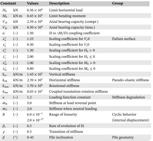
TABLE 5 Hypoplastic macroelement constants adopted in the simulations, after Li et al58
Constant Values Description Group
H0 kN 0.56 × 10⁴ Limit horizontal load
M0 kN·m 0.45 × 10⁵ Limit bending moment
Vc0 kN 2.59 × 10⁴ Axial bearing capacity (compr.)
Vt0 kN 0.50 × 10⁴ Axial bearing capacity (tens.)
𝛼 (–) 1.50 H vs. (M∕D)coupling coefficient
𝜆+
a (–) 1.35 Scaling coefficient for Vc0 Failure surface
𝜆−
a (–) 0.50 Scaling coefficient for Vt0
𝜆+
𝓁 (–) 1.30 Scaling coefficient for H0> 0
𝜆−
𝓁 (–) 2.00 Scaling coefficient for H0≤ 0
𝜆+
m (–) 1.00 Scaling coefficient for M0> 0
𝜆−
m (–) 0.80 Scaling coefficient for M0≤ 0
kvv kN/m 1.45 × 10⁵ Vertical stiffness
khh kN/m 2.39 × 10⁵ Horizontal stiffness Pseudo–elastic stiffness
kmm kN/m 3.70 × 10⁶ Rotational stiffness
khm kN/m 8.03 × 10⁵ Coupled translation-rotation stiffness
𝜅 (–) 1.2 Loading function constant Stiffness degradation
mR (–) 5.0 Stiffness at load reversal point
mT (–) 2.0 Stiffness when neutral loading
R (–) 6.0 × 10⁻³ Range of linearity Cyclic behavior 2.0 × 10⁻²a
(internal displacement)
𝛽r (–) 0.5 Rate of evolution of IS
𝜒 (–) 0.5 Transition of stiffness
𝛽 (◦) 0-45 Pile inclination Pile geometry
aValue adopted after cyclic loading simulations, obtained by trial and error. More advanced technique to
determine the parameters refers to Jin et al.77
FIGURE 13 Pile response to imposed axial displacement at fixed lateral displacement and rotation for different values of angle𝛽; A, FE simulation; B, macroelement predictions (local coordinate system)
The 3D nonlinear FE simulations adopt the von Wolffersdorff hypoplastic model63; details are provided in Section 2.
The macroelement constants are provided in Table 5, and the values of the scaling coefficients𝜆±a,𝜆±𝓁, and𝜆±mare given
in Section 2. With the only exception of the constant R, which has been finely tuned simulating cyclic loading tests, all the other constants coincide with those adopted for the macroelement for the vertical pile, provided by Li et al.58Therefore, the
4.1
Monotonic loading cases
Three monotonic loading cases are considered hereafter: (1) imposed axial displacement at fixed lateral displacement and rotation, (2) imposed lateral displacement at fixed axial displacement and rotation, and (3) imposed rotation at fixed axial and lateral displacements. For all load cases, simulations are performed considering different loading directions and pile inclinations ranging from 0◦(vertical pile) to 45◦.
Figures 13, 14, and 15 show the comparisons between FE and macroelement predictions for axial loading, lateral loading, and bending, respectively, in terms of generalized load-displacement curves (in the local reference frame) for different values of𝛽 and loading directions.
The comparisons between the FE simulations and the macroelement predictions are very good for almost all loading directions and pile inclinations. The most significant differences are the overestimation of the apparent horizontal stiff-ness and the underestimation of the horizontal pile resistance in Figure 14, for positive lateral displacements and large values of𝛽.
Given the dramatic increase in the computational efficiency provided by the macroelement as compared with the 3D nonlinear FE model, this result is quite encouraging. Furthermore, it implies that good predictions of the batter pile response can be obtained from the knowledge of the mechanical response of an identical vertical pile, ie, most of the material constants of the macroelement for batter piles are calibrated from data referring to the identical vertical pile. The macroelement is definitely an innovative numerical tool then can be used in engineering offices, under certain circumstances, for the design of vertical and batter piles.
FIGURE 14 Pile response to imposed lateral displacement at fixed axial displacement and rotation for different values of angle𝛽; A, FE simulation; B, macroelement predictions (local coordinate system)
FIGURE 15 Pile response to imposed rotation at fixed axial and lateral displacements for different values of angle𝛽; A, FE simulation; B, macroelement predictions (local coordinate system)
4.2
Cyclic loading cases
A series of cyclic horizontal numerical loading tests are performed hereafter on piles with inclination angles ranging from 0◦ (vertical pile) to 45◦. The tests are performed under horizontal displacement control, at fixed vertical displacement, with progressively increasing cyclic displacement amplitude.
FIGURE 16 Pile response to imposed horizontal cyclic displacements,𝛽 = 0◦; A, FE simulation; B, macroelement predictions (global coordinate system)
FIGURE 17 Pile response to imposed horizontal cyclic displacements,𝛽 = 15◦; A, FE simulation; B, macroelement predictions (global coordinate system)
FIGURE 18 Pile response to imposed horizontal cyclic displacements,𝛽 = 30◦; A, FE simulation; B, macroelement predictions (global coordinate system)
FIGURE 19 Pile response to imposed horizontal cyclic displacements,𝛽 = 45◦; A, FE simulation; B, macroelement predictions (global coordinate system)
Figures 16-18, and 19 show the comparison between the FE and macroelement predictions for vertical and batter piles with𝛽 = 15◦, 30◦, and 45◦ in terms of horizontal load vs normalized horizontal displacement in the global reference frame.
The results in Figures 16-18, and 19 indicate that, in general, the macroelement reproduces very well the 3D FE sim-ulations. In particular, the comparison is very good for the vertical pile and the pile with𝛽 = 15◦. For piles with more important inclinations, comparison is still satisfactory. The macroelement is able to capture the progressive increase of the hysteresis loops with increasing pile inclination𝛽. Finally, the macroelement computational efficiency is even more sig-nificant for cyclic than in monotonic loading cases: each simulation takes about 150 seconds (FedasLab74), while almost
48 hours are necessary for a 3D FE simulation performed with Abaqus Standard.62
5
CO N C LU S I O N S
In this paper, the hypoplastic macroelement model for single vertical piles in sand proposed by Li et al58has been modified
to reproduce the response of single batter piles with inclinations as large as 45◦. The extension to batter piles is incorpo-rated by a modification of the ultimate failure locus and of the loading surfaces in the generalized loading space, taking into account the variation of the ultimate failure loads in axial pull-out and compression, lateral loading, and bending with the inclination angle𝛽.
A striking feature of the novel batter pile macroelement is that a very good agreement can be achieved with nonlinear 3D FE simulations, using the majority of the parameters of the macroelement for an identical vertical pile.58The hypoplastic
macroelement for batter piles uses 6 additional scaling coefficients𝜆±a, 𝜆±𝓁, and𝜆±m, determined by a series of preliminary FE simulations. The fact that the value of𝜆−
aprovided by our numerical study coincides with the one reported by Hanna
and Afram10might suggest that the scaling coefficients are not affected by the pile length and diameter, as well as the soil
properties. However, further experimental and numerical investigations are necessary to clarify this point.
Last but not the least, the proposed macroelement is proven capable of reproducing the salient features of the soil-pile system response with a similar level of accuracy as nonlinear 3D FE simulations but with a dramatic reduction of the com-putational cost. This is particularly important for practical applications and design procedures in which the foundation is subjected to a large number of cycles, such as performance-based earthquake design or offshore engineering applications. Several shortcomings of the proposed macroelement should be also acknowledged. First of all, the current proposed approach lies in the impossibility of describing rate-dependent effects originating from hydro-mechanical coupling (ie, consolidation) in saturated soils, due to the “lumped” character of the constitutive equations of the macroelement. This could be of importance in some particular circumstances, such as piled foundations in fine sands under seismic loading conditions; see, eg, Martinelli and Tamagnini.78Currently, the proposed macroelement is developed for a long flexible
batter pile embedded in dense sand (Fontainebleau sand NE34). The pile rigidity (related to the pile diameter, length, sectional stiffness, and soil stiffness) and the pile section shape can influence the pile behavior. Furthermore, different soil conditions (clays, multilayered deposits) and the interactions between piles can change the failure locus and the loading surfaces. Further research studies are therefore needed to address these different points.
AC K N OW L E D G E M E N T S
Financial support from National Natural Science Foundation of China (NSFC, Grant No. 51708009) is highly acknowl-edged. The support of IFSTTAR (Institut français des sciences et technologies des transports, de l'aménagement et des réseaux) and of the Région Pays de la Loire is gratefully appreciated. The authors would like also to thank the valu-able support and help of the technical staff of the IFSTTAR centrifuge team. The first author would like to acknowledge Dr Hanliang Wu and Mr. Zhi Liu from the Research Institute of Highway in Beijing for sharing their knowledge in structural mechanics. The supports from Mr. Zhaochao Zhang and Ms. Chunxia Ke are also acknowledged by the first author.
O RC I D
Zheng Li http://orcid.org/0000-0002-2734-9419
Panagiotis Kotronis http://orcid.org/0000-0002-8978-1274
R E F E R E N C E S
1. Poulos HG, Davis EH. Pile Foundation Analysis and Design. New York: John Wiley and Sons, Inc.; 1980. 2. Reese LC, Van Impe WF. Single Piles and Pile Groups Under Lateral Loading, 2nd ed. CRC Press; 2011. 3. Eurocode7. Eurocode7: Geotechnical Design. Belgium: European Committee for Standardization (CEN); 2003.
4. Eurocode8-Part5. Eurocode 8: Design of Structures for Earthquake Resistance Part 5: Foundations, Retaining Structures and Geotechnical
Aspects. Belgium: European Committee for Standardization (CEN); 2003.
5. Meyerhof GG, Ranjan G. The bearing capacity of rigid piles under inclined loads in sand. II: Batter piles. Can Geotech J. 1973;10(1):71-85. https://doi.org/10.1139/t73-006.
6. Meyerhof GG, Ranjan G. The bearing capacity of rigid piles under inclined loads in sand. III: Pile groups. Can Geotech J. 1973;10(3):428-438. https://doi.org/10.1139/t73-036.
7. Meyerhof GG, Mathur SK, Valsangkar AJ. The bearing capacity of rigid piles and pile groups under inclined loads in layered sand. Can
Geotech J. 1981;18(4):514-519. https://doi.org/10.1139/t81-062.
8. Meyerhof GG, Yalcin AS. Behaviour of flexible batter piles under inclined loads in layered soil. Can Geotech J. 1993;30(2):247-256. https:// doi.org/10.1139/t93-021.
9. Meyerhof GG, Yalcin AS. Bearing capacity of flexible batter piles under eccentric and inclined loads in layered soil. Can Geotech J. 1994;31(4):583-590. https://doi.org/10.1139/t94-068.
10. Hanna AM, Afram A. Pull-out capacity of single batter piles in sand. Can Geotech J. 1986;23(3):387-392. https://doi.org/10.1139/t86-054. 11. Nazir A, Nasr A. Pullout capacity of batter pile in sand. J Adv Res. 2013mar;4(2):147-154. https://doi.org/10.1016/j.jare.2012.04.001. 12. Zhang LM, McVay MC, Lai PW. Centrifuge modelling of laterally loaded single battered piles in sands. Can Geotech J.
1999;36(6):1074-1084.https://doi.org/10.1139/t99-072.
13. Zhang LM, McVay MC, Han SJ, et al.. Effects of dead loads on the lateral response of battered pile groups. Can Geotech J. 2002;39(3):561-575. https://doi.org/10.1139/t02-008.
14. Escoffier S, Chazelas JL, Garnier J. Centrifuge modelling of raked piles. Bull Earthq Eng. 2008;6(4):689-704. https://doi.org/10.1007/ s10518-008-9094-1.
15. Li Z. Experimental and numerical study of deep foundations under seismic loading: vertical piles and inclined piles. PhD Thesis: Ecole Centrale de Nantes; 2013. https://hal.archives-ouvertes.fr/tel-01095508.
16. Li Z, Escoffier S, Kotronis P. Centrifuge modeling of batter pile foundations under sinusoidal dynamic excitation. Bull Earthq Eng. 2016;14(3):673-697. https://doi.org/10.1007/s10518-015-9859-2.
17. Li Z, Escoffier S, Kotronis P. Centrifuge modeling of batter pile foundations under earthquake excitation. Soil Dyn Earthq Eng. 2016;88:176-190. https://doi.org/10.1016/j.soildyn.2016.05.013.
18. Mroueh H, Shahrour I. Numerical analysis of the response of battered piles to inclined pullout loads. Int J Numer Anal Methods Geomech. 2009;33(10):1277-1288. https://doi.org/10.1002/nag.765.
19. Padrón LA, Suárez A, Aznárez JJ, Maeso O. Kinematic internal forces in deep foundations with inclined piles. Earthquake Engineering &
Structural Dynamics. 2015;44(12):2129-2135. https://doi.org/10.1002/eqe.2559.
20. Giannakou AK. Seismic Behavior of Inclined Piles. PhD Thesis: National Technical University of Athens; 2007.
21. Gerolymos N, Giannakou A, Anastasopoulos I, Gazetas G. Evidence of beneficial role of inclined piles: observations and summary of numerical analyses. Bull Earthq Eng. 2008;6(4):705-722. https://doi.org/10.1007/s10518-008-9085-2.
22. Sadek M, Isam S. Three-dimensional finite element analysis of the seismic behavior of inclined micropiles. Soil Dyn Earthq Eng. 2004;24(6):473-485. https://doi.org/10.1016/j.soildyn.2004.02.002.
23. Isam S, Hassan A, Mhamed S. 3D elastoplastic analysis of the seismic performance of inclined micropiles. Comput Geotech. 2012;39:1-7. https://doi.org/10.1016/j.compgeo.2011.08.006.
24. Sadek M, Shahrour I. Influence of the head and tip connection on the seismic performance of micropiles. Soil Dyn Earthq Eng. 2006;26(5):461-468. https://doi.org/10.1016/j.soildyn.2005.10.003.
25. Dezi F, Carbonari S, Morici M. A numerical model for the dynamic analysis of inclined pile groups. Earthq Eng Struct Dyn. 2016;45(1):45-68. https://doi.org/10.1002/eqe.2615.
26. Awoshika K, Reese LC. Analysis of foundation with widely-spaced batter piles, Research Report 117-3F, Center for Highway Research, The University of Texas at Austin; 1971.
27. Kubo K. Experimental study of the behaviour of laterally loaded piles. Proceeding of the 6th International Conference on Soil Mechanics and Foundation Engineering; 1965; Canada:275-279.
28. Nova R, Montrasio L. Settlements of shallow foundations on sand. Geotéchnique. 1991;41(2):243-256. https://doi.org/10.1680/geot.1991. 41.2.243.
29. Montrasio L, Nova R. Settlements of shallow foundations on sand: geometrical effects. Geotéchnique. 1997;47(1):49-60.
30. Gottardi G, Houlsby GT, Butterfield R. Plastic response of circular footings on sand under general planar loading. Géotechnique. 1999;49(4):453-469.
31. Martin CM, Houlsby GT. Combined loading of spudcan foundations on clay: numerical modelling. Géotechnique. 2001;51(8):687-699. https://doi.org/10.1680/geot.2001.51.8.687.
32. Le Pape Y, Sieffert JG. Application of thermodynamics to the global modelling of shallow foundations on frictional material. Int J Numer
Anal Methods Geomech. 2001;25(14):1377-1408. https://doi.org/10.1002/nag.186.
33. Cassidy MJ, Byrne BW, Houlsby GT. Modelling the behaviour of circular footings under combined loading on loose carbonate sand.
Geotéchnique. 2002;52(10):705-712. https://doi.org/10.1680/geot.2002.52.10.705.
34. Paolucci R. Simplified evaluation of earthquake-induced permanent displacements of shallow foundations. J Earthq Eng. 1997;1(3):563-579. https://doi.org/10.1080/13632469708962378.
35. Crémer C, Pecker A, Davenne L. Cyclic macro-element for soil-structure interaction: material and geometrical non-linearities. Int J Numer
Anal Methods Geomech. 2001;25(13):1257-1284. https://doi.org/10.1002/nag.175.
36. Crémer C, Pecker A, Davenne L. Modelling of nonlinear dynamic behaviour of a shallow strip foundation with macro-element. J Earthq
Eng. 2002;6(2):175-211. https://doi.org/10.1080/13632460209350414.
37. Grange S, Kotronis P, Mazars J. A macro-element to simulate 3D soil-structure interaction considering plasticity and uplift. Int J Solids
and Struct. 2009;46(20):3651-3663. https://doi.org/10.1016/j.ijsolstr.2009.06.015.
38. Grange S, Kotronis P, Mazars J. A macro-element to simulate dynamic soil-structure interaction. Eng Struct. December 2009;31(12):3034-3046. https://doi.org/10.1016/j.engstruct.2009.08.007.
39. Salciarini D, Tamagnini C. A hypoplastic macroelement model for shallow foundations under monotonic and cyclic loads. Acta Geotechn. 2009;4(3):163-176. https://doi.org/10.1007/s11440-009-0087-2.
40. Gajan S. Physical and numerical modeling of nonlinear cyclic load-deformation behavior of shallow foundations supporting rocking shear walls. PhD Thesis: University of California, Davis; 2006.
41. Chatzigogos CT, Pecker A, Salençon J. Macroelement modeling of shallow foundations. Soil Dyn Earthq Eng. May 2009;29(5):765-781. https://doi.org/10.1016/j.soildyn.2008.08.009.
42. Shirato M, Paolucci R, Kouno T, Nakatani S, Fukui J, Nova R, di Prisco C. Numerical simulation of model tests of pier-shallow foundation systems subjected to earthquake loads using an elasto-uplift-plastic macro element. Soils and Found. 2009;48(5):693-711.
43. Gajan S, Kutter BL. Contact interface model for shallow foundations subjected to combined cyclic loading. J Geotech Geoenviron Eng. 2009;135(3):407-419.
44. Figini R, Paolucci R, Chatzigogos CT. A macro-element model for non-linear soil- shallow foundation-structure interaction under seis-mic loads : theoretical development and experimental validation on large scale tests. Earthquake Engineering and Structural Dynaseis-mics. 2012;41(3):475-493. https://doi.org/10.1002/eqe.1140.
45. Grange S, Botrugno L, Kotronis P, Tamagnini C. The effects of soil-structure interaction on a reinforced concrete viaduct. Earthq Eng
Struct Dyn. 2011;40(1):93-105. https://doi.org/10.1002/eqe.1034.
46. Venanzi I, Salciarini D, Tamagnini C. The effect of soil–foundation–structure interaction on the wind-induced response of tall buildings.
Engineering Structures. 2014;79:117-130. https://doi.org/10.1016/j.engstruct.2014.08.002.
47. Foglia A, Gottardi G, Govoni L, Ibsen LB. Modelling the drained response of bucket foundations for offshore wind turbines under general monotonic and cyclic loading. Appl Ocean Res. 2015;52:80-91. https://doi.org/10.1016/j.apor.2015.04.005.
48. Wood DM. Macroelement Modelling. In: di Prisco C, Wood DM, eds. Mechanical Behavior of Soils Under Environmentally Induced Cyclic
Loads. NewYork: Springer Wien; 2012:399-439.
49. di Prisco C. Cyclic mechanical response of rigid bodies interacting with sand strata. In: di Prisco C, Wood DM, eds. Mechanical Behavior
of Soils Under Environmentally Induced Cyclic Loads. NewYork: Springer Wien; 2012:363-398.
50. Grange Stéphane, Salciarini Diana, Kotronis Panagiotis, Tamagnini Claudio. A comparison of different approaches for the modelling of shallow foundations in seismic soil-structure interaction problems. In: Benz T, Nordal S, eds. Numerical Methods in Geotechnical
Engineering. Trondheim, Norway; 2010:405-410.
51. Salciarini D, Tamagnini C, Grange S, Kotronis P. La modellazione dei fenomeni di interazione terreno struttura mediante macroelementi: Elastoplasticità vs. ipoplasticità. Rivista Italiana di Geotecnica. 2010;4:9-28. http://www.associazionegeotecnica.it/sites/default/files/rig_ 410_09.pdf.
52. Marchi M, Butterfield R, Gottardi G, Lancellotta R. Stability and strength analysis of leaning towers. Géotechnique. 2011;61(12):1069-1079. https://doi.org/10.1680/geot.9.P.054.
53. Lancellotta R. La torre Ghirlandina: Una storia di interazione strutturaterreno. XI Croce Lecture. Rivista Italiana di Geotecnica. 2013;2:7-37. (in Italian).
54. Pisanò F, Di Prisco CG, Lancellotta R. Soil–foundation modelling in laterally loaded historical towers. Géotechnique. 2014;64(1):1-15. https://doi.org/10.1680/geot.12.P.141.
55. Pisanò F, Flessati L, Di Prisco C. A macroelement framework for shallow foundations including changes in configuration. Géotechnique. 2016;66(11):910-926. https://doi.org/10.1680/jgeot.16.P.014.
56. Correia AA, Pecker A, Kramer SL, Pinho R. Nonlinear pile-head macro-element model: SSI effects on the seismic response of a monoshaft-supported bridge. In: 15th World Conference on Earthquake Engineering; 2012:1-10.
57. Correia AA. A Pile-Head Macro-Element Approach to Seismic Design of Monoshaft-Supported Bridges. PhD Thesis: ROSE School Università degli Studi di Pavia & Istituto Universitario di Studi Superiori; 2011.
58. Li Z, Kotronis P, Escoffier S, Tamagnini C. A hypoplastic macroelement for single vertical piles in sand subject to three-dimensional loading conditions. Acta Geotechnica. 2016;11(2):373-390. https://doi.org/10.1007/s11440-015-0415-7
59. Niemunis A, Herle I. Hypoplastic model for cohesionless soils with elastic strain range. Mech Cohesive-frictional Mater. 1997;2(4):279-299. https://doi.org/10.1002/(SICI)1099-1484(199710)2:4<279::AID-CFM29>3.0.CO;2-8.
60. Meyerhof GG, Ranjan G. The bearing capacity of rigid piles under inclined loads in sand. I: Vertical piles. Can Geotech J. 1972;9(4):430-446. https://doi.org/10.1139/t72-043.
61. Li Z, Kotronis P, Escoffier S. Numerical study of the 3D failure envelope of a single pile in sand. Comput Geotech. 2014;62:11-26. Johnston, RI 02919, United States. https://doi.org/10.1016/j.compgeo.2014.06.004.
62. Abaqus/Standard. Abaqus 6.10 Documentation (SIMULIA Abaqus 6.10). Johnston, RI 02919, United States: Dassault Systèmes; 2010. 63. von Wolffersdorff PA. A hypoplastic relation for granular materials with a predefined limit state surface. Mech Cohesive-Frictional Mater.
1996;1(3):251-271. https://doi.org/10.1002/(SICI)1099-1484(199607)1:3<251::AID-CFM13>3.0.CO;2-3.
64. Gudehus G, Amorosi A, Gens A, et al. The soilmodels.info project. Int J Numer Anal Methods Geomech. 2008;32(12):1571-1572. https:// doi.org/10.1002/nag.675.
65. Verdure L, Garnier J, Levacher D. Lateral cyclic loading of single piles in sand. Int J Phys Model Geotech. 2003;3(3):17-28. https://doi.org/ 10.1680/ijpmg.2003.030303.
66. Rosquoët F. Pile under lateral cyclic load. PhD Thesis: Ecole Centrale de Nantes & Université de Nantes; 2004.
67. Rosquoët F, Thorel L, Garnier J, Canepa Y. Lateral cyclic loading of sand-installed piles. Soils Found. 2007;47(5):821-832. https://doi.org/ 10.3208/sandf.47.821.
68. Darve F. Une formulation incrémentale des lois rhéologiques. Application aux sols. PhD Thesis: INP Grenoble; 1978.
69. Tamagnini C, Viggiani G, Chambon R. A review of two different approaches to hypoplasticity. In Constitutive Modelling of Granular
Materials. Berlin, Heidelberg, New York: Springer; 2000:107-145.
70. Niemunis A. Extended hypoplastic models for soils. PhD Thesis: Bochum University; 2002.
71. Zafeirakos A, Gerolymos N. Bearing strength surface for bridge caisson foundations in frictional soil under combined loading. Acta
Geotech. 2016;11(5):1189-1208. https://doi.org/10.1007/s11440-015-0431-7.
72. Achmus M, Thieken K. On the behavior of piles in non-cohesive soil under combined horizontal and vertical loading. Acta Geotech. 2010;5(3):199-210. https://doi.org/10.1007/s11440-010-0124-1.
73. Conte E, Troncone A, Vena M. Behaviour of flexible piles subjected to inclined loads. Comput Geotech. 2015;69:199-209. https://doi.org/ 10.1016/j.compgeo.2015.05.009.
74. Filippou FC, Constandines M.. FedeasLab Getting Started Guide and Simulations Examples. PhD Thesis. Berkeley, CA: University of California; 2004.
75. Sloan SW. Substepping schemes for the numerical integration of elastoplastic stressâstrain relations. Int J Numer Methods Eng. 1987;24(5):893-911. https://doi.org/10.1002/nme.1620240505.
76. Sloan SW, Abbo AJ, Sheng D. Refined explicit integration of elastoplastic models with automatic error control. Eng Comput. 2001;18(1/2):121-154. https://doi.org/10.1108/02644400110365842.
77. Jin YF, Yin ZY, Shen SL, Hicher PY. Selection of sand models and identification of parameters using an enhanced genetic algorithm. Int
J Numer Anal Methods Geomech. 2016;40:1219-1240. https://doi.org/10.1002/nag.2487.
78. Martinelli M, Tamagnini C. Modeling SSI on piled foundations: the effects of kinematic interaction, ALERT 2013. Technical Report, Aussois; 2013.

![FIGURE 11 Failure surface of a single vertical pile in sand, Equation 25, after Li et al 58 , 61 [Colour figure can be viewed at wileyonlinelibrary.com]](https://thumb-eu.123doks.com/thumbv2/123doknet/7763936.255594/13.892.127.809.752.1043/figure-failure-surface-single-vertical-equation-colour-wileyonlinelibrary.webp)
![FIGURE 12 The unit gradient of the loading surface m, Equation 16 [Colour figure can be viewed at wileyonlinelibrary.com]](https://thumb-eu.123doks.com/thumbv2/123doknet/7763936.255594/14.892.295.601.81.250/figure-gradient-loading-surface-equation-colour-figure-wileyonlinelibrary.webp)