Design Procedure of a Nonlinear Vibration Absorber
Using Bifurcation Analysis
R. Viguié
(1), G. Kerschen
(1)(1) Structural Dynamics Research Group Aerospace & Mechanical Engineering Department
University of Liège, Liège, Belgium
E-mail: r.viguie,m.peeters,g.kerschen,jc.golinval@ulg.ac.be
ABSTRACT
A nonlinear energy sink (NES) is characterized by its ability to passively realize targeted energy transfer as well as multimodal damping. This latter feature seems to make this device very well suited for reducing the vibration level of MDOF linear structures. The perspective of dealing with MDOF linear primary structures requires the development of an efficient NES design procedure. This paper poses the basis of such a procedure based upon the bifurcation analysis of a system composed of a linear oscillator coupled to a NES, using the software MatCont.
1 INTRODUCTION
Passive vibration mitigation of mechanical structures is often associated to the famous Tuned Mass Damper (TMD) developed by Frahm[1]and Den Hartog[2]. Due to its linear character, the design of this absorber relies on a solid theoretical basis, possesses very-well known properties such as its capability to mitigate one mode of the primary structure, the trade-off existing between its performance and robustness levels or the introduction of a second resonant frequency. Even though the TMD design is very simple, these properties pose serious questions when several modes of the structures have to be damped out or when the system is submitted to mistuning. A recent body of literature has addressed these limitations using a nonlinear energy sink (NES) [3−14]. The concept of essential nonlinearity is central, because it means that an NES has no preferential resonant frequency, which makes it a frequency-independent absorber. Another salient feature of an NES is its capability to realize targeted energy transfer (TET) during which energy initially induced in the primary system gets passively and irreversibly transferred to the NES. Therefore, this nonlinear device seems to be very well suited for vibration isolation of MDOF linear structures or nonlinear structures.
Because of the strongly nonlinear character of the NES, the seek of an optimal design procedure is a challenging problem. A couple of researches tried to face this issue by considering numerically performed parametric studies with different objective functions such as the suppression of the self-sustained oscillations[15, 16], the amount of energy dissipated in the nonlinear absorber[17]or the time required for a complete energy dissipation[18]. Even though these parametric studies generally give good results, their related computational burden may be prohibitive. Therefore, more recent studies aimed to alleviate this cost either by properly extrapolating some concepts of the TMD tuning procedure to the NES ([19]) either by developing a NES design procedure based on the occurrence of quasiperiodic or beating motion ([20−22]). In both cases, excitation conditions differ as free and forced response motion is considered in the first and latter case, respectively.
In this paper, an new design procedure of the NES, based on the analysis of bifurcation points, is investigated. This procedure is devoted to any kind of structure composed of a primary system (SDOF and MDOF linear or nonlinear) coupled to a NES.
The first section describes the concept as well as the system considered to illustrate the procedure. The analysis of the related results is performed in section 2 and a particular application to the drill-string system is tackled in section 3. Finally, the last section deals with the concluding remarks and future work.
2 NONLINEAR TWO DEGREE-OF-FREEDOM SYSTEM
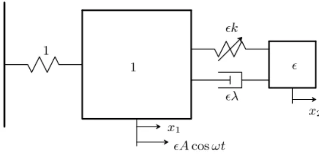
In this section, the context of the design procedure is explained. To this end, a 2DOF nonlinear system (figure 1) composed of a linear oscillator coupled to a NES is considered with a harmonic excitation applied to the linear oscillator. The dynamics of this system has already been widely discussed in[20−22]where the authors considered asymptotical methods to study the evolution of the slow flow and thereby assess a proper tuning procedure of the parameters leading to periodic motion of the envelope also known as quasiperiodic motion of the fast flow. It has been evidenced the occurrence of two types of such motions, namely, weakly quasiperiodic and strongly modulated (SMR) regimes. The first mentioned emanates from a loss of stability of the periodic motion characterized by a secondary Hopf bifurcation (also know as Neimarck-Sacker bifurcation) whereas the last one is accompanied by a relaxation type of oscillation. The realization of any of these motions has been proved to be preferable than periodic motion as they offer a larger reduction of the total system energy (kinetic + potential). Therefore, the seek of such regimes of a beating response consists in the objective function for the tuning procedure of the NES. For additional details on this subject, the interested reader may refer to the aforementioned references.
ǫk 1 ǫλ 1 ǫ x1 x2 ǫA cos ωt
Figure 1: Linear oscillator coupled to a NES
In order to ease the comparison process with the studies performed in[20−22], the same notations are considered and the equations of motion of the system depicted in figure 1 are given by :
¨
x1+ ǫλ( ˙x1− ˙x2) + x1+ ǫk(x1− x2)3 = ǫA cos ωt (1)
ǫ¨x2+ ǫλ( ˙x2− ˙x1) + ǫk(x2− x1)3 = 0
In those studies, asymptotical methods are considered and to simplify the tuning procedure, some assumptions are made on the system definition such as :
• the excitation frequency that is imposed to be equal to the linear natural frequency of the linear oscillator (ω = 1). • the forcing amplitude that is supposed to be low to ensure both motions of the linear oscillator and the NES to be
compa-rable.
• the optimization that is performed in the vicinity of the resonance1 : 1which restricts the number of possible solutions to
one stable periodic and one quasiperiodic attractor.
nonlinear stiffness, their use is restricted to limited size systems. In this context the development of a complementary tuning procedure is of interest to overcome these limitations.
3 CONCEPT OF BIFURCATION ANALYSIS
The characterization of the dynamics related to a nonlinear system is usually performed by computing a bifurcation diagram with respect to one or two system parameters. These continuation procedures are said to be of codimension one or two, respectively. Considering a system submitted to a harmonically forced excitation, its nonlinear frequency response function (NL-FRF) can be seen as a particular type of bifurcation diagram with the frequency of excitation playing the part of the bifurcation parameter. The computation of the system NL-FRF is usually numerically performed using shooting techniques associated to continuation procedures. Algorithms for the numerical continuation of periodic solutions are really quite sophisticated and advanced (see,e.g., [23−26], and the AUTO and MATCONT softwares). These algorithms have been extensively used for computing the forced response and limit cycles of nonlinear dynamical systems [27−32]. Doedel and co-workers used them for the computation of periodic orbits during the free response of conservative systems[33−35].
In this study the software used for the continuation procedure is MATCONT[36]. Several version of MATCONT exist, a GUI version, a command line version and a command line version for MAPS. In the present analysis as the system is harmonically forced, the command line version for MAPS is considered. To this end, the following change of variable :
ωt = τ (2)
has to be applied to system of equations 2 so that the forcing frequency be can be considered by the software as a bifurcation parameter and it comes :
ω2x′′1 + ωǫλ(x ′ 1− x ′ 2) + x1+ ǫk(x1− x2)3 = ǫA cos τ (3) ω2ǫx′′2 + ωǫλ(x ′ 2− x ′ 1) + ǫk(x2− x1)3 = 0
where the symbol " ’ " represents the differentiation with respect to the new variableτ. As the frequency becomes a system parameter, the time span in the integration procedure (that should be one period timeT) always keeps the same [0 2π]. After these practical considerations, let us consider the following initial set of system parameters :
Parameter Value Unit
A 0.3 [N ]
k 15 [N/m3]
λ 0.4 [N s/m]
ǫ 0.1
TABLE 1: Initial set of parameters
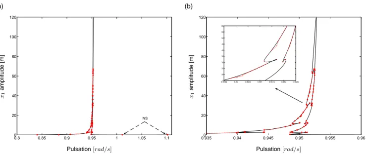
Performing the continuation with respect to the forcing frequency, the corresponding NL-FRF, for the primary system, is computed and depicted in Figure 2. This picture exhibits a high complexity level in terms of bifurcation points (red dots) and consequently coexisting solutions (among which, the red dashed lines corresponding to branches of periodic solutions computed with a branch point bifurcation as initial guess). As a detailed analysis of this NL-FRF is beyond the scope of the present study, for the seek of clarity, all possible coexisting solutions or stability information have not been represented herein. However, it can be mentioned the occurrence of 4 bifurcations types :
2. limit point : periodic motion that possesses one Floquet multipliers leaving the unit circle through1. This corresponds to the coexistence of 3 different solutions.
3. period doubling : periodic motion that possesses one Floquet multipliers leaving the unit circle through−1. This corre-sponds to the apperance of a doubled period solution.
4. Neimark-Sacker : periodic motion that possesses a pair of conjugated Floquet multipliers leaving the unit circle. This is also known as a secondary Hopf bifurcation (of the slow flow) and corresponds to the appearance of quasiperiodic motion.
0.8 0.85 0.9 0.95 1 1.05 1.1 0 20 40 60 80 100 120 Pulsation[rad/s] x1 a m p lit u d e [m ] 0.9350 0.94 0.945 0.95 0.955 0.96 20 40 60 80 100 120 0.949515 0.95 0.9505 0.951 0.9515 0.952 0.9525 20 25 30 35 40 45 50 55 60 Pulsation[rad/s] x1 a m p lit u d e [m ] (a) (b) NS
Figure 2: (a) NL-FRF of the 2DOF nonlinear system (figure 1) with parameters of table 3, evaluated at the primary system. / (b) Close-up of this NL-FRF. The red dots correspond to bifurcation points whereas the red dashed line
correspond to additional periodic solutions emanating from branch points.
0.8 0.85 0.9 0.95 1 1.05 1.1 0 2 4 6 8 10 12 14 16 18 Pulsation[rad/s] x1 a m p lit u d e [m ] NS LP LP
Figure 3: NL-FRF of the 2DOF nonlinear system (figure 1) with parameters of table 3 and k = 5 [N/m3], evaluated at the primary system. The red dots correspond to bifurcation points whereas the red dashed line correspond to additional
Now, considering the set of parameter tabulated in Table 3 but with a nonlinear stiffness beingk = 5 [N/m3], the related NL-FRF is depicted in Figure 3. Comparing this result with the previous one leads to some major comments :
1. the computational time is lower due to the much simpler response of the system (reduction of the singularities).
2. the appearance of loops in the NL-FRF consists in the main drawback as it is not necessarily clear to suspect their presence a priori, without any pre-analytical analysis.
An interesting feature is worth being noticed : for an increasing nonlinear character of the system, complementary isolated loops appear while already existing ones are growing. Furthermore, given some nonlinear levels these loops merge to finally converge toward the NL-FRF shape depicted in Figure 2.
Because these NL-FRF only represent two possible configurations of the system, other NL-FRF are required to seek optimal values for the NES. This procedure imposes the discretization of the design parameter space to be small enough to catch all the relevant information. However, taking into account the complexity of the system dynamical response, the computational cost is revealed to be too high and therefore, prohibitive.
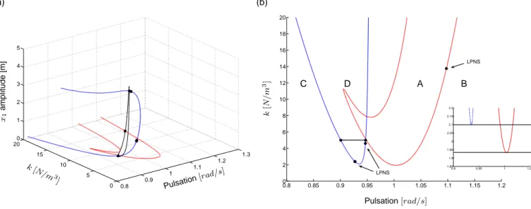
In this context, a computational time efficient methodology has to be addressed. The initial step lies in defining an objective (function) by wondering what the desired solutions types for the investigated system are. In the present study and based on the development carried out in[20−22]it is obvious that periodic motion is desired. It is also well known that (weak) quasi-periodic motion appears at a Neimarck-Sacker bifurcation which consists in the relevant information of the NL-FRF. Therefore, the objective results in the computation of a border that delimits the regions of periodicity and quasi-periodicity. To this end, based on a NS bifurcation point previously computed with the NL-FRF, a codimension two continuation is performed with respect to the forcing frequency as well as anyone of the design parameters such as, for example, the nonlinear stiffness k. This procedure gives rise to a curve in a 3D space (figure 4(a)) whose projection in the 2D plane (ω,k) (figure 4(b)) clearly puts forward two different motion type regions, A and B, corresponding to quasiperiodic and periodic responses, respectively. Note that a codimension 2 bifurcation point appears, namely a LPNS (Limit Poin - Neimarck Sacker) where both limit point curve and neimarck-sacker curve merges. This kind of point can be used to start another NS continuation.
0.8 0.9 1 1.1 1.2 1.3 0 5 10 15 200 0.1 0.2 0.3 0.4 0.5 Pulsation [rad/s] k [N/m 3 ] x1 a m p lit u d e [m ] 0.8 0.85 0.9 0.95 1 1.05 1.1 1.15 1.2 0 2 4 6 8 10 12 14 16 18 20 Pulsation[rad/s] k [N / m 3] (a) (b) A B LPNS
Figure 4: (a) 3D plot of the codimension 2 continuation of Neimarck-Sacker bifurcation points/ (b) Projection in the plane (ω,k). The red solid and the black dotted lines correspond to the Neimarck-Sacker bifurcation continuation and parts of the NL-FRF (figures 2 and 3), respectively. The black dots depict the location of NS and codimension 2 (LPNS)
bifurcation points.
The presence, in the working frequency range, of additional solutions associated to larger amplitude motions has to be avoided to insure performance and robustness to the absorber. To this end, it is of interest to reproduce a codimension two continuation
of limit point bifurcations with respect to the same continuation parameters. Once again a 3D curve is computed (figure 5(a)) and its projection in the 2D plane (ω,k) (figure 5(b)) defines two distinct regions, C and D, where one or multiple solutions exists. Finally, considering all those results, the region of interest is restricted tok= [1.931 2.098][N/m3]and delimited by black lines in figure 5(b). 0.8 0.9 1 1.1 1.2 1.3 0 5 10 15 200 1 2 3 4 5 Pulsation [rad/s] k [N/m 3 ] x1 a m p lit u d e [m ] 0.8 0.85 0.9 0.95 1 1.05 1.1 1.15 1.2 0 2 4 6 8 10 12 14 16 18 20 0.9 0.95 1 1.05 1.85 1.9 1.95 2 2.05 2.1 2.15 2.2 Pulsation[rad/s] k [N / m 3] (a) (b) A B C D LPNS LPNS
Figure 5: (a) 3D plot of the codimension 2 continuation / (b) Projection in the plane (ω,k). The blue, red solid and the black dotted lines correspond to the Limit Point, Neimarck-Sacker bifurcation continuation and parts of the NL-FRF
(figure 3), respectively. The black dots depict the location of LP and codimension 2 (LPNS) bifurcation points.
0.8 0.9 1 1.1 1.2 1.3 0 5 10 15 200 5 10 15 20 Pulsation [rad/s] k [N/m 3 ] x1 a m p lit u d e [m ] 0.8 0.85 0.9 0.95 1 1.05 1.1 1.15 1.2 0 2 4 6 8 10 12 14 16 18 20 0.9 0.95 1 1.05 1.85 1.9 1.95 2 2.05 2.1 2.15 2.2 Pulsation[rad/s] k [N / m 3] (a) (b) LPNS LPNS
Figure 6: (a) 3D plot of the codimension 2 continuation / (b) Projection in the plane (ω,k). The blue, red solid and the black dotted lines correspond to the Limit Point, Neimarck-Sacker bifurcation continuation and parts of the NL-FRF
(figure 3), respectively. The black dots depict the location of LP and codimension 2 (LPNS) bifurcation points.
However pushing further on the analysis to the continuation of an other limit point, it appears that there does not exist a region with only quasiperiodic attractor anymore (figure 6). Therefore this current continuation is stopped and no other bifurcation point analysis should be undertaken until the mass or damping coefficient of the absorber are reviewed.
This section aimed to present the concept of a NES design procedure based on bifurcation analysis. To this end, a given 2DOF nonlinear system has been considered but was not so realistic due to the lack of dissipation in the primary structure. This may probably be one of the origins of the complex dynamical response of the system observed in the NL-FRFs. In the next section, the design of a NES coupled to a more realistic structure, namely, a drill-string system, is investigated.
4 DESIGN OF A NES COUPLED TO THE DRILL-STRING SYSTEM
In [16], the use of passive nonlinear targeted energy transfer was considered to stabilize drill-string systems. To this end, a parametric study was performed to determine a set of absorber parameters leading to a significant improvement of the dynamical behavior. In this section, the aim lies in checking the quality of the set of absorber parameter and its closeness to the optimum. Herein, only a brief reminder on the problematic is presented and for more details on the subject, the interested reader may refer to the aforementioned study.
4.1 Problem description
Torsional vibration of the drill strings used in drilling oil and gas wells arises from a complex interaction of the dynamics of the drilling structure with speed-dependent effective rock-cutting forces. These forces are often difficult to model, and contribute substantially to the problems of controlling the drilling operation so as to produce steady cutting. Due to the nonlinear character of the friction force induced by the flow, the dynamics of the drill-string system is nonlinear and the frequency of the limit cycle oscillation (LCO) occurring in the system is varying with the energy injected by the driving motor.
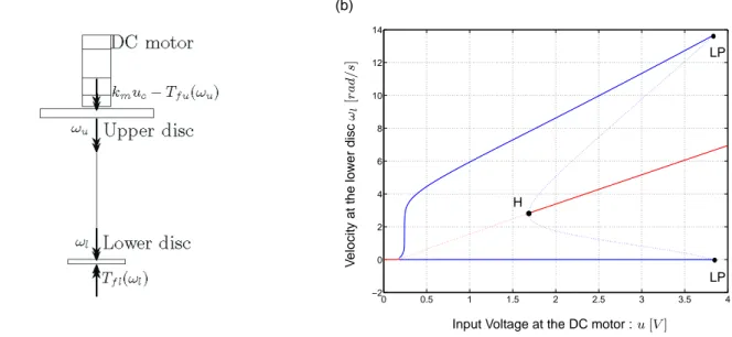
A model of the system is depicted in figure 7(a) and its dynamics characterized by the bifurcation diagram illustrated in figure 7(b). The equations of motions and related parameter values are available in[16]. For a given input voltage at the DC motor, the velocity at the lower disc presents an equilibrium point or/and a LCO. Therefore both solutions are represented through the equilibrium or the maximum and minimum value ofωl, respectively. Note the presence of black dots traducing the occurrence of fold (LP) and hopf (H) bifurcation points.
0 0.5 1 1.5 2 2.5 3 3.5 4 −2 0 2 4 6 8 10 12 14
Input Voltage at the DC motor :u [V ]
V e lo c it y a t th e lo w e r d is c ωl [r a d / s] (a) (b) LP LP H
Figure 7: (a) Model of the drill-string system / (b) Bifurcation diagram : blue and red colors correspond to periodic and equilibrium solutions, respectively; solid and dotted line correspond to stable and unstable solutions, respectively.
4.2 Coupling of an NES to the Primary Structure
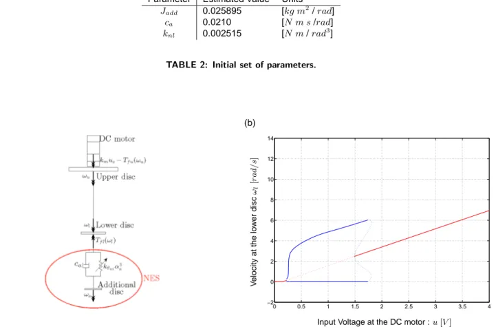
Because of the nonlinear character of the drill-string system, it is meaningful to consider a NES for vibration mitigation of this system (figure 8(a)). Based on a parametric study[16], a set of NES parameters (Table 2) has been worked out. The dynamics related to the controlled system is fully characterized by the bifurcation diagram in figure 8(b).
Parameter Estimated Value Units
Jadd 0.025895 [kg m2/rad]
ca 0.0210 [N m s/rad]
knl 0.002515 [N m/rad3]
TABLE 2: Initial set of parameters.
0 0.5 1 1.5 2 2.5 3 3.5 4 −2 0 2 4 6 8 10 12 14
Input Voltage at the DC motor :u [V ]
V e lo c it y a t th e lo w e r d is c ωl [r a d / s] (a) (b)
Figure 8: (a) Model of the drill-string system coupled to a NES / (b) Bifurcation diagram : blue and red colors correspond to periodic and equilibrium solutions, respectively; solid and dotted line correspond to stable and unstable solutions,
respectively.
Clearly, the new dynamics created presents a drastic improvement as the range of input voltages leading to local and global equilibrium solutions has been increased whereas a significative LCO amplitude reduction is observed on the remaining range.
4.3 Bifurcation Analysis
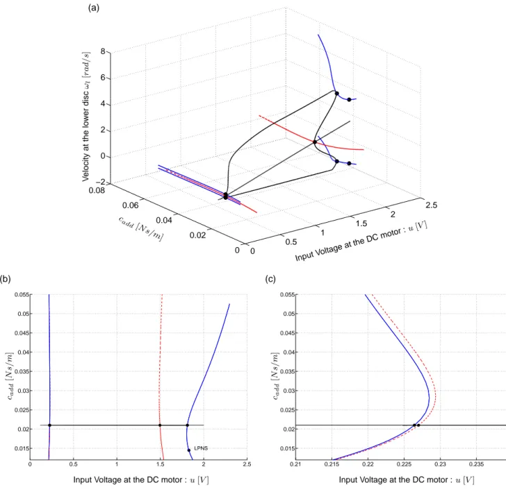
The analysis of the bifurcation points is performed herein. To this end the command line version of MATCONT is used and not MATCONT for maps as the forcing parameter is not harmonic anymore. The aim lies in assessing the quality of the NES parameter values, parametrically chosen. In particular the focus is set upon the damping coefficient value. The results are depicted in figures 9(a-c). Two different objectives can be followed :
1. an increase of the input voltage range leading of the global equilibrium solutions 2. a decrease of the input voltage range leading to unstable equilibrium solutions
The first case tends to be fullfilled when the LP curves get closer from each other whereas for the second case the same property has to be verified for the Hopf curves. The location of the black trace (bifurcation diagram figure 8) is very close from the configurations leading to both the largest range of global equilibrium (cadd=0.018 N s/m) and the smallest range of unstable equilibrium (cadd=0.03 N s/m). A LPNS bifurcation exhibits the presence of Neimarck-Sacker bifurcation point in its surrounding region. 0 0.5 1 1.5 2 2.5 0 0.02 0.04 0.06 0.08 −2 0 2 4 6 8 Input Vol tageat th e DCmoto r :u [V] cadd [Ns/m] V e lo c it y a t th e lo w e r d is c ωl [r a d / s] (a) 0 0.5 1 1.5 2 2.5 0.015 0.02 0.025 0.03 0.035 0.04 0.045 0.05 0.055
Input Voltage at the DC motor :u [V ] ca dd [N s/ m ] 0.21 0.215 0.22 0.225 0.23 0.235 0.24 0.015 0.02 0.025 0.03 0.035 0.04 0.045 0.05 0.055
Input Voltage at the DC motor :u [V ] ca dd [N s/ m ] (b) (c) LPNS
Figure 9: (a) 3D representation of the bifurcation points continuation / (b) Projection in the plane (cadd,u) / (c) Close-up
on the low voltage range. The blue solid line, the red dashed line and the black line correspond to the LP continuation, the Hopf continuation and the bifurcation diagram computed depicted in figure 8, respectively.
Finally, these developments confirm the quality of the parameters parametricaly computed. However some complementary analyses have to be performed for lower damping value where more complex dynamics seem to take place.
5 CONCLUSIONS
This paper presents the development of a new NES design methodology based on bifurcation analysis. In particular, a nonlinear 2DOF composed of a LO coupled to a NES is considered to validate the concept that is applied further on to the design of a nonlinear absorber introduced onto a drill-string system.
Considering a given objective function, this method highlights great benefits from a computational cost viewpoint. It directly takes advantage of the relevant information available in the bifurcation diagrams, namely, the bifurcation points.
Moreover, unlike asymptotical methods, it is characterized by the independence with respect to any simplifications or restrictive assumptions on the system structure or boundary conditions.
This method relies on the use of reliable continuation softwares such as MATCONT which is used herein.
Complementary developments have to be undertaken in subsequent studies to take the codimension 2 bifurcations (LPNS, R1, ...) into account in the design procedure.
Acknowledgments
The authors R. Viguié would like to acknowledge the Belgian National Fund for Scientific Research (FRIA fellowships) for its financial support.
REFERENCES
[1] Frahm, H., A Device for Damping Vibrations of Bodies, US Patent 989958, 1911. [2] Den Hartog, J. P., Mechanical Vibrations, Dover Books on Engineering, 4th edn., 1985.
[3] Gendelman, O. V., Transition of energy to a nonlinear localized mode in a highly asymmetric system of two oscillators, Nonlinear dynamics, Vol. 25, pp. 237–253, 2001.
[4] Gendelman, O. V., Manevitch, L. I., Vakakis, A. F. and McCloskey, R., Energy pumping in nonlinear mechanical
oscilla-tors: Part I - Dynamics of the underlying Hamiltonian systems, Journal of Applied Mechanics, Vol. 68, pp. 34–41, January
2001.
[5] Vakakis, A. F. and Gendelman, O. V., Energy pumping in nonlinear mechanical oscillators: Part II - Resonance capture, Journal of Sound and Vibration, Vol. 68, pp. 42–48, January 2001.
[6] Vakakis, A. F., Inducing passive nonlinear energy sinks in vibrating systems, Journal of Vibration and Acoustics, Vol. 123, pp. 324–332, 2001.
[7] Kerschen, G., Vakakis, A. F., Lee, Y. S., McFarland, D. M., Kowtko, J. J. and Bergman, L. A., Energy transfers in a
system of two coupled oscillators with essential nonlinearity: 1:1 resonance manifold and transient bridging orbits, Nonlinear
Dynamics, Vol. 42, pp. 289–303, 2005.
[8] McFarland, D. M., Bergman, L. A. and Vakakis, A. F., Experimental study of nonlinear energy pumping occurring at a
single fast frequency, International Journal of Non-Linear Mechanics, Vol. 40, pp. 891–899, 2005.
[9] Kerschen, G., McFarland, D. M., Kowtko, J. J., Lee, Y. S., Bergman, L. A. and Vakakis, A. F., Experimental
demonstra-tion of transient resonance capture in a system of two coupled oscillators with essential stiffness nonlinearity, Journal of
Sound and Vibration, Vol. 299, No. 4-5, pp. 822–838, February 2007.
[10] Gendelman, O. V., Gorlov, D. V., Manevitch, L. I. and Musienko, A. I., Dynamics of coupled linear and essentially
nonlinear oscillators with substantially different masses, Journal of Sound an Vibration, Vol. 286, pp. 1–19, 2005.
[11] Lee, Y. S., Kerschen, G., Vakakis, A. F., Panagopoulos, P. N., Bergman, L. A. and McFarland, D. M., Complicated
[12] Kerschen, G., Lee, Y. S., Vakakis, A. F., McFarland, D. M. and Bergman, L. A., Irreversible passive energy transfer in
coupled oscillators with essential nonlinearity, SIAM Journal of Applied Mathematics, Vol. 66, No. 2, pp. 648–679, January
2006.
[13] Gourdon, E. and Lamarque, C. H., Nonlinear energy sinks with uncertain parameters, Journal of Computational and Nonlinear Dynamics, Vol. 1, pp. 187–195, 2006.
[14] Cochelin, B., Herzog, P. and Mattei, P. O., Experimental evidence of energy pumping in acoustics, Compte Rendus de Mécanique, Vol. 334, pp. 639–644, 2006.
[15] Lee, Y. S., Kerschen, G., McFarland, D. M., Hill, W. J., Nichkawde, C., Strganac, T. W., Bergman, L. A. and Vakakis, A. F., Suppression of Aeroelastic Instability by Means of Broadband Passive Targeted Energy Transfers, Part I : Theory, AIAA Journal, Vol. 45, 2007.
[16] Viguié, R., Kerschen, G., Golinval, J.-C., McFarland, D. M., Bergman, L. A. and van de Wouw, N., Using passive
nonlinear targeted energy transfer to stabilize drill-string system, Mechanical Systems and Signal Processing, Vol. 23,
pp. 148–169, March 2007.
[17] Viguié, R., Peeters, M., Kerschen, G. and Golinval, J.-C., Energy Transfer and Dissipation in a Duffing Oscillator Coupled
to a Nonlinear Attachment, Journal of Computational and Nonlinear Dynamics (In Review), 2008.
[18] Manevitch, L. I., Gourdon, E. and Lamarque, C. H., Parameters optimization for energy pumping in strongly
nonhomoge-neous 2 dof system, Chaos, Solitons and Fractals, Vol. 31, No. 4, pp. 900–911, February 2007.
[19] Viguié, R. and Kerschen, G., Toward an optimal design procedure of a nonlinear vibration absorber coupled to a Duffing
oscillator, ISMA conference proceeding, Leuven, 2008.
[20] Gendelman, O. V. and Starosvetsky, Y., Quasiperiodic response regimes of linear oscillator coupled to nonlinear energy
sink under periodic forcing, Journal of Applied Mechanics, Vol. 74, No. 2, pp. 325–331, March 2007.
[21] Gendelman, O. V., Starosvetsky, Y. and Feldman, Y., Attractors of harmonically forced linear oscillator with attached
nonlinear energy sink I : description of response regimes, Nonlinear Dynamics, 2006.
[22] Starosvetsky, Y. and Gendelman, O. V., Attractors of harmonically forced linear oscillator with attached nonlinear energy
sink II : Optimization of a nonlinear vibration absorber, Nonlinear Dynamics, Vol. 51, pp. 47–57, January 2007.
[23] Keller, H., Numerical Methods in Bifurcation Problems, SpringerVerlag),.
[24] Doedel, E., Auto, software for continuation and bifurcation problems in ordinary differential equations, 2007.
[25] Seydel, R., Practical Bifurcation and Stability Analysis. From Equilibrium to Chaos., Springer-Verlag, 2nd edn., 1994. [26] Nayfeh, A. and Balachandran, B., Applied Nonlinear Dynamics. Analytical, Computational, and Experimental Methods,
Wiley-Interscience, Chichester, 1995.
[27] Padmanabhan, C. and Singh, R., Analysis of periodically excited nonlinear-systems by a parametric continuation
tech-nique, Journal of Sound and Vibration, Vol. 184, No. 1, pp. 35–58, 1995.
[28] Sundararajan, P. and Noah, S., An algorithm for response and stability of large order non-linear systems | application to
rotor systems, Journal of Sound and Vibration, Vol. 4, No. 1, pp. 695–723, 1998.
[29] Ribeiro, P., Non-linear forced vibrations of thin/thick beams and plates by the finite element and shooting methods, Com-puters and Structures, Vol. 82, No. 17-19, pp. 1413–1423, 2004.
[30] WGovaerts, Kuznetsov, Y. and Dhooge, A., Numerical continuation of bifurcations of limit cycles in MATLAB, SIAM journal on scientific computing, Vol. 27, No. 1, pp. 231–252, 2005.
[31] Touzé, C. and Amabili, M., Nonlinear normal modes for damped geometrically nonlinear systems: Application to
reduced-order modelling of harmonically forced structures, Journal of Sound and Vibration, Vol. 298, No. 4-5, pp. 958–981, 2006.
[32] Touzé, C., Amabili, M. and Thomas, O., Reduced-order models for large-amplitude vibrations of shells including in-plane
inertia, Proceedings of the EUROMECH Colloquium on Geometrically Nonlinear Vibrations, 2007.
[33] Munoz-Almaraz, F., Freire, E., Galán, J., Doedel, E. and Vanderbauwhede, A., Continuation of periodic orbits in
[34] Doedel, E., Paffenroth, R., Keller, H., Dickmann, D., Vioque, J. G. and Vanderbawhede, A., Computation of periodic
solutions of conservative systems with application to the 3-body problem, International Journal of Bifurcations and Chaos,
2003.
[35] Slater, J., A numerical method for determining nonlinear normal modes, Nonlinear Dynamics, Vol. 10, No. 1, pp. 19–30, 1996.
[36] Dhooge, A., Govaerts, W., Kuznetsov, Y., Mestrom, W., Riet, A. and Sautois, B., MATCONT, University of Gent (Belgium) - University of Utrecht (The Netherlands).