is an open access repository that collects the work of Arts et Métiers Institute of Technology researchers and makes it freely available over the web where possible.
This is an author-deposited version published in: https://sam.ensam.eu
Handle ID: .http://hdl.handle.net/10985/9905
To cite this version :
Christophe LESCALIER, Olivier BOMONT, Anne BOMONT-ARZUR - Machinability in drilling : mechanistic approach and new observer development - In: Eight International Conference on High Speed Machining, France, 2010-12-08 - Proceedings of the Eighth International Conference on High Speed Machining - 2010
MACHINABILITY IN DRILLING
MECHANISTIC APPROACH AND NEW OBSERVER DEVELOPMENT
C. LESCALIER1, O. BOMONT1, A. BOMONT-ARZUR21 - Arts et Métiers ParisTech – 4 rue Augustin Fresnel –57070 Metz France
2 - ArcelorMittal Global Research and Development Gandrange R&D – Long Carbon Bars & Wires BP 3, F- 57360 Amnéville
Abstract: This paper focuses on machinability especially in drilling. It is usually estimated
experimentally based on thrust force and torque measurements, chip morphology analysis, surface quality and tool wear tests. A specific experimental procedure has been developed and tested for many steel grades. However wear tests are probably the most critical point. Wear tests are essential for an industrial application since they lead to know the cost per hole nevertheless they are highly time and work material consuming. Wear pattern and wear rate depend on the thermo mechanical stresses exerted on the cutting tool in the contact zones. A mechanistic approach enables to estimate the mechanical stress distribution along the drill lip. A new observer based on the mechanical thrust and force measurements is proposed to estimate stress distribution dissymmetry and rapidly rank the machinability in drilling. His relevancy is checked for several steel grades and drilling conditions: metallurgical structure and hardness are different, cutting material and coating and cutting conditions vary. Experiments are performed without lubricant.
Keywords: construction steel, machinability, drilling
1 INTRODUCTION
Intensive weight savings and out-sizing programs have been developed in automotive industry leading to increase the mechanical properties of the bulk material of the automotive parts. ArcelorMittal has developed many such specific steel grades designed to be forged even heat treated and machined. Formability and machinability have been systematically investigated including for some Super High Strength Steels which are designed for both high ductility and toughness and fatigue resistance [Bomont et al., 2008].
Our previous studies focused on machinability evaluation in both cutting operations such as turning or drilling. The machinability evaluation protocole developped is based on a standardized experimental method known as Couple Tool Material [Afnor, 2000]. Experiments are to be performed for each association workpiece / cutting tool / machining operation. The result is an operating range, the whole acceptable machining conditions for that association. A machining condition is regarded as acceptable when:
• specific energy values are acceptable,
• chips are regular and fragmented,
• tool wear is regular and controllable,
• surface quality are compatible with common technical requirements.
A solid drilling operation is seemingly simple : a basic kinematics, an operating range expressed using only two coordinates i.e. cutting speed Vc and feed f ... However drilling is a complex operation : the cutting edge is composed of a chisel edge and a cutting lip, the cutting speed as well as the effective cutting geometry vary all along the cutting edge, chips evacuation is rather difficult especially when drilling under dry conditions and so leading to drilling forces enhancement or clogging, wear patterns are numerous and depend on the
Machinability investigations only based on the mean drilling torque and thrust force values are certainly pretty limited. A mechanistic approach would provide relevant information about the local contribution of the cutting edges enabling to sort the machinability of the different steel grades. These approaches are based on a discretization of the cutting edge [Altintas, 2002]. One of the easiest ways to determine the local contribution of the different cutting edges consists in examining the tool engagement [Gong et al., 2005].
2 EXPERIMENTAL DEVICE
The operation investigated is a solid drilling operation. The hole’s depth is about three times the drill diameter. Two different tools are used:
• a Titex A1211 solid HSS drill. The cutting tool diameter is 6 mm. The cutting tool material is a M2 high speed steel grade. The point angle is 118°.
• a Titex A1164 TiN solid carbide drill. The cutting tool material is a K30 micrograin carbide grade. The drill is provided with a TiN coating for universal applications. The point angle is 140°.
Two different steel grades are investigated: a free cutting steel and a high tensile steel. Rm (MPa) HV30
chemical composition
C Mn S
S1 620 140 90 1300 370
S2 920 280 389 1518 11
Table 1 : Steel grades investigated
Machining experiments are performed using a 3-axis NC milling machine Somab Univer 700 and a workholding device envolving a collet chuck mounted on a 9272 Kistler table used to measure both drilling forces and torque. The experimental curves appearance varies depending on the steel grade machined as well as the cutting conditions. Two typical trends are currently seen.
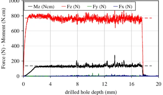
Figure 1 : Force and torque measurements
S1 – A1211 Ø 6 mm– Vc = 22 m/min – f = 0,18 mm/rev
Thrust force Fz and drilling torque Mz increase rapidly when the drill penetrates the workpiece. Thrust force slope is quite higher than the drilling torque one. It is often associated with the drill web. Both drilling torque and thrust force reach a plateau. Tool withdrawal induces a rapid decrease for both the drilling torque and the thrust force. The other force components i.e. Fx and Fy are neglectable especially if the tool is properly ground or reground and its run out is low.
0 200 400 600 800 1000 0 4 8 12 16 20
drilled hole depth (mm)
F o rc e (N ) - M o m en t (N .cm ) Mz (Ncm) Fz (N) Fy (N) Fx (N)
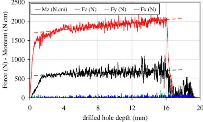
Figure 2 : Force and torque measurements
S2 – A1164 Ø 8 mm – Vc = 70 m/min – f = 0,25 mm/rev
Once more a rapid increase for thrust force occurs as soon as the tool gets in contact with the workpiece while drilling torque rises in a more progressive way. When the cutting edges are fully engaged, both the drilling torque and the thrust force increase almost linearly as far as the tool gets down in the workpiece. The most common assumptions deal with the friction between the tool margins and the chips and the hole walls. The evolution trend may become rather exponential when chip clogging occurs. The withdrawal motion reveals a sudden increase in drilling torque and decrease in thrust force. It is once more generally associated with chip evacuation problems.
The study concerned with machinabiliy in drilling usually assumes that all the cutting conditions being tested lead to a steady state. As a consequence all the experimental curves are supposed to be similar to the curve proposed in Figure 1. The analysis performed on the experimental data collected during the drilling operation also lies on drilling torque and thrust force experimental mean values. Local contributions of the cutting edges are often neglected.
Chip evacuation problems usually are neglected as well as the stress distribution occuring along the cutting edges. It is yet obvious that a difference in stress distributions will induce difference in wear pattern and local wear rate. It is also not relevant to apply roughly machinability testing method when chip evacuation problems occur as seen on the Figure 2.
3 EXPERIMENTAL ANALYSIS
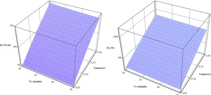
The curves collected for a HSS drill machining S1 or S2 steels belong to the first type (Figure 1). Mean values are calculated. The global trend is shown (Figure 3 and Figure 4). An increase in cutting speed induces a slight decrease of both the drilling torque and the thrust force. However the higher the feed is the higher both drilling torque and thrust force are.
The specific pressure coefficients values i.e. kcMz and kcFz are calculated according to the standard text respectively from the drill diameter Ddrill and the mean values of drilling torque i.e.
Mz and thrust force i.e. Fz. These relations neglect the chisel edge and assume that the cutting force is uniformly distributed along the cutting edge.
2 drill Mz D f Mz 8 kc × × = (1) drill Fz D f Fz kc × = (2)
Once more for both the steel grades machined with a HSS drill, the specific cutting pressures slightly decrease when the cutting speed increase and more clearly decrease when the feed increase. 0 500 1000 1500 2000 2500 0 4 8 12 16 20
drilled hole depth (mm)
F o rce (N ) - M o m e n t (N .cm ) Mz (N.cm) Fz (N) Fy (N) Fx (N)
The experimental values are interpolated using some power models different from the ones proposed in the standard since they assume that the specific cutting pressures also depend on the cutting speed: see Equations (3) and (4).
Mz 2 Mz 1 n ref n ref ref Mz Mz f f Vc Vc kc kc × × = (3) Fz 2 Fz 1 n ref n ref ref Fz Fz f f Vc Vc kc kc × × = (4)
Vcref and fref are reference values which are arbitrarily chosen. The numerical values of the different coefficient are easily determined using a regression analysis which also provides the confidence interval.
Figure 3 : Drilling torque – HSS drill – steel S1 Figure 4 : Thrust force – HSS drill – steel S1
S1 S2 kcMz ref (N/mm²) 1980 ± 130 1530 ± 60 n1 Mz 0.06 ± 0.05 0 ± 0.05 n2 Mz 0.21 ± 0.05 0.20 ± 0.05 kcFz ref (N/mm²) 860 ± 35 1150 ± 70 n1 Fz 0.06 ± 0.03 0.03 ± 0.07 n2 Fz 0.14 ± 0.03 0.24 ± 0.07
Table 2 : Experimental values of the model coefficients
The evolution trend is similar for the drilling torque, the thrust force and both the specific cutting pressures. They mainly depend on feed rather than on cutting speed. This trend agrees with common expectations.
Thrust force is roughly evaluated using the equation of the transient response of a first-order system to a step input: see Equation (1). z is the tool tip depth in the hole being drilled. Two empirical constants should also be precised: the final value Fz0 and the time constant τ. The gain of the Kistler table is supposed to be equal to one: the final value Fz0 should be equal to the mean thrust force value if the experimental curve. The time constant is there expressed as a length. The relation is modified to allow thrust force to increase as long as the drill plunges into the workpiece: see Equation (2). This relation allows a linear evolution of the thrust force which is frequently observed with the carbide drill in the range of cutting conditions tested.
τ − − × =Fz 1 exp z Fz 0 (1) τ − − × × + × = 1 exp z D z a 1 Fz Fz drill 0 (2)
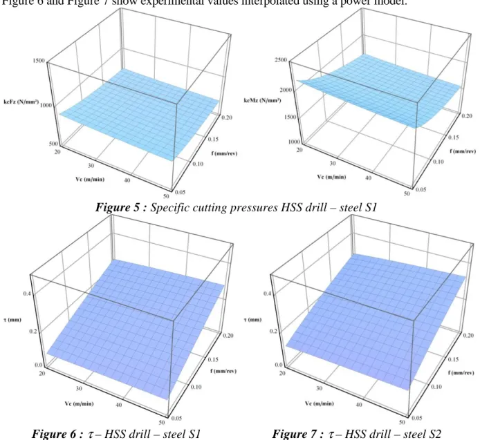
Coefficient of determination values i.e. r² are very close to one. As a consequence the confidence interval ranges are small. The differences between the Fz0 values and the mean thrust forces are neglectable. The “time constant” τ experimental value varies with the steel machined and the cutting conditions and increases with the cutting speed and the feed. It mainly depends on the feed. Even if τ seems to be directly proportional to the feed, the whole cutting conditions which have been tested are considered as relevant according to the standard’s advocacies. Tests prove for instance that τ variations become erratic when feed is too low. Figure 6 and Figure 7 show experimental values interpolated using a power model.
Figure 5 : Specific cutting pressures HSS drill – steel S1
Figure 6 : τ – HSS drill – steel S1 Figure 7 : τ – HSS drill – steel S2
The values of τ are higher for the S2 steel grade whose mechanical performances are quite higher whereas the machinability and especially the chip breaking ability are quite different. The “time constant” τ enables anyway a qualitative analysis of the stress distribution
identical cutting conditions but the thrust force seems better distributed along the cutting edge especially for low feeds where “time constant” is 50% greater than for S1 steel grade.
4 CONCLUSIONS
A standard based machinability analysis is completed with an investigation on thrust force evolution during tool engagement. A basic model may approximate the thrust force evolution even if chips evacuation becomes difficult occuring drilling torque and thrust force enhancement.
The model constants experimental values depend on the material being machined and the drill geometry and the cutting conditions. We focus on a “time constant” τ which indicates the stress distribution is not uniform along the cutting edges. The values of τ depend on the material being machined and the cutting conditions. The evolution of this constant within the cutting conditions range shows that the chisel edge is proportionnally less loaded when the feed or the cutting speed increase. Identical observations have been made about the constant a which may be regarded as an increase rate in thrust force and an observer for some problems such as chip evacuation.
ACKNOWLEDGEMENT
The authors would like to thank Jeremy Bianchin, Daniel Boehm and Lionel Simon and for their assistance in this study. Special thanks to Nicolas Boulanger and Fabrice Reding for their involvement in the experiments and the analysis provided.
REFERENCES
[Bomont-Arzur et al., 2008] Bomont-Arzur, A.; Confente, M. ; Bomont, O. ; Schneider, E. ; Lescalier, C. ; « Super High Strength Steels for automotive industry. Investigation in dry solid carbide drilling operations ». In: 7thInternational Conference on High Speed Machining, 2008. [Afnor, 2000] NF E66-520-7. « Domaine de fonctionnement des outils coupants - Couple outil-matière - Partie 7: application à la technologie de perçage dans le plein » ; November 2000. [Altintas, 2002] Altintas, Y. ; « Manufacturing automation – Metal cutting mechanics, machine-tool vibrations and CNC design » ; Cambridge University Press ; 2002.
[Gong et al., 2005] Gong, Y. ; Lin, C. ; Ehmann, K.F. ; « Dynamics of initial penetration in drilling » ; Journal of Manufacturing Science and Engineering ; 127:280-297 ; 2005.
Information about authors
E-mail address: [email protected]
Tel.: +33-3-87 37 54 35 ; fax: +33-3-87 37 54 70
E-mail address: [email protected] Tel.: +33-3-87 37 54 35 ; fax: +33-3-87 37 54 70
E-mail address: [email protected] Tel.: +33-3 87 72 45 08 ; fax: +33 3 87 72 45 13