HAL Id: hal-00111635
https://hal.archives-ouvertes.fr/hal-00111635
Submitted on 28 Apr 2018
HAL is a multi-disciplinary open access
archive for the deposit and dissemination of
sci-entific research documents, whether they are
pub-lished or not. The documents may come from
teaching and research institutions in France or
abroad, or from public or private research centers.
L’archive ouverte pluridisciplinaire HAL, est
destinée au dépôt et à la diffusion de documents
scientifiques de niveau recherche, publiés ou non,
émanant des établissements d’enseignement et de
recherche français ou étrangers, des laboratoires
publics ou privés.
Thermal shocks on an electrolytic chromium coating in a
solar furnace
P. Douale, S. Serror, R. M. Pradeilles Duval, J. J. Serra, Eric Felder
To cite this version:
P. Douale, S. Serror, R. M. Pradeilles Duval, J. J. Serra, Eric Felder. Thermal shocks on an
elec-trolytic chromium coating in a solar furnace. Journal de Physique, 1999, 9 (PR3), pp.429-434.
�10.1051/jp4:1999367�. �hal-00111635�
Thermal shocks on an electrolytic chromium coating
in a solar furnace
Ph . Douale, S. Serror, R.M. Pradeilles Duval,
J .J.
Serra* and E. Felder**
Direction des Centres d'Essais (DC£), Centre Technique d'Arcueil (CTA), 16 bis avenue Prieur de la Cote d 'Or, 94114 Arcueil, France
"Groupe Haut Flux Thermique d'Odeillo (GHF), 66125 Odeillo, France
•• Groupe Surfaces & Tribologie, Cemef, URA 1374 du CNRS, ~cote des Mines de Paris, BP. 207, 06904 Sophia-Antipolis, France
Abstract. The electrodeposited chromium coatings are currently used to protect surfaces in many industrial cases, such as rolling-mills, landing gear, jack rod or gun barrels. In the latter case, an important thermal effect is superimposed to the frictional one, bringing to the coating flake off. This paper presents a part of a more extended study of the damages induced in gun tubes. It deals with thermal shock resistance analysis of uncoated and chromium coated steel samples. Its aim is to reproduce and study the main damage types observed at the inner surface of gun tubes by using the DCE solar furnace in Odeillo (France). In a real weapon shooting, the thermal pulse can reach flux levels as high as 50 kW/cm• in an extremely brief time (about I Oms). These tbeJlllal conditions cannot be simulated at the focus of a solar furnace, so we have to determine the couple of parameters (flux level and duration) creating the same damage on the samples.
1. THE CEO SOLAR FURNACE
The 45kW Odeillo solar furnace [1] consists of three main elements:
a/ the heliostat, a swivelling plane reflector whose function is to reflect solar radiation in an horizontal north-south direction,
b/ the concentrator, a l0.75m focal length concave mirror covering a 10*1 0m front area. Its peculiar geometry (spherical facets with a radius of curvature double that of the structure on which they are mounted) confers on the focal zone a quasi-constant (± 5%) energy distribution over 50mm diameter circle.
c/ the solar radiation modulating system, comprising :
• a group of slow moving flux prevention doors and curtains whose positions remain fixed for the duration of a test,
• a fast flux attenuator consisting of twenty shutters moving round their vertical axis and acting like venetian blind.
Figure 1 The Odeillo Solar Furnace
Td
Time(s)
The position of both subsystems is controlled by a computer which real-time monitors the direct solar illumination ; it allows calibrated heat fluxes to be delivered in a given timing sequence. The maximum flux density obtained in the focal zone was about 550 W/cm2
, but the use of a second-stage concentrator
allowed up to 1200 W/cm2 flux on the target. Steel samples were cylinders, 40 mm in diameter and 80
mm in height. One of the plane faces was submitted to the radiant flux, and a water-cooling system, incorporated in the middle of the sample, increased the cooling down speed. Some samples were equipped with intrinsic thermocouples (steel/constantan) set at different depths from the exposed face. A trapezoidal flux shape was used, the raising and falling times being fixed to 0.2 second. <l> represents the flux in W/cm2, N the shocks number, Tp the flux plateau duration, Tm the raising time, Td the falling
time, Tr the time between two shocks (see figure 2).
2. A FIRST NUMERICAL SIMULATION
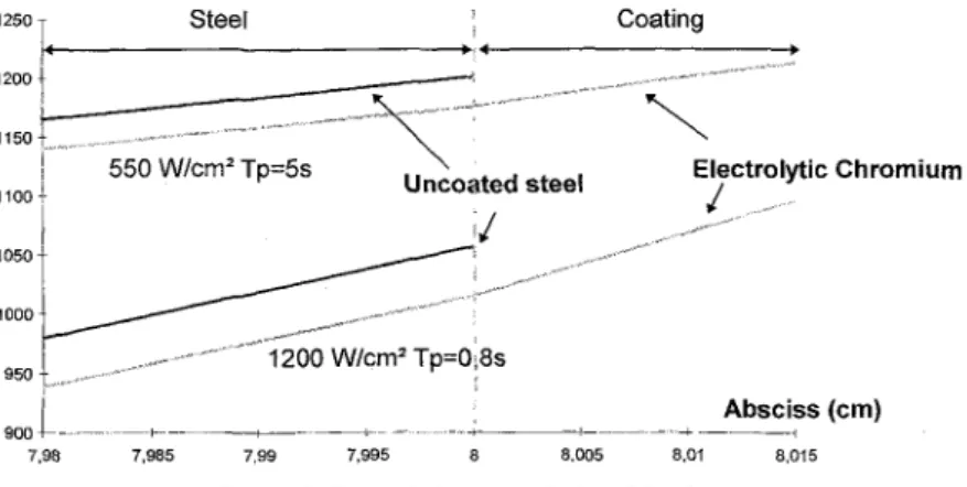
Using a 1-D finite difference scheme (Mur6e), we simulate a thermal shock test on a steel half space, first uncovered and secondly covered by an electrolytic chromium coating. The maximum temperatures on different points in our sample are obtained. During the test, these results are essentially valid along the cylinder axis. This simulation shows us that we must use the second stage concentrator if a high temperature is researched and also if a thermal shock is to be realised. This allows us to avoid too long thermal plateau duration times which may treat the sample.
Temperature (°C)
12so f<---s_t_ee_l _ _ _ _ _ _ _ +----c_o_a_tin_9 _ _ _
1200t _ _ _ ---~;:== ~,,,,,,,, 1150 I I
::)
7,98 550 W/cm 2Tp=5s,.---~,-.::-·
_,.-,.,~lectrolytic
Chromium Uncoated steel /i/
Absciss (cm) 7,985 7,99 7,995 8,005 8,01 8,015Figure 3 Thermal shock simulation (Mur6e)
3. THERMAL SHOCK ON 35NCDV12 STEEL
A preliminary experimental study was performed on uncoated steel samples. Its first aim was to find the flux level and plateau duration required for generating a thermal affected zone (T.A.Z. :the steel zone in which a phase change occurred by hardening, a martensitic structure is obtained) by applying a single thermal shock. Using the previous numerical simulation results and empirical tests results, the following experimental conditions were chosen and the corresponding T.A.Z. measured.
Table 1 Thermal shocks - Experimental conditions on 3SNCDV12 steel
Thermal Flux Tm(s) Td (s) Tp (s) N T.A.Z.
(W/cm2
)
1100 0.2 0.2 0.8 1 200~-tm
1100 0.2 0.2 1.6 1 l.lmm
The temperature field was calculated usmg erther a s1mphfied analytical model, either a preliminary version of 1-D finite difference scheme, either a finite-element thermomechanical code (Abaqus). The measured thermal affected zone depths were also compared to the calculated ones. As it is shown on the following figure, the better correlation between measured and numerical results was obtained when using a temperature dependence of the thermophysical properties : thermal conductivity, specific heat, density. No phase transformation is computed in the code we use.
We choose to compare the area where temperature reaches upto the phase transformation temperature. Obviously this method overestimate the T.A.Z ..
T.A.Z. (mm) 3,5 , - - - 1 OAnalytical model (1) 1!!1 Analytical model (2) OAbaqus (1) ll!IAbaqus (2) •Abaqus (3) Tp = O.Bs Tp = 1.6s
Figure 4 T.A.Z. depths- Comparison experimental results and calculated ones (1) constant properties- (2) temperature dependence of the physical properties
(3) =temperature dependence of the physical properties and absorption on the exposed face fixed to 0.8
4. THERMAL FATIGUE ON AN ELECTROLYTIC CHROMIUM COATING
In a second step the behaviour of electrolytic chromium coatings suffering thermal cycling was investigated. The raising and falling times are still fixed to 0.2 second. The maximum heat flux ljl=l200W/cm2 is used, and Tr is fixed to 30 second such as the surface temperature reached at each shock
would be the same.
In the first hand, using Tp=0.8s and N=I8, we observed the various main damage types similar to those observed on the internal surface of gun tubes : chromium recrystallization, some cracking and steel thermal affected zones. Nevertheless no surface cracking network was obtained.
In a second hand such a surface cracking network was obtained using Tp=0.6s and N=lOOO. Electrolytic chromium deposits [2] elaborated by continuous current (CC) present a columnar growth and a strong <111> fiber texture that slow sharpen during growth. CC deposits have a microcracks net. After a post-deposition thermal treatment, these cracks are a little enlarged (see figure 5). And after a one thousand thermal shocks cycle the chromium surface presents a second cracking network so that its average size is
Figure 5 Electrolytic chromium surface after post-coating thermal treatment
5. TEMPERATURE AND STRESS FIELDS IN COVERED AND UNCOVERED SAMPLES SUFFERING A THERMAL SHOCK
Finally the temperature and stress fields are calculated using the finite-element thermomechanical code Abaqus. As we don't know the steel absorption coefficient we chose to simulate a test which has been experimentally carried out on uncovered steel. Thus the following applied conditions are used : <jl=llOOW/cm2
; Tp=0.8s. Mesh tests are carried out such as we reached the limit under which no changes
affected the results. Three elements are used in the coating depth and the interface contact was supposed to be perfect. As we say it before, the results are closed to the reality when using a temperature dependence of the thermo-mechanical properties. Therefore we first start calculation tests on uncovered steel using this temperature dependence of the properties (case 2) and only by changing the steel absorption coefficient such as we manage to get the nearer T.A.Z. value really observed in the metallurgical analysis. So the steel absorption is fixed to 0.82 but no temperature dependence has ever been used. In case 1, uncovered steel with constant properties was used. Then we started simulation tests on covered steel by a pure chromium 120Jlm coating. Case 3 used constant properties for both materials. Case 4 used temperature dependence except for chromium Young's modulus and Poisson's ratio. And the last case used a steel temperature dependence and constant electrolytic chromium properties [3,4] as they are currently used. The chromium absorption coefficient [5] was fixed to the constant value 0.86, it is mainly available above 600°C.
For the five cases we use a pure elastic behaviour law. Obviously, the maximum temperatures at the surface and the interface (figure 7) are obtained when the thermal plateau duration is finished, i.e. at t=ls. The temperature difference between the one calculated with constant properties and the one with temperature dependence can reach 1 00°C. In fact constant properties makes us really overestimate the temperatures reached and therefore also the T.A.Z .. The same T.A.Z. is obtained when using either uncovered or covered steel. It is true either using temperature dependence or not. We only used constant properties for the electrolytic chromium but the results are approximately closed to the pure chromium using temperature dependence.
920 900 880 860 840 820 800 780 760 740
Tmax (surface)
oc
Tmax (interface)oc
Figure 7 maximum temperatures
0,7 ' "···:····-·"""""""""" " "" i 0,6 0,5 0,4 0,3 0,2 0,1 0 T.A.Z. (mm)
Figure 8 T.A.Z. depths
Figure 9 shows cr,, stresses in uncovered and covered steel samples at the cylinder axis at different depths for each case. When steel is uncovered all stresses are insignificant except crrr. We find a little shearing for covered steel but the main stress is crrr. When the sample is suddenly exposed to the heat flux, the centre goes into compression because of its expansion while the remaining material is still cold and unstrained. This is colloquially known as an « upshock » [6]. For uncovered steel with temperature dependence of the properties the surface material gets less into compression than at a larger depth, due to the steel expansion coefficient in temperature. The stresses time evolution in the steel is similar as it is covered or not, either we compare the constant properties using results (figure 9a and 9c) either the temperature dependence using ones (figure 9b and 9d) but they're less compressive when using temperature dependence.
[x!0 9 ] 0
~\
- -Pa _5 \\
-10 \ (;:j "' -!5 \~
\,
\
"' -2.0 \ -2.5 ----lOmm Smm !mm Surface -3.0 ~-+---;-"S;--.-'.-~:--~-;----,-'n---.7----,.-0 .0 .5 1.5 2.0 2.5 3.0 3.5 4.0 TOTAL TIME [ x1091 ~ -.5 ": "' "' ~ -1.0 f-< CJ) -1.5 .0-
--\
\
'\
\
\
/
>11
.5 1.0 1.5 2.0 2.5 3.0 3.5 4.0 TOTAL TIMEFigure 9b Uncovered steel Figure 9a Uncovered steel
Constant thermal and mechanical properties Temperature dependence of the tbermo-mechanical properties
[x10 9 1
°\\
"~
--5 \ "\
-I 0 \ / \ uo -1 5 I\ I
\~/ "'~
-2.0 CJ) -2.5 -3.0 !Omm 5mm !mm Interface Surface [ xl09] .0 -.4 -.8 -1.2 ": "' "' -1.6 ~ f-< "' -2.0 -2.4 - - - - · " - - ] - - !Omm 5mm !mm Interface Surface .o~-.-Jo5----?L'o-·L'-5-'2"-.o----c2-'.s---__,3."'o--,;3.c,.s~-.-'4.o' .o .5 1.0 1.5 2.0 z.5 3.0 3.5 4.0TOTAL TIME TOTAL TIME
Figure 9c Steel covered by pure chromium Figure 9d Steel covered by pure chromium
Constant thermal and mechanical properties Temperature dependence of the steel thermo-mechanical properties
[xl09]_:
~\
·
-10 \ (;:j \~
:::
\\
-2.5 II
!Omm 5 mm 1 mm Interface Surface -3.0 )<---?----7'o---.7---.-'o---o7---,";;---,7--..-: .0 .5 1.5 2.0 2.5 3.0 3.5 4.0 TOTAL TIMEFigure 9e Steel covered by electrolytic chromium Temperature dependence of the steel thermo-mechanical properties
Stresses in steel covered by electrolytic chromium don't change but chromium stresses are always more compressive than those in steel.
Plastic zones depths were determined with a V on Mises criterion. They' re 30% less important when using temperature dependence. 2,5 2 1,5 0,5 0 Plastic zone (mm) DCase 4 •case 5
Figure 10 Plastic zones depths calculated with a V on Mises cr iteria and an elastic behaviour
6. CONCLUSION
This study shows that calculations results are closer to the reality when temperature dependence of the thermo-mechanical properties with steel covered or not by a chromium coating exposed to such thermal shock conditions is used. In particular it induces some variations to the temperatures, the thermal affected zones, the stresses, and the plastic zones. Some material ·properties in temperature have been measured but all of them aren't known yet. Nevertheless not all of them might be kno\\rn. Therefore we'll start studying the sensibility of each property so that for instance some of the massif properties could be used instead of the « real ones » without too big calculated values changes. We demonstrated that for such an application, dependence in temperature of much properties must be used.
Acknowledgements
The author are grateful to B. Hosdez (CTA/SMS) for his metallurgical analysis and also to J.M. Sayous (CTA/LOT) for the solar furnace tests.
References
[1] Suzanne P., J.J. Serra, «Thermal flux measurement methodology and flux sensors calibration at the ETCA solar fi.1rnace », Proc. 491h CNA TI, Vol.3, pp. 2087-2095 (Perugia I I September 26-30, 1994)
(2] Cassagne V., «Etude de la croissance de dep6ts de chrome electrolytiques - Consequences sur la structure et l'etat mecanique », 1996, These ENSAM
[3] J.L. Coupeau, P. Sabourin, «Etude du comportement de differents materiaux protecteurs avec le Iogiciel de simulation de contraintes thermomecaniques
a
I'interieur des tubes d'armes », rapport OIAT industries 58547, September 1992(4] S. Serror, « Synthese des connaissances sur l' usure des tubes de canon - Proprietes du chrome electrolytique et mode de degradation», Rapport ETCA, December 1996
[5] Incropera F.P., DeWitt D.P., «Fundamentals of Heat and Mass Transfer», Wiley fourth edition, 1996 [6] R.P. Skelton, « Introduction to thermal shock», High Temperature Technology, Vol 8 No 2 (May