HAL Id: hal-01121754
https://hal.archives-ouvertes.fr/hal-01121754
Submitted on 25 Feb 2021
HAL is a multi-disciplinary open access
archive for the deposit and dissemination of
sci-entific research documents, whether they are
pub-lished or not. The documents may come from
teaching and research institutions in France or
abroad, or from public or private research centers.
L’archive ouverte pluridisciplinaire HAL, est
destinée au dépôt et à la diffusion de documents
scientifiques de niveau recherche, publiés ou non,
émanant des établissements d’enseignement et de
recherche français ou étrangers, des laboratoires
publics ou privés.
for Multistandard and Multimode Turbo Decoding
Vianney Lapotre, Purushotham Murugappa Velayuthan, Guy Gogniat, Amer
Baghdadi, Michael Hübner, Jean-Philippe Diguet
To cite this version:
Vianney Lapotre, Purushotham Murugappa Velayuthan, Guy Gogniat, Amer Baghdadi, Michael
Hüb-ner, et al.. A Dynamically Reconfigurable Multi-ASIP Architecture for Multistandard and Multimode
Turbo Decoding. IEEE Transactions on Very Large Scale Integration (VLSI) Systems, IEEE, 2016,
24 (1), pp.383 - 387. �10.1109/TVLSI.2015.2396941�. �hal-01121754�
A dynamically reconfigurable multi-ASIP architecture for multi-standard and multi-mode turbo decoding Vianney Lapotre, Purushotham Murugappa, Guy Gogniat, Amer
Baghdadi, Michael H¨ubner and Jean-Philippe Diguet
Abstract—The multiplication of wireless communication standards is introducing the need of flexible and reconfigurable multi-standard baseband receivers. In this context, multiprocessor turbo decoders have been recently developed in order to support the increasing flexibility and throughput requirements of emerging applications. However these solutions do not sufficiently address reconfiguration performance issues, which can be a limiting factor in the future. This work presents the design of a reconfigurable multiprocessor architecture for turbo decoding achieving very fast reconfiguration without compromising the decoding performances.
Keywords-Wireless communication, turbo codes, ASIP, Dynamic con-figuration.
I. INTRODUCTION
A channel coding technique is typically associated to a variety of parameters and configuration options (frame size, communication channel, signal-to-noise ratio, etc). Among channel coding tech-niques, turbo codes are frequently adopted in the recent wireless standards to reach a very low bit error rate (BER). Furthermore, the high throughput requirement of emerging services imposes the efficient exploitation of different parallelism levels of the underlying algorithms such as sub-block parallelism [1] or shuffled decoding [2] techniques.
The introduction of contention-free interleavers in recent communi-cation standards, such as WiMAX and LTE, enables high-throughput implementations presented in [3]–[8]. These architectures propose to use multiple Soft-Input Soft-Output (SISO) decoders to reach the high throughput requirement of emerging and future standards. These turbo decoders offer certain degrees of flexibility to adapt for instance the number of SISO decoders, the turbo code mode, i.e. Single Binary turbo Code (SBTC) or Double Binary turbo Code (DBTC), or the frame size. However, these efforts do not present any configuration infrastructures associated to these architectures in order to support fast and efficient dynamic configuration switches. Recently, Application Specific Instruction-set Processor (ASIP) solutions have been investigated in order to offer architectures providing good trade-offs in terms of flexibility, throughput and power dissipation. In [9], a flexible and high performance ASIP model for turbo decoding was proposed, which can be configured to support all single and double binary turbo codes up to eight states. The architecture uses shuffled decoding with frame sub-blocking. Afterwards, optimizations on the proposed ASIP, called DecASIP, have been added in [10]. In [11], the authors introduce the FlexiTreP ASIP in a multi-ASIP architecture for turbo decoding to reach the 150 Mbps throughput requirement of LTE. The FlexiTreP ASIP supports both SBTC and DBTC for various standards and it is configured through an interleaver memory, a program memory and the Dynamically Reconfigurable Channel Code Control. In [12], the authors propose a reconfigurable mul-tiprocessor approach in order to decode multiple data streams in parallel. However, the configuration process of the platform is not described. A mixed XML/SystemC simulation model of the platform has been implemented to reach a maximum throughput
V. Lapotrre, G. Gogniat and J.-P. Diguet are with Univ. Bretagne Sud, UMR6285, Lab-STICC, France. e-mail: [email protected]
P. Murugappa and A. Baghdadi are with Telecom Bretagne, UMR6285, Lab-STICC, France. e-mail: [email protected]
M. H¨ubner is with Rurh-Universit¨at, ESIT, Germany. e-mail: [email protected]
Manuscript received MonthX XX, 2013; revised MonthX XX, 20XX.
of 86Mbps, which does not satisfy the throughput requirement of recent communication standards. Furthermore, the latency aspect and the scalability of the configuration process for a higher number of processing elements are not discussed. In fact, previous works provide an efficient way to reach the high performance require-ment of emerging standards. However, the dynamic reconfiguration aspect of these platforms is superficially addressed. Among the few works which consider this issue, we can cite the recent architecture presented in [13], where solutions for the reconfiguration manage-ment of the Network-on-Chip (NoC) based multiprocessor turbo/low-density parity-check (LDPC) decoder architecture presented in [14] were proposed. Up to 35 processing elements (PEs) and up to 8 configuration buses have been implemented. However, the proposed solution does not guarantee that the configuration process can be masked by the current decoding task. Then, stopping the current processing to configure the new configuration is unavoidable and leads to a decoding quality loss in terms of BER. To leverage these issues, this paper presents a novel dynamically reconfigurable turbo decoder providing an efficient and high speed configuration process. The rest of this paper is organized as follows. Section II gives more insights about the motivation of this work. Section III introduces the considered multi-ASIP architecture implementing the RDecASIP processor. Section IV presents the flexibility features added to the initial architecture. Section V presents the implementation results. Finally, section VI concludes the paper.
II. MOTIVATION
When a turbo decoder is designed to support several communi-cation standards, the decoder behavior has to be adapted in order to respect the application requirements and to take into account the communication channel quality. In future systems, simultaneous ap-plications dealing with multiple communication standards have to be considered. In this scenario, the turbo decoder deals with input frames that have to be decoded for multiple applications that use different communication standards or modes. Each application is associated with specific throughput and BER objectives. Moreover, considering a mobile terminal, the configuration associated to an application has to be adapted temporally depending on the communication channel quality evolution. Consequently, each frame received by the turbo decoder is associated to a specific configuration, which takes into account the application requirements and the channel quality. In order to avoid extra delays between two frames associated with different configurations, the configuration process for a frame (i.e. computing and loading the new configuration) can be performed during the processing of the current frame. Thus, the Maximum Configuration Latency (MCL) for a frame k ensuring a null extra delay between two frames is evaluated using Equation (1).
M CL(k) = NP revF rame(k).
F rameSize(k − 1).Rc(k − 1)
T hroughput(k − 1) (1)
where k is the kth received frame, NP revF rame(k) is the number
of consecutive frames decoded with the same configuration that
precedes the frame k, F rameSize(k − 1) is the (k − 1)th frame
size in bits, T hroughput(k − 1) is the throughput requirement
associated with the (k − 1)th data frame and Rc(k − 1) is the
code rate associated with (k − 1)thdata frame. MCL, FrameSize and
Throughput are expressed in seconds, bits and bits/s respectively.
The maximum configuration latency critically decreases with high throughput targeted by emerging and future wireless communication standards. It will reach latencies around few microseconds in LTE-advanced standard that can provide a throughput higher than 1Gbps. Thus, emerging and future high throughput mode and multi-standard architectures will have to deal with maximum configuration
latencies around few microseconds. That is why, in order to face this challenge, this paper brings contributions providing an efficient and high speed dynamic configuration of a multi-mode and multi-standard turbo decoder.
III. UDEC ARCHITECTURE
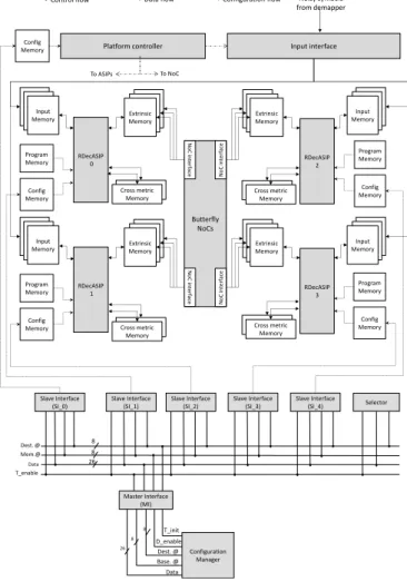
The proposed dynamic reconfigurable UDec turbo decoder archi-tecture is shown in Fig. 1. It consists of two rows of RDecASIPs [15] interconnected via two butterfly topology NoCs. Each row corresponds to a component decoder. In the example of Fig. 1, four ASIPs are organized in 2 component decoders respectively built with 2 ASIPs. Within each component decoder the ASIPs are connected by two 44-bit buses for boundary state metrics exchange (not shown in Fig. 1). The RDecASIP implements the Max-Log MAP algorithm [16]. It supports both single and double binary convolutional turbo codes. Moreover, sliding window technique [17], [18] is used. Large frames are processed by dividing the frame into N windows each with a maximum size of 64 symbols. Each ASIP can manage a maximum of 12 windows. Each ASIP can be configured through a 26x12 configuration memory. The configuration memory contains all parameters required to perform the initialization of the ASIP. Since the RDecASIP is designed to work in a multi-ASIP architecture as described in [10], it requires several parameters to deal with a subblock of the data frame and several parameters to configure the ASIP mode. Concerning the subblock partitioning, each ASIP is configured with the size and the number of windows it has to decode. Furthermore, the last window size can be different so it corresponds to an additional parameter. In a single binary turbo code mode, the address of the tail bits in memory, the size and the number of windows for the tail bits have to be configured. Parameters for the ASIP mode correspond to the location of the ASIP in the architecture, the number of ASIPs required, the parameter which defines if the current ASIP is in charge of tail bits or not, the target standard (3rd Generation Partnership Project - Long Term Evolution (3GPP-LTE), WIMAX, or Digital Video Broadcasting - Return Channel via Satellite (DVB-RCS)) and the scaling factor for extrinsic information. Finally, some seed values are necessary for interleaving address generation in order to exchange information over the NoC that connects the ASIPs of each decoder component. All these parameters are required for a configuration of an ASIP within the platform. The entire configuration load represents 253 bits. Moreover, RDecASIP is associated with 3 memory banks of size 24x256 used to store the input channel Log-Likelihood Ratio (LLR) values. There are also 3 banks of size 30x256 used for extrinsic information storing. Each ASIP is further equipped with two 88x32 memories, which hold 11-bit state metric values and a 16x128 program memory that stores a unified program for turbo decoding modes [15]. To increase the use of parallelism degree, shuffled decoding is used by employing multiple SISO decoders grouped into natural and interleaved domains. Finally, the extrinsic information generated is sent to the other domain through the Butterfly NoC interconnection.
The platform is dynamically configured through a dedicated bus-based communication infrastructure shown in Fig. 1 that consists in a pipeline unidirectional bus implementing incremental burst, multicast and broadcast mechanisms. It can be split in three functional blocks: Master Interface (MI), Slave Interface (SI), and Selector. Each configuration memory is connected to the bus through a SI. The configuration manager deals with the configuration generation which is based on internal decisions and external information and commands. The MI provides an interface allowing the connection of the configuration manager to the bus. The SI provides an interface between the bus and the configuration memory. The Selector provides a simple and efficient solution to select, at run-time, RDecASIPs that
Butterfly NoCs N o C in te rface N o C in te rface N o C in te rface N o C in te rface RDecASIP 0 RDecASIP 2 Extrinsic Memory Program Memory Config Memory Input Memory Cross metric Memory RDecASIP 1 Extrinsic Memory Program Memory Config Memory Input Memory Cross metric Memory Extrinsic Memory Program Memory Config Memory Input Memory Cross metric Memory RDecASIP 3 Extrinsic Memory Program Memory Config Memory Input Memory Cross metric Memory Input interface Noisy symbols from demapper Platform controller To ASIPs To NoC Config Memory
Control flow Data flow Configuration flow
Mem.@ Data T_enable Dest. @ Selector Slave Interface (SI_1) Slave Interface (SI_3) Slave Interface (SI_4) Slave Interface (SI_0) Slave Interface (SI_2) Master Interface (MI) T_init D_enable Data Base. @ Dest. @ Configuration Manager 26 8 8 26 8 8
Fig. 1. Reconfigurable UDec system architecture example with 4 ASIPs
are targeted by the next configuration data. This solution allows the transfer of a data into the configuration memory with a latency of 5 clock cycles. Moreover, thanks to the pipeline nature of the transfers, the configuration infrastructure is able to provide one data per clock cycle to the destination. The rest of the paper focuses on the reconfiguration process of the proposed multi-ASIP architecture through methods which bring more flexibility and more efficiency to the UDec platform. A throughput analysis of the UDec platform considering a stopping-free dynamic reconfiguration can be found in [19].
IV. FLEXIBLEUDEC ARCHITECTURE
This section presents techniques that we propose in order to increase the dynamic configuration ability of the UDec Architecture. In a multi-mode and multi-standard context, the requirements in terms of throughput and BER evolve dynamically. Thus, depending on these requirements, the number of active ASIPs have to be adapted at run-time. Moreover, in order to deal with hot spot and potentially faulty cores management for the UDec architecture, the location of the activated ASIPs has to be dynamically defined. In the initial UDec architecture, the number of ASIPs used for a given configuration is fixed at design time and is equal to the total number of implemented cores. Sections IV-A and IV-B present solutions in order to bring this new flexibility.
A. Ring buses adaptation
The ring buses consist of direct connections between the ASIPs allowing to exchange boundary state metrics. So, when the number
RDecASIP 0 RDecASIP 1 RDecASIP 2 RDecASIP 3 (a) 2 selected ASIPs RDecASIP 0 RDecASIP 1 RDecASIP 2 RDecASIP 3 (b) 3 selected ASIPs RDecASIP 0 RDecASIP 1 RDecASIP 2 RDecASIP 3 4 Selection Vector Selection vector(0) Selection vector(1) Selection vector(2) Selection vector(3)
(c) Flexible architecture illustrated for one ring bus
Fig. 2. Ring buses dynamic adaptation examples and architecture
and the location of the selected ASIPs dynamically evolve, the loop connections between the last and the first selected ASIPs have to be adapted. Fig. 2 shows different examples of the ring buses adaptation when 4 ASIPs are implemented in each component decoder. Fig. 2a shows the case where two ASIPs are selected to perform the decoding task. The location of the first ASIP has been shifted from RDecASIP
0 to RDecASIP 1. Fig. 2b shows the case where three ASIPs are
selected and the location of the first ASIP has been shifted from
RDecASIP 0 to RDecASIP 2. In this case, the last ASIP of the
component decoder is the RDecASIP 0 and the RDecASIP 1 has to be bypassed.
The configuration of the ring buses is done using two parameters. The number of selected ASIPs (NumASIPs) in each component decoder reflecting the level of sub-block parallelism and the shift value (ASIPShift) determining which ASIP is the first selected ASIP. Considering the configuration example presented in Fig. 2a, N umASIP s = 2 and ASIP Shif t = 1 while N umASIP s = 3 and ASIP Shif t = 2 for the example of Fig. 2b. Based on these two parameters, a selection vector is computed. Each bit of this vector corresponds to one RDecASIP of the component decoder. The same
selection vectoris used for the two component decoders of the
plat-form creating a symmetry. The selection vector drives multiplexers that determine the ring buses configuration as shown in Fig. 2c where control signals are presented in dotted lines considering one ring bus for clarity reasons.This proposed Ring buses adaptation requires the implementation of few additional logic gates and multiplexers as illustrated in Fig. 2c. Very limited area overhead is implied. For the example of Fig. 2c with 4 RDecASIPs in each component decoder, the area overhead related to the two corresponding
Ring buses is 0.00229mm2 in 65nm CMOS technology. This
overhead represents 0.3% of the core area of the 4 RDecASIPs
(4 x 0.187mm2 [15]).
B. Butterfly topology NoCs adaptation
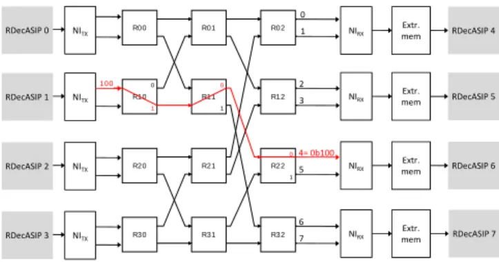
The extrinsic information transfers through the NoC are also im-pacted when the location of the selected ASIPs changes dynamically. Indeed, the routing information for the transfer is computed by the network interface associated with each ASIP depending on a global address of the symbol generated by the ASIP. Fig. 3 illustrates the routing principle for the considered Butterfly topology NoC. This topology allows a unique path in the network between each pair of nodes (source to destination). For each router, there are two inputs and two outputs. A single bit is used in a router to select the appropriate output: 0 for the first output, 1 for the second. In the proposed architecture, the routing information has to be adapted depending on the location of the ASIPs determined by the ASIPShift value
R00 R10 R20 R30 R01 R11 R21 R31 R02 R12 R22 R32 100 0 1 2 3 4 = 0b100 5 6 7 0 1 0 1 0 1 NITX NITX NITX NITX Extr. mem Extr. mem 0 1 2 3 6 7 RDecASIP 4 RDecASIP 5 RDecASIP 6 RDecASIP 7 4= 0b100 5 Extr. mem Extr. mem NIRX NIRX NIRX NIRX RDecASIP 0 RDecASIP 1 RDecASIP 2 RDecASIP 3
Fig. 3. Butterfly topology routing principle
and the level of sub-block parallelism determined by the number of selected RDecASIPs for the configuration in each component decoder (NumASIPs).
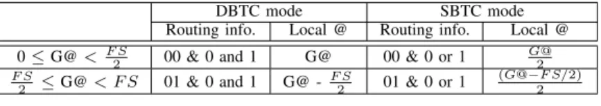
The routing information is generated from a global address (G@) generated by the ASIP. As an example, Table I shows the routing information corresponding to the configurations for 2 selected ASIPs for both SBTC and DBTC modes. In this example the ASIPShift value is equal to 0. When two RDecASIPs are selected in each component decoder, the frame which has to be decoded is split and each RDecASIP is associated with half of the frame. Thus two cases are met as shown in Table I. When the global address generated by the ASIP is lower than the frame size (FS) divided by two, the extrinsic information has to be sent to the first ASIP of the second component decoder while it has to be sent to the second ASIP when G@ is between F S/2 and F S. Considering an architecture configuration implementing eight RDecASIPs, i.e. four in each component decoder, three bits are necessary to route the information through three routers. The last bit of the routing information depends on the turbo code mode. In DBTC mode a message is split, so one half is sent with the last stage route to 0 and the other half with the last stage route to 1. That is why the routing information is presented in the form ”00 & 0 and 1” in Table I. In SBTC mode, the route of the last stage is determined by the LSB of the global address. That is why the routing information is presented in the form ”00 & 0 or 1” in Table I. If the global address is odd, the route of the last stage is 1 while it is 0 when the global address is even.
The extrinsic information has to be stored in the extrinsic memory associated with each RDecASIP. Thus a local address (Local @) is computed depending on the global address computed by the emitter RDecASIP and the level of sub-block parallelism as shown in Table I. In DBTC mode, one complete extrinsic information for one symbol is stored in each memory address. Thus depending on the level of sub-block parallelism, the extrinsic information is spread over the extrinsic memories of each RDecASIP from the local address 0 to N umASIP sF S where N umASIP s is the number of the selected RDecASIPs in each component decoder. In SBTC mode, extrinsic information for two symbols is stored in each memory address. Thus depending on the level of sub-block parallelism, the extrinsic information is spread over the extrinsic memories of each RDecASIP
from the local address 0 to F S/N umASIP s2 .
When the ASIPShift value differs from 0, the routing information can be computed as shown in Fig. 4. To obtain the final routing information taking into account the ASIPShift value, the initial routing information is first added with 2 × ASIP Shif t (since each router has two output ports) and then, a modulo operator is used in order to ensure a loop-like configuration where RDecASIP 0 and RDecASIP 4 can logically follow the RDecASIP 3 and RDecASIP 7 respectively. These flexible parameters are introduced in the 26-bit width configuration memory associated with the platform controller. It also
DBTC mode SBTC mode Routing info. Local @ Routing info. Local @ 0 ≤ G@ < F S2 00 & 0 and 1 G@ 00 & 0 or 1 G@2
F S 2 ≤ G@ < F S 01 & 0 and 1 G@ -F S 2 01 & 0 or 1 (G@−F S/2) 2 TABLE I
ROUTING INFORMATION FOR A2SELECTEDASIPS CONFIGURATION
RDecASIP G@ Routing information generation Frame Size (FS) NumASIPs + 2 x ASIPShift modulo Final Routing information NITX Number of RDecASIPs implemented in each component decoder
Fig. 4. Complete routing information generator Nb. Transfer latency
ASIPs FPGA1 125MHz ASIC2500MHz
in ns in clock cycles in ns in clock cycles 4 1 032 129 86 43 8 1 320 165 110 55 16 1 896 237 158 79 32 3 048 381 254 127 64 5 352 669 446 223 128 9 960 1245 830 415 TABLE II
ESTIMATEDCONFIGURATION TRANSFER TIME INnsFOR ANASIC
IMPLEMENTATION(1MEASURED-2ESTIMATED)
contains some parameters which are used to spread the input symbols over the input memories of each activated ASIP. Considering all con-figuration memories of the platform, a concon-figuration represents 286 bits per activated ASIP plus 182 bits for the platform configuration memory.
V. IMPLEMENTATION RESULTS
In order to evaluate the configuration latency of the proposed archi-tecture, a hardware prototype of the configuration infrastructure has been developed on a Xilinx XUPV5 platform implementing a Virtex 5 LX110T field-Programmable Gate Array (FPGA). Configuration latencies were evaluated for several numbers of RDecASIPs. For this purpose, a MicroBlaze processor connected to the configuration infrastructure through a Xilinx Fast Simplex Link (FSL) is used to generate and transfer the configuration information and the design frequency is set to 125 MHz. Table II shows the configuration transfer latencies in nanoseconds and in number of clock cycles for different numbers of RDecASIPs being reconfigured. More-over, estimations for an 1pplication-Specific Integrated Circuit (ASIC) implementation targeting 65nm CMOS technology at 500 MHz are provided. The maximum speedup of 12 is reached thanks to a higher clock frequency and by removing the FSL link between the processor and the configuration infrastructure. Results show that up to 128 RDecASIP can be configured in 9960ns and 830ns for FPGA and ASIC implementation respectively.
In the recent related work proposed in [13], where the configuration infrastructure consists of several buses each connected to a group of 4 PEs, up to 8 buses have been implemented to configure 35 PEs. However, the way the buses are driven is not described in details in [13] but the management of the 8 buses in parallel should increase the complexity of the configuration manager used to load new configu-rations. Results of Table III compare the proposed solution with both initial work and the work presented in [13] where the clock frequency
Initial Proposed solution [13] UDec FPGA ASIC ASIC
[10] (65nm) (90nm) Supported TC3 TC3 TC3 codes LDPC LDPC Configuration not bus-based bus-based infrastructure available bus - 125 MHz 500 MHz 200 MHz frequency Number of - 1 8 buses Number of - 128 35 PEs Max. config. - 9 960 ns1 830 ns2 44 275 ns2 latency TABLE III
CONFIGURATION ARCHITECTURE AND LATENCY COMPARISON
(1MEASURED-2ESTIMATED-3TC=TURBO CODES)
of each bus is set to 200 MHz. Moreover, in order to estimate the maximum configuration latency of the architecture presented in [13], we assume that a one clock cycle latency is necessary for each configuration data that has to be transfered. Moreover, the maximum configuration latency is computed considering the maximum number of PEs and the maximum configuration load per PE (i.e. 1771 memory lines in [13]). The high maximum configuration load per PE of [13] comes from the necessity to load interleaving tables in each PE while this information is generated at run-time in the RDecASIP processor. Compared with [13], the proposed solution guarantees configuration latency below 10µs and 1µs in FPGA and ASIC implementation respectively while 44µs are necessary to configure 35 PEs in the ASIC implementation presented in [13] using a multi-buses approach.
Both works presented in [10] and [13] support TC and LDPC (Low-Density Parity-Check) codes. In LDPC mode, data exchange can be performed through a global ring bus that connects all the ASIPs of the platform as presented in [10]. It is worth noting that methods proposed in this paper are fully compatible with the integration of LDPC mode. In particular, the ring buses adaptation method presented in Subsection IV-A can be adapted for LDPC mode by adding a link between both groups of ASIPs of the two component decoders in order to provide a global ring bus. At the processor level, the configuration and program memories can be organized in order to take advantage of broadcast mechanism provided by the configuration infrastructure since the major part of configuration parameters for LDPC mode is identical for all selected ASIPs. Indeed, the main configuration parameters for LDPC mode concern the parity check matrix configuration and content, which are identical for all ASIPs.
VI. CONCLUSION
The multiplication of communication standards leads to complex scenarios where the configuration process becomes a key point in order to guarantee high performances. In this context, this work tackles the dynamic configuration issues of multiprocessor platform
for turbo decoding in order to respect hard constraints imposed by emerging multi-mode and multi-standard scenario. The configuration process of the entire platform implementing 128 RDecASIPs can be performed in less than 10µs with FPGA implementation. Moreover, ASIC synthesis results considering up to 128 RDecASIPs have demonstrated that a configuration transfer latency below 1µs is reachable providing an efficient solution in order to support dynamic configuration in the multi-mode and multi-standard scenario.
REFERENCES
[1] O. Muller, A. Baghdadi, and M. Jezequel, “Parallelism efficiency in convolutional turbo decoding,” EURASIP Journal on Advances in Signal Processing, pp. 927–920, 2010.
[2] J. Zhang and M. Fossorier, “Shuffled iterative decoding,” IEEE Trans-actions on Communications, vol. 53, no. 2, pp. 209–213, 2005. [3] C.-C. Wong and H.-C. Chang, “Reconfigurable turbo decoder with
parallel architecture for 3GPP LTE system,” IEEE Transactions on Circuits and Systems II: Express Briefs, vol. 57, no. 7, pp. 566–570, 2010.
[4] C.-H. Lin, C.-Y. Chen, E.-J. Chang, and A.-Y. Wu, “Reconfigurable parallel turbo decoder design for multiple high-mobility 4g systems,” Journal of Signal Processing Systems, vol. 73, no. 2, pp. 109–122, 2013. [5] Y. Sun and J. Cavallaro, “A flexible ldpc/turbo decoder architecture,” Journal of Signal Processing Systems, vol. 64, no. 1, pp. 1–16, 2011. [6] C.-H. Lin, C.-Y. Chen, and A.-Y. Wu, “Area-efficient scalable map
processor design for high-throughput multistandard convolutional turbo decoding,” Very Large Scale Integration (VLSI) Systems, IEEE Transac-tions on, vol. 19, no. 2, pp. 305–318, Feb 2011.
[7] G. Wang, H. Shen, Y. Sun, J. Cavallaro, A. Vosoughi, and Y. Guo, “Parallel interleaver design for a high throughput hspa + /lte multi-standard turbo decoder,” Circuits and Systems I: Regular Papers, IEEE Transactions on, vol. 61, no. 5, pp. 1376–1389, May 2014.
[8] M. May, T. Ilnseher, N. Wehn, and W. Raab, “A 150Mbit/s 3GPP LTE turbo code decoder,” in proc. of the Design, Automation and Test in Europe Conference & Exhibition (DATE), 2010, pp. 1420–1425. [9] O. Muller, A. Baghdadi, and M. Jezequel, “Asip-based multiprocessor
soc design for simple and double binary turbo decoding,” in proc. of the Design, Automation and Test in Europe Conference& Exhibition (DATE), vol. 1, 2006, pp. 1–6.
[10] P. Murugappa, A.-K. R., A. Baghdadi, and M. J´ez´equel, “A flexible high throughput multi-asip architecture for ldpc and turbo decoding,” in Proc. of Design, Automation and Test in Europe Conference & Exhibition (DATE), 2011, pp. 1–6.
[11] C. Brehm, T. Ilnseher, and N. Wehn, “A scalable multi-asip architecture for standard compliant trellis decoding,” in proc. of the International SoC Design Conference (ISOCC), 2011, pp. 349–352.
[12] S. Kunze, E. Matus, G. Fettweis, and T. Kobori, “A ”multi-user” approach towards a channel decoder for convolutional, turbo and ldpc codes,” in Proc. of the IEEE Workshop on Signal Processing Systems (SIPS), Oct 2010, pp. 386–391.
[13] C. Condo, M. Martina, and G. Masera, “Vlsi implementation of a multi-mode turbo/ldpc decoder architecture,” IEEE Transactions on Circuits and Systems I: Regular Papers, vol. 60, no. 6, pp. 1441–1454, June 2013.
[14] ——, “A network-on-chip-based turbo/ldpc decoder architecture,” in Proc. of the Design, Automation and Test in Europe Conference & Exhibition (DATE), 2012, pp. 1525–1530.
[15] V. Lapotre, P. Murugappa, G. Gogniat, A. Baghdadi, J.-P. Diguet, J.-N. Bazin, and M. Huebner, “Optimizations for an Efficient Reconfiguration of an ASIP-Based Turbo Decoder,” in Proc. of the IEEE International Symposium on Circuits and Systems (ISCAS), 2013.
[16] P. Robertson, E. Villebrun, and P. Hoeher, “A comparison of optimal and sub-optimal map decoding algorithms operating in the log domain,” in proc. of the IEEE International Conference on Communications (ICC), vol. 2, 1995, pp. 1009–1013.
[17] C. Schurgers, F. Catthoor, and M. Engels, “Memory optimization of map turbo decoder algorithms,” IEEE Transactions on Very Large Scale Integration (VLSI) System, vol. 9, no. 2, pp. 305–312, 2001.
[18] N. Benedetto, D. Divsalar, G. Montorsi, and F. Pollara, “Soft-output decoding algorithms in iterative decoding of turbo codes,” tech. rep., JPL TDA Progress report, 1996.
[19] V. Lapotre, P. Murugappa, G. Gogniat, A. Baghdadi, M. Hubner, and J.-P. Diguet, “Stopping-free dynamic configuration of a multi-asip turbo decoder,” in Digital System Design (DSD), 2013 Euromicro Conference on. IEEE, 2013, pp. 155–162.