HAL Id: hal-02402427
https://hal.sorbonne-universite.fr/hal-02402427
Submitted on 10 Dec 2019
HAL is a multi-disciplinary open access
archive for the deposit and dissemination of
sci-entific research documents, whether they are
pub-lished or not. The documents may come from
teaching and research institutions in France or
abroad, or from public or private research centers.
L’archive ouverte pluridisciplinaire HAL, est
destinée au dépôt et à la diffusion de documents
scientifiques de niveau recherche, publiés ou non,
émanant des établissements d’enseignement et de
recherche français ou étrangers, des laboratoires
publics ou privés.
a Stable DMC-Based Electrolyte for Na-Ion Batteries
Claudio Cometto, Guochun Yan, Sathiya Mariyappan, Jean-marie Tarascon
To cite this version:
Claudio Cometto, Guochun Yan, Sathiya Mariyappan, Jean-marie Tarascon.
Means of Using
Cyclic Voltammetry to Rapidly Design a Stable DMC-Based Electrolyte for Na-Ion Batteries.
Journal of The Electrochemical Society, Electrochemical Society, 2019, 166 (15), pp.3723 - 3730.
�10.1149/2.0721915jes�. �hal-02402427�
Means of Using Cyclic Voltammetry to Rapidly Design a Stable
DMC-Based Electrolyte for Na-Ion Batteries
Claudio Cometto, 1,2Guochun Yan, 1,2Sathiya Mariyappan, 1,2 and Jean-Marie Tarascon 1,2,3,z
1Chimie du Solide-Energie, UMR 8260, Collège de France, 75231 Paris Cedex 05, France
2Réseau sur le Stockage Electrochimique de l’Energie (RS2E), FR CNRS 3459, Amiens 80039, France 3Sorbonne Université, CNRS, 75005 Paris, France
Na-ion batteries are standing as a serious contender to the Li-ion technology for mass storage applications provided we fully master their chemistry, among which the electrolyte is of paramount importance. It controls the degree of parasitic reaction that results in the growth of the solid electrolyte interface (SEI) which governs the battery performances in terms of capacity retention, lifetime, etc… Herein, we show how cyclic voltammetry (CV) can be used to rapidly spot hints of electrolyte decomposition and determine whether the resulting species are either solubilized or adsorbed leading to the SEI formation. Using this approach, we identified a new electrolyte, which consists of a solution of 1M NaPF6in EC-DMC (1:1 v/v ratio) to which we added three additives namely vinylene
carbonate (VC), sodium (oxalate) difluoro borate (NaODFB) and tris (trimethylsilyl) phosphite TMSPi. This novel electrolyte when implemented in today’s practical full Na3V2(PO4)2F3/C Na-ion cells gives the best high temperature performances in terms of
cyclability and self-discharge. Using CV we could rationalize this finding and unambiguously prove that NaODFB is ruling the SEI formation while TMSPi is essential to control its growth and for capturing both O2and acid impurities responsible for deleterious
reactions occurring at relatively high potentials.
© The Author(s) 2019. Published by ECS. This is an open access article distributed under the terms of the Creative Commons Attribution 4.0 License (CC BY,http://creativecommons.org/licenses/by/4.0/), which permits unrestricted reuse of the work in any medium, provided the original work is properly cited. [DOI:10.1149/2.0721915jes]
Manuscript submitted September 3, 2019; revised manuscript received October 22, 2019. Published November 11, 2019.
Rechargeable Lithium-ion batteries are nowadays crucial for the development of portable electronic market and distinguished pro-gresses have been made in terms of stability and safety during last decades.1 However, the continuous depletion of the Li reserves
re-quires a concrete scientific effort aimed at the discovery of new sustain-able energy storage devices, based on the more abundant Na alkali.2
Due to the low cost of this element, Na-ion batteries could potentially become an attractive solution for the large-scale storage of the highly intermittent solar and wind energy. Towards this purpose, researches have been focused to identify suitable electrode and electrolyte ma-terials for Na-ion battery application. Few systems based on sodium layered oxide/Hard carbon (C) and Na3V2(PO4)2F3(NVPF)/C have
already been demonstrated.3 Among them the NVPF / hard carbon
(C) system which is the topic of this paper is the most promising be-cause of both the structural stability and high redox potential of NVPF (∼4V), however some electrolyte fine tuning remains to be done. A stable SEI (solid electrolyte interface) is fundamental to minimize side reactions between electrode and electrolyte, hence to enhance the bat-tery performances.4–6Thus it is of paramount importance to master its
formation which changes with the involved chemistry. For instance, the milder acidity of Na+ as compared to Li+ modifies the nature of the SEI formation together with its increased solubility. Hence, the SEI with Na-ion batteries is relatively less stable than their Li-counterparts7,8and the SEI stability difference is more prominent at
high temperatures.
From our recent studies,9we observed a more pronounced
dissolu-tion of SEI component in presence of linear carbonate solvents such as DMC. More specifically, we demonstrated that the reductive decom-position products shuttle to and poison the positive electrode hence severely deteriorating the electrochemical performance at high tem-peratures. To reduce this deterioration we have designed a new elec-trolyte using solely cyclic carbonate solvents (EC-PC) together with vinylene carbonate (VC), sodium (oxalate) difluoro borate (NaODFB), propane sultone (PS) and succinonitrile (SN) as additives.10NVPF/C
Na-ion cells having high temperature performances could then be re-alized but to the expense of practical issues associated to the high vis-cosity of this DMC-free electrolyte. Bearing in mind that the usage of linear carbonate is quite essential to minimize the electrolyte viscosity and improve its wettability to polyolefinic separator,11we have tried
to replace EC-PC by EC-DMC while maintaining the same additives,
zE-mail:jean-marie.tarascon@college-de-france.fr
but the cell performance was deteriorated. So, we extended our search for new additives that could harmoniously work with DMC as well; that is to protect the NVPF electrode from the decomposition prod-ucts of DMC. Interestingly, tris (trimethylsilyl) phosphite (TMSPi) was demonstrated to protect positive electrode in Li-ion batteries,12,13
hence our decision to explore its use in DMC–based sodium electrolyte to protect NVPF surface. We herein report a new 1M-NaPF6EC-DMC
electrolyte solution containing three additives namely TMSPi, viny-lene carbonate and NaODFB (Chart1) that shows excellent cycling and self-discharge performances at 55°C. The VC and NaODFB were maintained in our new electrolyte formulation because of their feasi-bility to give at the negative electrode a stable polymer matrix and a thin deposit of NaF nanocrystals as experienced in our early work.
As of today, identifying a perfect electrolyte formulation with dif-ferent additives working in synergy is quite complex as we mainly depend on the trial and error approach to choose the additives. Com-putational approaches have so far no success in predicting the synergy between various additives.14In addition, the nature and the
compo-nents of SEI formed are usually studied by both in situ and ex situ analytical techniques (XPS, TOFSIM, etc…) at large instrument facil-ities. Access to large instrument facilities to determine the outcome of electrochemical decomposition products (adsorbed vs solution) form-ing the SEI is time consumform-ing renderform-ing the search for new additives a slow process. Herein, we demonstrate how cyclic voltammetry (CV),
a well-known technique to the battery community, can be used differ-ently as an elegant tool to rapidly provide qualitative and quantitative insights about the thermodynamics and kinetics of the reaction pro-cesses associated to each additive, hence enhancing the confection of new electrolytes. Within the field of batteries, CV has been used as an electrochemical tool for studying liquid electrolytes15–17with the
analysis being mainly restricted to very low scan rates (v in the order of 1 mV/s) and limited attention to the reverse oxidative scan at high potentials. Herein we show how adjusting the CV scan rate is essen-tial to determine whether the species resulting from the reductive bond cleavage of additives are either adsorbed (e.g. forming the SEI) or re-main in solution. Moreover, we even present an experimental protocol to access the degree of stability of the SEI formed with temperature. Overall, the CV technique explored here could be used as a screening test for the electrolyte additives and to identify the optimum combi-nations. A logical way to present our study could consist in showing the CV studies for all the additives we have tried prior reaching the optimum electrolyte formulation. For fear of being too long and loose the essence of the work, we rather decided to first present the battery performances and then show how this practical result can be rapidly confirmed and scientifically rationalized by CV.
Experimental
Electrolyte preparation.—Our electrolytes were prepared by
dis-solving one molar NaPF6 (Stella, Japan) in a mixture of
sol-vents composed of DMC (Sigma Aldrich, >99%, anhydrous, or BASF, USA) and EC (Mitsubishi chemical, Japan), or a pure sol-vent such as PC (BASF, USA), acetonitrile (99.9%, anhydrous, Acros) or diglyme (99.5%, anhydrous, Sigma Aldrich) in the Ar-filled glove box (MBraun MB200B). Lastly, prior to their use, all solvents were dried by adding molecular sieve (4 Å, Sigma) till their water contents become lower than 10 ppm as determined by Karl-Fisher titration (Metrohm 899 coulometer). Vinylene carbon-ate (VC, Sigma), tris(trimethylsilyl) phosphite (TMSPi, TCI) and home-made Sodium (oxalate) difluoro borate (NaODFB, the synthe-sis has been already reported10) were used as additives without further
purification.
Electrochemical measurements of NVPF/C cells.—
Na3V2(PO4)2F3(NVPF, 12.0 mg/cm2) tapes were casted by spreading
the slurries (NVPF materials, polyvinylidene difluoride and carbon black (the weight ratio is 90:4:6) within N-methyl-2-pyrrolidone) onto Al foil. The hard carbon (C, 6.0 mg/cm2) tapes were casted by
spreading the slurries (hard carbon materials, carboxymethyl cellulose and carbon black (the weight ratio is 95:2:3) within deionized water) onto Al foil. All of the electrodes were dried in a Buchi oven under vacuum (lower than 100 mbar) at 80 degree Celsius for 24 h prior to be transferred into glove box. The electrochemical performances of NVPF/C full cells were evaluated in 2032-type coin cells separated by one layer of glass fiber containing 150μL of desired electrolytes. All cells were galvanostatically cycled by using VMP3 or MPG2 potentiostat (Bio-Logic, France) at 55°C or 25°C, and the cycling rates were calculated on the basis of NVPF material (1C= 128 mA g−1).
Cyclic voltammetry measurements.—The working electrode was
a 3 mm diameter glassy carbon (Bio-Logic, France) disk carefully pol-ished by using a suspension of alumina (0.04μ), ultrasonically rinsed in water, rinsed by ethanol and dried before use. The counter electrode was a platinum wire, and a non-aqueous Ag+/Ag reference electrode (silver wire immersed in an acetonitrile/0.1 M tetrabutylammonium perchlorate/0.01 M AgNO3solution) was used for all the CV
experi-ments. The potential values were then referred to the Na+/Na couple (ENa+/Na= −2.77 V vs Ag+/Ag, measured in the studied electrolyte) or to the Li+/Li couple (ELi+/Li= −3.18 V vs Ag+/Ag). CV data were
obtained by using a VMP3 potentiostat (Bio-Logic, France) and all the experiments were carried out in the Ar-filled glove box (MBraun MB200B).
Mass spectrometry analysis of the gas products.—The gases
gen-erated during the formation cycle of a 18650-type cell at 55°C have been recovered in an hermetic coffee bag enclosure and analyzed by using a trace GC ultra gas chromatograph (Thermo Scientific).18The
gas samples were transferred into the split/splitless injector maintained at 200°C. The chromatographic separation was performed on a “HP-PLOT/Q” polystyrene–divinylbenzene-based capillary column (30 m, 0.32 mm i.d., 20 mm) from Agilent J & W Technologies followed by a process using a post-capillary column “Rtx-1” (15 m, 0.25 mm i.d., 0.25 mm, 100% dimethyl polysiloxane) from Restek. The GC was interfaced with an ISQ mass spectrometer (Thermo Scientific). The compound identification was carried out by using the National Insti-tutes of Standards (NIST) library.
Results and Discussion
Battery tests.—Cycling and self-discharge tests of NVPF/C full
cells were performed at 55°C to find a suitable electrolyte for Na-ion batteries. All the experiments were carried out with an experimental protocol that consists in cycling the cell 10 times prior to performing one week self-discharge at 100% state of charge (∼4.3 V) and cycling again at C/10 rate (1C= 128 mA g−1). 1M solution of NaPF6in
EC-DMC (1:1 by volume) solution was taken as a mother electrolyte. The influence of additives on the electrochemical performance was studied separately on each single additive (VC, NaODFB and TMSPi) and then on the mixture of all three additives (3% VC,+ 0.5% NaODFB, + 1% TMSPi). The electrochemical performances were compared by taking into account the capacity retention of the cells (Figure1a), capacity re-tention before and after one week of self-discharge as Q11th-dis/Q11th-cha
(discharge capacity divided by the charge capacity of the 11th cycle) the percentage of recovered capacity as Q12th-dis/Q11th-cha(Figure1b)
and the change in ohmic drop upon cycling (Figures1cand1d). The cumulative performance analyses show that the best electro-chemical performance was obtained with the mixture of three addi-tives (3% VC,+ 0.5% NaODFB, + 1% TMSPi). The single additives namely TMSPi and VC also show better performance with respect to capacity retention and self-discharge recovery capacity in comparison to the mother electrolyte. In contrast, addition of 0.5% NaODFB de-teriorates the capacity retention as compared to the mother electrolyte 1M NaPF6in EC-DMC since only 90% of the capacity was recovered
after self-discharge tests. Interestingly the capacity decay is larger for TMSPi while the recovery is the greatest one (Figure1b). This effect could be due to the easiness of the TMSPi oxidation that favors the reduction of NVPF. This contrasts with the use of NaODFB which acts mainly on reduction as will be confirmed later on.
To reveal the underlying reason of such performance variations of the NVPF/C cells with various electrolytes, the apparent resistance val-ues of NVPF/C cells were retrieved from the voltage-current curves19
and shown in Figures1cand1d. A considerable increase in the ohmic drop was observed for the simple EC/DMC electrolyte over the cy-cle number at 55°C, and an even larger growth was found with the addition of NaODFB that accounts for the drastic capacity decay as observed in Figure 1a. The use of VC or TMSPi sensibly reduces the ohmic drop raise and the best results were achieved by adding all the components (VC, NaODFB and TMSPi). Overall, compared to the single additives, the mixture of additives shows better electrochemical performance (Figure1e), hence showing a synergy between different additives in the SEI creation. To understand this synergetic effect fur-ther, cyclic voltammetry experiments were used and are explained next.
Cyclic voltammetry.—Classical glassy carbon, as previously used
in the battery field,20–22was here selected as carbonaceous working
electrode in order to model the hard carbon anode used in Na-ion batteries. The choice for such an electrode is rooted in its planarity that leads to a significant simplification in terms of experimental pro-cedure and reproducibility, but also in the well mastered theoretical treatment of the current-voltage plot for planar electrodes.23By using
Figure 1. a, the cycling performances of NVPF/C cells with various electrolytes at 55°C. b, the percentage of capacity retention and recovery after the self-discharge measurements of NVPF/C cells at 100% SoC for 1 week. c, the direct current resistance of NVPF/C cells during the 55°C cycling process. A zoom is reported in d. e, the voltage-capacity curve at 10th, 20thand 30thcycle for the mixture of all three additives (3% VC,+ 0.5% NaODFB, + 1% TMSPi).
in the glassy carbon electrode24are minimized in order to focus
ex-clusively on the observation of the products (and possibly the reaction intermediates) of electrolyte reduction. Although cyclic voltammetry can assess the short time scale reactivity, the application of this tech-nique in long-term analysis (e.g. the cycling stability of a battery) is not straightforward. However, a preliminary screening of new elec-trolytes could be performed by evaluating the stability over time of the passivating layer obtained via electrolyte reduction.
Firstly the electrochemical behavior of the mother electrolyte (1M NaPF6in a mixture of EC/DMC 1:1 in volume) was probed by a
three-electrode CV setup at room temperature. Glassy carbon and a Pt wire were used as working and counter electrode, respectively. All the ex-periments were performed against a non-aqueous Ag+/Ag reference electrode (silver wire immersed in acetonitrile/0.1 M tetrabutylam-monium perchlorate/0.01 M AgNO3solution) and the potential
val-ues were then referred to the Na+/Na couple (ENa+/Na= −2.77 V vs
Ag+/Ag, measured in the studied electrolyte).
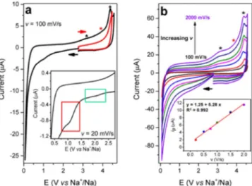
The CV of the solvent mixture shows some tiny reductive waves in the 2.2 V – 1.6 V region (Figure2ainset, green rectangle) while the main peak is located at ca. 1 V vs Na+/Na and becomes more evident by decreasing the scan rate from 100 mV/s to 20 mV/s (Figure S1(a) and Figure2ainset-red rectangle). When the potential is reversed, several unresolved oxidative waves appear at high potentials (2.8 V – 4.5 V vs Na+/Na, marked by asterisks). They are related to the oxidation of species produced by the electrolyte reductive decomposition, as confirmed by the absence of intense peaks in the simple oxidation scan of the solvent (red trace in Figure2a). By increasing the scan rate up to 2 V/s, two different waves could be revealed at ca. 3.2 V vs Na+/Na and 4.4 V vs Na+/Na (Figure2b, black asterisks and Figure S1(b)). The former could be attributed to the oxidation of an alkoxide species
Figure 2. CVs of an EC/DMC (1:1 in volume,+ 1 M NaPF6) solution at 25°C.
a, CVs at 100 mV/s toward low potentials (black) and high potential values (red). Both CVs correspond to the first scan after electrode polishing. The inset shows a zoom of the reduction waves at 20 mV/s. b, CVs at 100 mV/s (black), 200 mV/s (red), 500 mV/s (blue), 750 mV/s (magenta), 1000 mV/s (green), 1500 mV/s (navy) and 2000 mV/s (violet). The inset shows the ipvs v plot for
the oxidation peak at 3.2 V vs Na+/Na. A glassy carbon (3 mm diameter) was used as working electrode.
by comparison with a CV experiment of sodium methoxide in the same solvent (Figure S2), in agreement with a previous report.9However,
it should be noted here that the formation of hydroxide (OH−) instead of sodium methoxide should also be taken into account since this species could be simply produced by reduction of O2 traces in the
presence of water25–27within the 2.3 V – 1.5 V potential window28or
by H2O reduction at lower potentials.29,30The peak corresponding to
the OH−oxidation was reported to be at+ 0.75 V vs SCE in DMSO,27
corresponding to+ 0.45 V vs Ag+/Ag (+ 3.22 V vs Na+/Na). A similar peak was observed after polarizing the electrode at−2.7 V vs Ag+/Ag in a CH3CN solution of NaPF6 (1 M), hence providing
further support for the possible formation of hydroxides (Figure S3). The oxidation peak observed after addition of sodium methoxide in the DMC based electrolytes could then be simply related to OH−produced by the hydrolysis of alkoxide. Hence, to avoid any discrepancies, we label this product as simply ‘oxide’ throughout the manuscript. The elongated shape of the wave at 4.4 V vs Na+/Na suggests the existence of another weak and unresolved peak at ca. 3.9 V vs Na+/Na (red asterisk in Figure2aand Figure2b). If the peak intensity (ip) of the wave at 3.2 V vs Na+/Na is plotted as a function of the scan rate (v) a linear correlation is achieved, meaning that the oxide species is adsorbed (or simply precipitated) on the electrode surface (at least in a short term period) and effectively contributes to the anode SEI formation (Figure2binset and Figure S4).23Conversely, the peak at
ca. 4.4 V vs Na+/Na corresponds to the oxidation of an unknown species that is likely diffusive as observed by the linear relationship between the current and the square root of scan rate (Figure S5).
To investigate the potential required for the formation of the redox-active species produced by the electrolyte reduction, two different approaches were followed. In the first one, the electrode potential is cycled five times at 100 mV/s from 2.17 V vs Na+/Na to a particular value E (E< 2.17 V vs Na+/Na) in order to accumulate the degradation products. Then, an oxidative scan is performed to reveal by oxidation any new species produced in the reduction process. Starting from E= 1.37 V vs Na+/Na, an oxide is the first redox-active product to be observed (black asterisk in Figure S6), while for E= 0.57 V vs Na+/Na the peak at 3.90 V starts to grow and becomes the most intense one (red asterisk). According to a previous work, this wave could be reasonably attributed to the oxidation of an alkyl carbonate species deposed on the electrode surface (as shown by the linearity in the ipvs v plot of Figure3).9
Figure 3. a, linear scans at 100 mV/s (black), 200 mV/s (red), 500 mV/s (blue) and 1000 mV/s (magenta) of the SEI produced by five scans at 100 mV/s between 2.17 V vs Na+/Na and 0.07 V vs Na+/Na. b, ip vs v plot for the
oxidation peak at 3.9 V vs Na+/Na confirming the adsorption of the related species on the electrode surface. T= 25°C.
In the second method, the potential is varied at 1 V/s to a particular vertex value E and then this potential is held for one minute before recording the reverse oxidative scan at the same speed. The oxide re-oxidation peak was observed starting from E= 1.97 V vs Na+/Na (asterisk in Figure S7a). Overall, the cyclic voltammetry experiments with 1M NaPF6in EC-DMC showed no specific peak corresponding
to the reduction of EC at the negative electrode. The tiny reductive waves in the 2.2 V – 1.6 V (green rectangle in Figure2ainset) region may be associated with the O2traces and acid impurities present in
the electrolyte.30 The peak at ca. 1 V vs Na+/Na (red rectangle in
Figure2ainset) could be attributed to the reduction of H2O traces
or other impurities while only the huge reduction wave at very low potential (∼0 V vs Na+/Na) may be related to the decomposition of
the solvent.
Next, we studied the role of each additive by adding one by one consecutively and following the CV as explained before. After the ad-dition of vinylene carbonate (3% w/w), the CV at 100 mV/s (Figure S8a) did not reveal a significant change but an extra-peak was observed at ca. 0.5 V vs Na+/Na for v= 20 mV/s (Figure S8b). The same three redox-active products of electrochemical electrolyte decomposition were identified, although in a different ratio with respect to the VC-free case (asterisks in Figure S9). The oxide species starts to be detected at E< 1.57 V vs Na+/Na according to the first method (Figure S9) and at E< 1.87 V vs Na+/Na following the second approach (Figure S7b). The deposition of this species on the electrode surface was proved by the perfect linearity in the ipvs v plot (Figure S10). When NaODFB (0.5% w/w) was dissolved in the medium, an intense and purely diffu-sive (Figures S11, S12 and S13) reduction peak appeared at 0.97 V vs Na+/Na. The pre-peak at 1.08 V vs Na+/Na is probably related to the aging of the solution during the long-time experiment in glove box, as confirmed by the absence of this trace in a freshly prepared solu-tion (Figure S14) and in a propylene carbonate solusolu-tion of NaODFB (Figure S15). A drastic change was observed in the reverse scan at high potential values, implying that the SEI formation now highly de-pends on the presence of NaODFB (Figure S11). These re-oxidation waves have to be attributed to the oxidative SEI decomposition since they are missing in the simple oxidation scan recorded for the EC-DMC mixture (Figure S14, red trace). The formation of oxide species adsorbed (as shown in Figure S16) on the electrode was detected at 1.67 V vs Na+/Na and 1.87 V vs Na+/Na according to the first and second method, respectively (Figures S17 and S7c). With the addition of 1% (w/w) TMSPi, an intense peak (Ep= 3.86 V vs Na+/Na) related to the oxidation of TMSPi was observed at high potentials (Figure4), which is consistent with what reported in the literature.13The peak
Figure 4. CVs of an EC/DMC (1:1 in volume,+ 1 M NaPF6) solution
con-taining no additives (black), 3% VC (red), 3% VC+ 0.5% NaODFB (blue), and 3% VC+ 0.5% NaODFB + 1% TMSPi (magenta). The inset shows a zoom of the small reduction waves observed before the NaODFB reduction peak. All CVs correspond to the first scan after electrode polishing. v= 100 mV/s. T= 25°C.
related to the NaODFB reduction underwent a cathodic 90-mV shift (Ep= 0.88 V vs Na+/Na) and increased in intensity (Figure4). The pre-peak at 1.08 V vs Na+/Na disappeared, together with all the re-duction processes occurring before the NaODFB rere-duction. A similar phenomenon was also observed in PC electrolyte (Figure S18). No oxide species was detected before the foot of the NaODFB reduction wave for E> 1.27 V vs Na+/Na, as highlighted in Figures5aand Fig-ure S19 according to method 2 and method 1, respectively. A linear correlation between the peak current and the scan rate proved the de-position of this species on the electrode surface (Figure5a, inset). To conclude, among the three additives we studied here, solely NaODFB reduces within the studied potential window and participates directly on the SEI layer creation. VC and TMSPi seem to be involved only
Figure 5. a, CVs on an EC/DMC (1:1 in volume,+ 1 M NaPF6,+ 3% VC,
+ 0.5% NaODFB, +1% TMSPi) solution at 25°C (v = 1 V/s, one-minute holding of the vertex potential E). E= 1.57 V (black), 1.17 V (red), 0.92 V (blue), 0.67 V (magenta) and 0.47 V vs Na+/Na (green). The inset shows the ip
vs v plot for the oxide oxidation peak. b, CVs at 25°C (v= 1 V/s, one-minute holding of the vertex potential E= 1.27 V vs Na+/Na) of an EC/DMC (1:1 in volume,+ 1 M NaPF6,+ 3% VC,+ 0.5% NaODFB) solution without (black)
and with (red) 1% TMSPi.
Figure 6. Five potential cycles to produce the SEI (black) and following CV after five minutes resting (red). v= 100 mV/s. a, EC/DMC (1:1 in volume, + 1 M NaPF6) solution at 25°C. b, EC/DMC (1:1 in volume,+ 1 M NaPF6,
+ 3% VC) solution at 25°C. c, EC/DMC (1:1 in volume, + 1 M NaPF6,+
3% VC,+ 0.5% NaODFB) solution at 25°C. d, EC/DMC (1:1 in volume, + 1 M NaPF6,+ 3% VC, + 0.5% NaODFB, +1% TMSPi) solution at 25°C. e,
EC/DMC (1:1 in volume,+ 1 M NaPF6,+ 3% VC, + 0.5% NaODFB, +1%
TMSPi) solution at 55°C. The electrode was polished before the experiment for all the electrolyte compositions.
indirectly in the SEI layer formation. Notably, when hard carbon was used as working electrode instead of glassy carbon similar CVs were recorded, confirming the solidity of the approximation in the choice of the electrode material (Figure S20).
Importance of the additives.—To further probe the role of each
additive on the stability of SEI, we carried out a set of new cyclic voltammetry experiments, by following the qualitative CV study re-ported by Aurbach et al. with a partial modification.31For each
elec-trolyte composition the SEI was produced by performing five potential cycles at 100 mV/s to reach a minimum potential of 0.07 V vs Na+/Na (Figure S21). Due to the passivation phenomena, the measured cur-rent decreased cycle by cycle to stabilize before the fifth one. Then the electrode was left at open-circuit potential for five minutes, be-fore recording another CV (sixth cycle). If the formed SEI is stable without any dissolution during the 5 minutes rest period, there should be an overlap between the fifth and the sixth cycle without any new reduction peak. If there is a partial or complete dissolution of SEI during the rest period, the formed bare electrode surface will lead to new reduction processes on the sixth cycle. It is worthy to precise that an arbitrary rest period was chosen to compare the intrinsic passiva-tion ability of the different mixtures. Due to the huge difference in terms of electrolyte volume/electrode surface ratio with the real coin cells conditions, it is not possible to obtain in this way the exact SEI stability corresponding to the cycling experiments but only a prelim-inary comparison among electrolytes. A low stability of the SEI was observed for an EC/DMC 1:1 (v/v) solution containing 1 M NaPF6
(Figure6a) and with the addition of 3% VC (Figure6b), in agreement with previous data in the literature.32Conversely, the high SEI
stabil-ity recorded for an EC/DMC 1:1 (v/v) solution containing 1 M LiPF6
and 2% VC (Figure S22) matches with the good cycling stability of Li-ion batteries containing VC as additive.17Even after the addition
of 0.5% NaODFB to the electrolyte mixture (1M NaPF6+ 3% VC in
EC/DMC 1:1), a small reduction peak appears in the 6thcycle showing
ideal condition with sixth CV cycle overlapping exactly with the 5th
one was reached only after the addition of TMSPi as a last additive, pointing out the synergy among the different components (Figure6d). The role of vinylene carbonate as additive for Li-ion batteries and the importance of this molecule in the formation of stable interfaces have been already discussed in previous reports.17,33Moreover, the
re-activity of the C=C double bond toward polymerization reactions34,35
can be fundamental in the SEI creation even if the reduction of VC itself does not occur. Up to now, TMSPi is mainly known as a high-voltage additive since it can react directly with the traces of HF, H2O and PF5
responsible for the metal dissolution at the cathode and produce a pro-tective cathode film.12,36Interestingly, his role in the stabilization of
the anode SEI was studied in Li-ion batteries by Han et al.37NaODFB
was proposed as new electrolyte salt for Na-ion batteries in 2015, showing promising results in terms of rate capability and reversible capacity in Na/Na0.44MnO2half cells.38
As observed from our CV experiments, NaODFB is an essential additive for the SEI formation and an intense peak at 0.97 V vs Na+/Na is associated to the reduction of this species. The sharp-shape of this purely diffusive reduction wave demonstrates a partial self-inhibition of the glassy carbon surface during the electrochemical process.39
However, the NaODFB reduction peak is partially observed in CV after five minutes (Figure6c), suggesting that the SEI obtained at this stage is not completely stable. The huge improvement in stability registered after TMSPi addition can be rationalized by an in-depth analysis of the CV in Figure4, inset. In the absence of this additive, other parasitic reactions occur at relatively high potentials (E> 1.2 V vs Na+/Na) and are responsible for the formation of products including the redox-active sodium oxide species. This compound is mainly adsorbed on the electrode surface but not completely passivating, as demonstrated by the observation of the NaODFB reduction peak at a lower potential (Figure4). Conversely, in the presence of TMSPi no adsorbed oxide species is produced before the NaODFB reduction starts (Figure5b). In this regard, the positive effect (in terms of both thermodynamics and kinetics) of Lewis and Brønsted acids toward the reduction pro-cesses and reductive bond cleavages has been extensively discussed in the literature.40–42Some acidic impurities may thus be
responsi-ble for the reduction processes detected at E> 1.2 V vs Na+/Na. According to our results, the role of TMSPi as H2O, PF5 and
HF-scavenger to suppress side-reactions and control the SEI formation at the anode compartment appears fundamental. Moreover, some papers in the literature reported the O2-scavenging properties of TMSPi43,44
and this factor may be essential for controlling the first steps of the SEI formation at high potentials, by scavenging the O2traces in the
electrolyte responsible for the formation of adsorbed hydroxide. The significant increase of the NaODFB reduction peak upon TMSPi ad-dition (Figure4, Figure S14 and Figure S18) further points out the synergy between these two additives during the formation of the pas-sivating layer. This effect may be simply due to the limited production of adsorbed oxide at higher potential, as aforementioned. In the ab-sence of TMSPi a partial blocking of the electrode surface may occur, driving to a lowering of the NaODFB reduction peak current. By ad-dition of TMSPi, this partial passivation effect is suppressed and the NaODFB reduction peak may increase consequently. However, an-other possible explanation of this phenomenon has to be considered. The passivation process triggered by the reduction of NaODFB is rea-sonably associated to the deposition of products (denoted as P) on the electrode surface. In order to describe this system, we can propose the following simple mechanism:
ODFB−+ e−→← [ODFB]2− [1]
[ODFB]2− → P [2]
P → Adsorbed species [3]
TMSPi+ P → Dissolved species [4] The reaction between TMSPi and P (Eq.4) could compete with the formation of adsorbed species (Eq.3) and slow down the electrode
passivation, accounting for the increase of the NaODFB reduction peak. Keeping in mind that ODFB−is generally considered responsi-ble for the production of F−(labeled P in Eq.2)45and that TMSPi is
an efficient F−scavenger due to the formation of a strong Si-F bond (Eq.4),36,46the interaction between these two additives can produce
fluorotrimethyl silane ((CH3)3SiF). The evolution of this gas was
in-deed observed by mass spectrometry coupled to gas-chromatography during the formation cycle of our NVPF/C full cells at 55°C (Figure S23). Hence the formation of (CH3)3SiF could be essential to
con-trol the NaF-based SEI creation and avoid its excessive growth over cycling. Moreover a huge increase in the SEI resistance was regis-tered over cycling with NaODFB as only additive while the addition of TMSPi significantly suppressed the impedance growth (Figures1c
and1d). In order to further prove this assumption, the NaODFB re-duction was studied by CV in the presence of 1% tris (trimethylsilyl) phosphate (Figure S24a), bearing the same (CH3)3Si- group. Unlike
the TMSPi case, the tiny reduction waves in the 2.2 V–1.6 V region were not suppressed but a huge increase of the NaODFB reduction peak occurred. A similar experiment was then performed with small amounts of sodium tetraethyl borate, additive known to react with water and acids (Figure S24b).47The suppression of the parasitic
pro-cesses herein detected did not result in a significant increase of the NaODFB reduction peak, meaning that the peak enhancing with TM-SPi is mainly due to the F−scavenger properties of that additive. In summary, TMSPi can assist the SEI formation via NaODFB reduction by the formation of (CH3)3SiF and this synergy results in the limited
and controlled growth of the SEI.
Experiments at 55°C.—The electrochemical behavior of the
elec-trolyte was then studied at 55°C. At this temperature, the oxide species are produced in correspondence of the NaODFB reduction as well (Figure S25). The adsorption on the glassy carbon was confirmed by the linearity in the ip vs v plot (Figure S26). As evidenced in Figure6e, the passivating SEI formed by this electrolyte proved to be very stable over the time even at high temperature.
Electrochemical stability window of the SEI.—An analysis of the
electrochemical stability window of the SEI was carried out using cyclic voltammetry again, however by studying the oxidation process and allowing the formed SEI to oxidize partially/ completely. The ex-periment could be used to determine the maximum potential at which the carbon electrode can be fixed without destroying the formed SEI. Firstly, the passivating interphase was formed by performing five CV cycles at 100 mV/s from 1.27 V vs Na+/Na to 0.07 V vs Na+/Na. Then a CV was recorded going from 1.27 V vs Na+/Na to a partic-ular potential E (with E> 1.27 V vs Na+/Na) before reversing the scan to reach 0.07 V vs Na+/Na. The first segment of the CV should eventually oxidize the products of the electrolyte reduction while the second one should reveal if the passivating layer has been removed by oxidation (by the re-appearance of the NaODFB reduction peak). The experiment was carried out mainly for our best performing electrolyte 1M NaPF6in EC-DMC with 3% VC,+ 0.5% NaODFB, + 1% TMSPi
(Figure7). By slowly increasing the oxidation potential, the SEI layer was stable up to 3.57 V on oxidation. NaODFB reduction peak par-tially re-appears for E> 3.57 V vs Na+/Na indicating the loss of the passivation character at this potential value (Figure7). Analogously, the experiment at 55°C showed a partial decomposition of the SEI for E> 3.87 V vs Na+/Na (Figure S27).
To summarize, simple CV experiments with slight modifications were used to follow the reduction process of different additives, syn-ergy between different additives and also the solubility, electrochem-ical stability of the formed SEI layer. Equally, we extended our ap-proach to other systems as already demonstrated with electrolytes for the Li-ion technology (Figure S22). As a proof of concept, we have also carried out similar experiments for diglyme-based electrolyte with same additives and are described in supplementary information (Figure S28). Good results in terms of capacity retention were obtained at 25°C, with a significant improvement of the previously reported data for NVPF/C batteries in a glyme-based electrolyte.48
Figure 7. a, CVs at 100 mV/s of the SEI produced by five scans (not reported in the figure) between 1.27 V vs Na+/Na and 0.07 V vs Na+/Na for an EC/DMC (1:1 in volume,+ 1 M NaPF6,+ 3% VC, + 0.5% NaODFB, + 1% TMSPi)
solution at 25°C. Positive vertex potential= 1.47 V (black), 1.77 V (red), 2.07 V (blue), 2.37 V (magenta), 2.67 V (green), 2.97 V (navy), 3.27 V (violet), 3.57 V (purple), 3.77 V (wine), 4.07 V (dark yellow), 4.27 V (gray) and 4.47 V vs Na+/Na (light blue). A zoom of the NaODFB reduction peak is reported in b.
Conclusions
We herein reported a new electrolyte composition for Na-ion batter-ies consisting in an EC/DMC (1:1 in volume,+ 1 M NaPF6,+ 3% VC,
+ 0.5% NaODFB, + 1% TMSPi) solution. This formulation shows re-markable specific capacity retention and self-discharge performances at 55°C during cycling tests in coin cells, by using NVPF and C as cath-ode and ancath-ode, respectively. A cyclic voltammetry analysis led to an in situ probing of the SEI formation in these carbonate based solvents. Redox-active products of the reductive electrolyte fragmentation, such as RO−(where R= −alkyl or −H) and alkyl carbonate, were iden-tified as well as the redox potential required for their formation. The adsorption of these compounds on the electrode surface was proved by varying the scan rate in the CV experiment. Moreover, the elec-trochemical behavior of an EC/DMC (1:1 in volume,+ 1 M NaPF6)
solution containing vinylene carbonate (VC), sodium (oxalate) diflu-oro borate (NaODFB) and tris (trimethylsilyl) phosphite (TMSPi) as additives was elucidated. According to this study, NaODFB is reduced at 0.88 V vs Na+/Na and controls the interphase creation while TMSPi minimizes the O2reduction and other deleterious, parasitic and
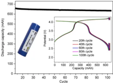
acid-boosted processes occurring at higher potentials and responsible for the formation of adsorbed RO−. Moreover, TMSPi contributes to con-trol the SEI creation by NaODFB and its growing over cycling. To the best of our knowledge, this contribution represents the first example reporting the CV study of the synergy between additives of a battery electrolyte. Furthermore, an evaluation of the SEI stability over time by cyclic voltammetry was proposed as method for a preliminary screen-ing of the electrolytes. Accordscreen-ing to this approach, the new electrolyte composition herein reported proved to be very promising in NVPF/C batteries for practical applications, in strong agreement with the bat-tery cycling tests. This patented electrolyte is presently successfully implemented in practical 18650 Na3V2(PO4)2F3/C cells (Figure8).
It enables excellent cycling and self-discharge performances at 55°C, however perfection has not been fully reached. Indeed, minor remain-ing improvement deals with the gas release durremain-ing the first cycle that we still need to minimize. A privileged direction we are being working on involves the chemical modification of the TMSPi additive.
Acknowledgments
J.-M.T. acknowledges funding from the European Research Coun-cil (ERC) (FP/2014)/ERC, Grant-Project 670116-ARPEMA. The
au-Figure 8. The cycling performances at 55°C of a 18650-type NVPF/C cell with the optimized electrolyte formulation containing VC, NaODFB and TM-SPi in EC/DMC (1:1 in volume,+ 1 M NaPF6). The cell was run at 55°C
for 10 cycles before a 1-week resting time at 100% SoC and the cycles after self-discharge are shown. The voltage-capacity curves at 20th, 40th, 60th, 80th
and 100thcycle are shown in the inset.
thors gratefully acknowledge Dr. Grégory Gachot for the GC-MS anal-ysis, Dr. Julien Rolland, Dr. Iona Moog for the 18650-type battery experiments and Nicolas Dubouis for fruitful discussion. There are no conflicts to declare. The optimized electrolyte formulation reported in this paper is patented; patent filing number: EP18305743, “New elec-trolyte composition for sodium ion battery,” G. Yan, J-M. Tarascon (2018).
ORCID
Claudio Cometto https://orcid.org/0000-0001-5737-9988
Guochun Yan https://orcid.org/0000-0002-1892-9331
Sathiya Mariyappan https://orcid.org/0000-0003-2851-5906
Jean-Marie Tarascon https://orcid.org/0000-0002-7059-6845
References
1. V. Etacheri, R. Marom, R. Elazari, G. Salitra, and D. Aurbach,Energy Environ. Sci.,
4, 3243 (2011).
2. M. D. Slater, D. Kim, E. Lee, and C. S. Johnson,Adv. Funct. Mater., 23, 947 (2013). 3. S. Roberts and E. Kendrick,Nanotechnol. Sci. Appl., 11, 23 (2018).
4. M. Gauthier, T. J. Carney, A. Grimaud, L. Giordano, N. Pour, H.-H. Chang, D. P. Fenning, S. F. Lux, O. Paschos, C. Bauer, F. Maglia, S. Lupart, P. Lamp, and Y. Shao-Horn,J. Phys. Chem. Lett., 6, 4653 (2015).
5. S. J. An, J. Li, C. Daniel, D. Mohanty, S. Nagpure, and D. L. Wood III, Carbon, 105, 52 (2016).
6. J. Song, B. Xiao, Y. Lin, K. Xu, and X. Li,Adv. Energy Mater., 8, 1703082 (2018). 7. R. Mogensen, D. Brandell, and R. Younesi,ACS Energy Lett., 1, 1173 (2016). 8. D. I. Iermakova, R. Dugas, M. R. Palacín, and A. Ponrouch,J. Electrochem. Soc.,
162, A7060 (2015).
9. G. Yan, D. Alves-Dalla-Corte, W. Yin, N. Madern, G. Gachot, and J.-M. Tarascon,J. Electrochem. Soc., 165, A1222 (2018).
10. G. Yan, K. Reeves, D. Foix, Z. Li, C. Cometto, S. Mariyappan, M. Salanne, and J.-M. Tarascon, Advanced Energy Materials, accepted.
11. Z. Zhang and S. S. Zhang, Eds., Rechargeable batteries: materials, technologies and
new trends, p. 712, Springer, Cham Heidelberg New York Dodrecht London, (2015).
12. Y.-K. Han, J. Yoo, and T. Yim,J. Mater. Chem. A, 3, 10900 (2015).
13. S. Mai, M. Xu, X. Liao, J. Hu, H. Lin, L. Xing, Y. Liao, X. Li, and W. Li,Electrochimica Acta, 147, 565 (2014).
14. P. Peljo and H. H. Girault,Energy Environ. Sci., 11, 2306 (2018).
15. K. Abe, H. Yoshitake, T. Kitakura, T. Hattori, H. Wang, and M. Yoshio,Electrochimica Acta, 49, 4613 (2004).
16. X. Zhang, R. Kostecki, T. J. Richardson, J. K. Pugh, and P. N. Ross,J. Electrochem. Soc., 148, A1341 (2001).
17. D. Aurbach, K. Gamolsky, B. Markovsky, Y. Gofer, M. Schmidt, and U. Heider,
Electrochimica Acta, 47, 1423 (2002).
18. G. Gachot, S. Grugeon, I. Jimenez-Gordon, G. G. Eshetu, S. Boyanov, A. Lecocq, G. Marlair, S. Pilard, and S. Laruelle,Anal. Methods, 6, 6120 (2014).
19. https://www.bio-logic.net/wp-content/uploads/20120113-Application-Note-38. pdf.
20. S. Pérez-Villar, P. Lanz, H. Schneider, and P. Novák,Electrochimica Acta, 106, 506 (2013).
21. G. Zampardi, F. La Mantia, and W. Schuhmann,RSC Adv., 5, 31166 (2015). 22. M. Tang, S. Lu, and J. Newman,J. Electrochem. Soc., 159, A1775 (2012). 23. A. J. Bard and L. R. Faulkner, Electrochemical methods: fundamentals and
applica-tions, 2nd ed., p. 833, Wiley, New York, (2001).
24. C. Bommier, T. W. Surta, M. Dolgos, and X. Ji,Nano Lett., 15, 5888 (2015). 25. D. L. Maricle and W. G. Hodgson,Anal. Chem., 37, 1562 (1965). 26. Pablo. Cofre and D. T. Sawyer,Anal. Chem., 58, 1057 (1986). 27. A. D. Goolsby and D. T. Sawyer,Anal. Chem., 40, 83 (1968).
28. P. Hartmann, C. L. Bender, M. Vraˇcar, A. K. Dürr, A. Garsuch, J. Janek, and P. Adelhelm,Nature Mater, 12, 228 (2013).
29. B. D. McCarthy, D. J. Martin, E. S. Rountree, A. C. Ullman, and J. L. Dempsey,
Inorg. Chem., 53, 8350 (2014).
30. M. Moshkovich, Y. Gofer, and D. Aurbach,J. Electrochem. Soc., 148, E155 (2001).
31. D. Aurbach and E. Granot,Electrochimica Acta, 42, 697 (1997).
32. S. Komaba, T. Ishikawa, N. Yabuuchi, W. Murata, A. Ito, and Y. Ohsawa,ACS Appl. Mater. Interfaces, 3, 4165 (2011).
33. L. El Ouatani, R. Dedryvère, C. Siret, P. Biensan, S. Reynaud, P. Iratçabal, and D. Gonbeau,J. Electrochem. Soc., 156, A103 (2009).
34. M. S. Newman and R. W. Addor,J. Am. Chem. Soc., 77, 3789 (1955). 35. G. Smets and K. Hayashi,J. Polym. Sci., 29, 257 (1958).
36. X. Qi, L. Tao, H. Hahn, C. Schultz, S. Nowak, S. Röser, J. Li, I. Cekic-Laskovic, B. R. Rad, and M. Winter,RSC Adv., 6, 38342 (2016).
37. T. Yim and Y.-K. Han,ACS Appl. Mater. Interfaces, 9, 32851 (2017).
38. J. Chen, Z. Huang, C. Wang, S. H. Porter, B. Wang, W. Lie, and H.-K. Liu,Chem. Commun., 51, 9809 (2015).
39. I. Bhugun and J.-M. Savéant,Journal of Electroanalytical Chemistry, 395, 127 (1995). 40. I. Bhugun, D. Lexa, and J.-M. Savéant,J. Phys. Chem., 100, 19981 (1996). 41. C. Costentin, S. Drouet, G. Passard, M. Robert, and J.-M. Savéant,J. Am. Chem. Soc.,
135, 9023 (2013).
42. M. H. V. Huynh and T. J. Meyer,Chem. Rev., 107, 5004 (2007).
43. D. J. Lee, D. Im, Y.-G. Ryu, S. Lee, J. Yoon, J. Lee, W. Choi, I. Jung, S. Lee, and S.-G. Doo,Journal of Power Sources, 243, 831 (2013).
44. T. Yim, S.-G. Woo, S. H. Lim, W. Cho, J. H. Song, Y.-K. Han, and Y.-J. Kim,J. Mater. Chem. A, 3, 6157 (2015).
45. J. Cha, J.-G. Han, J. Hwang, J. Cho, and N.-S. Choi,Journal of Power Sources, 357, 97 (2017).
46. M. L. Huggins,J. Am. Chem. Soc., 75, 4123 (1953).
47. J. B. Honeycutt and J. M. Riddle,J. Am. Chem. Soc., 83, 369 (1961).
48. K. Westman, R. Dugas, P. Jankowski, W. Wieczorek, G. Gachot, M. Morcrette, E. Irisarri, A. Ponrouch, M. R. Palacín, J.-M. Tarascon, and P. Johansson,ACS Appl. Energy Mater., 1, 2671 (2018).