SWAP, a novel EUV telescope for Space Weather
Jean-Marc Defise
a∗, Jean-Philippe Halain
a, David Berghmans
b, François Denis
a, Emmanuel Mazy
a,
Pierre Rochus
a, Tanguy Thibert
a, Jean-Hervé Lecat
a, Bogdan Nicula
b, Anik De Groof
c,
Jean-François Hochedez
b, Udo Schühle
d, Marie-Françoise Ravet
e, Frank Delmotte
ea
Centre Spatial de Liège, Université de Liège, Liege Science Park, 4013 Angleur, Belgium
bRoyal Observatory of Belgium, Avenue Circulaire, Uccle, Belgium
c
CPA, Katholieke Universiteit Leuven, Celestijnenlaan 200B, 3001 Leuven, Belgium
dMax-Planck-Institut für Sonnensystemforschung, Lindau, Germany
e
Institut d’Optique, Orsay, France
ABSTRACT
The SWAP telescope (Sun Watcher using Active Pixel System detector and Image Processing) is being developed to be part of the PROBA2 payload, an ESA technological mission to be launched in early 2008. SWAP is directly derived from the concept of the EIT telescope that we developed in the '90s for the SOHO mission. Several major innovations have been introduced in the design of the instrument in order to be compliant with the requirements of the PROBA2 mini-satellite: compactness with a new off-axis optical design, radiation resistance with a new CMOS-APS detector, a very low power electronics, an athermal opto-mechanical system, optimized onboard compression schemes combined with prioritization of collected data, autonomy with automatic triggering of observation and off-pointing procedures in case of solar event occurrence, … All these new features result from the low resource requirements (power, mass, telemetry) of the mini-satellite, but also take advantage of the specificities of a modern technological platform, such as quick pointing agility, new powerful on-board processor, Packetwire interface and autonomous operations.
These new enhancements will greatly improve the operations of SWAP as a space weather sentinel from a low Earth orbit while the downlink capabilities are limited. This paper summarizes the conceptual design, the development and the qualification of the instrument, the autonomous operations and the expected performances for science exploitation.
Keywords: EUV telescope, Solar corona, CMOS-APS, Space Weather
1. THE SWAP IMAGER ON THE PROBA2 MISSION
The PROBA2 platform1 is a technological mission to be launched in 2008 as secondary payload of a Rockot launcher,
together with the SMOS (Soil Moisture and Ocean Salinity) mission, for a nominal duration of 2 years in a sun-synchronous orbit at an altitude of 700-km. PROBA2 is a small satellite (130 kg) developed under an ESA General Support Technology Program (GSTP) contract by a Belgian consortium led by Verhaert Design & Development (Belgium) with two main objectives: perform an in-flight demonstration of new space technologies and support a scientific mission for a set of selected instruments2,3.
The Sun Watcher using Active Pixel System detector and Image Processing instrument4 (SWAP) is a compact instrument part of this mission that will observe the Sun in extreme ultraviolet (EUV) and demonstrate the performance of the CMOS-APS technology in space environment.
SWAP will provide images of the solar corona at a temperature of roughly 1 million degrees. This instrument was built upon the heritage of the Extreme ultraviolet Imaging Telescope6 (EIT) which monitors the solar corona since 1996. SWAP will continue the systematic CME (coronal mass ejection) watch program at an improved image cadence (typically 1 image every minute). With this higher cadence, SWAP will monitor events in the low solar corona that might be relevant for space weather. These events include EIT waves (global waves propagating across the solar disc
from the CME eruption site), EUV dimming regions (transient coronal holes from where the CME has lifted off) and filament instabilities (a specific type of flickering during the rise of a filament). SWAP will also take advantage of off-pointings provided by the agile PROBA2 platform to follow coronal mass ejections.
Fig 1. PROBA-2 platform with the SWAP instrument (covered with thermal blanket)
This new telescope concept demonstrates various improvements over the EIT design. In contrast to EIT, it is an off-axis Ritchey-Chrétien telescope within a restricted volume, with simpler baffling and smaller aperture. Due to the strict allocated mass and power resource budget (10 kg and average power of 5W), a deep optimization of the instrument electronics as well as a lightweight mechanical structure were necessary.
2. TELESCOPE DESIGN
The optical scheme of SWAP is a novel two-mirror off-axis Ritchey-Chrétien scheme5 offering numerous advantages:
good optical quality in minimum length, smaller and lighter mirrors for the given pupil area due to the absence of central obscuration, reduced aluminum foil filters diameter offering lower risk of damages during launch (no need to confine the filters under vacuum) and efficient baffling system avoiding the need of external baffle.
The optical layout is illustrated in Fig. 2. The main characteristics are: a 1173 mm focal length, 33 mm entrance pupil, 54 arcmin square field of view, 3.1 arcsec pixel field of view. The entrance pupil is located at the front side of the instrument, in close vicinity with a first aluminum foil filter. This configuration provides the smallest filter section for a given aperture. The primary mirror is elliptical (44 mm diam.), while the secondary mirror (28 mm diam.) is kept spherical for the sake of simplicity, as SWAP is developed under extreme schedule constrains. The optics are tilted to compensate the remaining aberrations. The paraxial focal length is adjusted to take into account distortion and fit with the field of view.
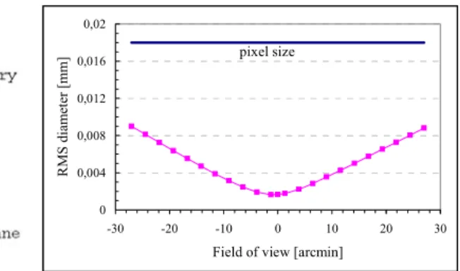
Fig. 3 shows the RMS spot diameter of the nominal design. The RMS spot diameter varies between 1.6 µm and 10.6 µm respectively for an on-axis object and for the corners of the field of view. The design is mainly limited by astigmatism induced by the spherical secondary mirror. The distortion is lower than 0.5 %.
A manufacturing and alignment budget has been derived to take into account all the contributions that can affect the optical quality. The result is a 17.1 µm RMS spot diameter in the worst case, for a pixel size of 18 µm. The main contributions come from the in-flight conditions (mainly the variations of the distance primary–secondary mirrors) and the spacecraft jitter (± 3 arcsec in the 0.2–10 Hz range) during the exposure time.
Fig. 2 SWAP optical scheme 0 0,004 0,008 0,012 0,016 0,02 -30 -20 -10 0 10 20 30
Field of view [arcmin]
R M S di amet er [ mm] pixel size
Fig. 3 RMS spot diameter of the nominal design in the FOV (values in mm).
3. INSTRUMENT DESCRIPTION
3.1 Optomechanical structureThe optical elements of SWAP are mounted on a lightweight invar optical bench that provides the necessary mechanical stability and insensitivity to thermal variations, better than 50-µm between the two mirrors in the wide temperature range (-40 to +70°C) that was considered for the PROBA-2 flight environment. SWAP is also using two flexible mounts for attachment on the spacecraft to avoid platform perturbations and keep the optical bench stability. The instrument is encased in a lightweight invar housing equipped with an aperture mechanism to preserve the optical cavity from external contamination during on-ground activities and launch phase. In order to limit the thermal exchange with the PROBA2 payload, the SWAP instrument is wrapped in a multilayer insulation thermal blanket (MLI).
Proximity Electronic Door assembly Primary Mirror Secondary mirror Optical bench Optical baffles Focal plane assembly with radiator
Fig. 4: SWAP instrument overview with its sub-systems
Taking advantage of the off-axis scheme that allows a simple and efficient baffling limited to the inter-mirror volume without stringent positioning tolerance, a two planar optical baffling structure has been implemented to avoid direct illumination of the detector. There is no need for an external baffle.
3.2 Optics and multilayer coatings
The two mirrors are made of Zerodur, polished with a micro-roughness below 0.5 nm to limit the EUV light diffusion that can extend and degrade the out-of-disk part of the image. After polishing, these mirrors were mounted in specific cells that have been separately qualified. Prequalification vibration tests identified the need to improve the fixation on the optical bench to maintain the mirrors in their aligned position.
Fig. 5: M1 flight and spare models before extraction from their master (courtesy AMOS SA)
Fig. 6: Qualification of the mirror mount in the CSL facilities Spectral filtering around the Fe IX/X emission line (17.4 nm) is achieved with EUV multilayer coatings deposited on the two mirrors, completed with two aluminum foil filters. These multilayer coatings play a dual role: they provide EUV reflectivity in nearly normal incidence, and they also ensure the fine spectral tuning of the instrument. Mo/Si multilayers have been deposited on the SWAP primary M1 and secondary M2 mirrors of the flight and spare sets by using the ion beam sputtering process developed for the EUVI 4 channels telescopes of the STEREO-SECCHI instrument7. According to the specifications of the optical design of the mirrors, the range of the incidence angles is 1.7° to 3.6° for M1 and 3.2° to 6.2° for M2. Simulations predicted that no lateral gradient of thickness was needed to compensate the angular incidence variation. A multilayer structure was designed for both M1 and M2 in order to get a constant value of the reflectance at 17.4 nm on their angular incidence ranges. Multilayer coatings were deposited on all mirrors which were preliminary bonded on their mechanical mounts. A mask was designed and mounted in the deposition chamber in front of the mirror in order to reduce thickness non-uniformities lower than 1% on the total mirror area. The deposition rate and layer thickness were controlled with a quartz microbalance during the deposition process.
In order to adjust the wavelength peak position of the Mo/Si coatings, calibration samples and witness samples deposited in the same run as the mirrors respectively were characterized. The multilayer spacings were deduced from grazing X-ray reflectometry @0.154 nm. The EUV reflectivity at the operational wavelength for calibration and witness samples was measured at the PTB synchrotron facility8 (Berlin) and on the EUV plasma source reflectometer CEMOX (Centrale
de Métrologie des Rayons X- Orsay). A cross-analysis of the data provided by both methods compared to additional measurements done on the BEAR line of the ELETTRA synchrotron facility9 (Trieste) allows to evaluate the multilayer
performances. The experimental uncertainties on the peak position determination due to the deposition procedures and the reflectivity measurements are estimated at ± 0.1 nm. The reflectance was deduced from a normalization with PTB data with an accuracy of ± 2.00%. Within these margins it can be considered that the EUV coatings satisfy the specifications for each of the two flight and spare SWAP mirror sets.
Table 1: Performances of mirror witness samples for the 2 sets of mirrors (central wavelength of the bandpass and maximum reflectivity)
λ max (nm) Reflectivity (%) Bandwidth(nm) FM1 17.47 ± 0.1 nm 40.80 ± 2.00 1.3 FM2 17.62 ± 0.1 nm 39.50 ± 2.00 1.4 SM1 17.57 ± 0.1 nm 37.90 ± 2.00 1.3 SM2 17.42 ± 0.1 nm 38.20 ± 2.00 1.2
Fig. 7. One of the 2 sets of SWAP mirrors after coating
3.3 EUV Filters
The overall spectral purity and visible light rejection is achieved with the addition of 2 EUV foil filters. One is located at the instrument entrance (38-mm diameter) to avoid excessive heating of the primary mirror, and the second filter is inserted near the focal plane (28-mm diameter) to eliminate any residual visible straylight from potential light leaks in the front housing or the entrance filter itself.
Two types of filters are used in the instrument. The front filter is an aluminum foil deposited on a polyimide film preventing grid diffraction effects and the rear filter is using a foil supported by a nickel grid (70-lpi Ni mesh) that will produce small shadow artifacts that can easily be corrected10 during data processing. To ensure that these aluminum foils
(150-nm thickness) will survive the venting during launch ascent and launch vibrations (including acoustic effects), a development program has been set up to evaluate the pressure load on the filters and define solutions to provide a safe environment at the level of the filters. Air flow studies, combined with vibration analyses, followed by real tests on a mockup provided useful measurements that were used to define venting holes (number, location, size) and specific acoustic baffles.
Fig. 8. SWAP front and rear aluminum foil filters
3.4 Telescope alignment
Alignment of off-axis telescopes is a difficult task mainly due to the high number of degrees of freedom to manage. The alignment was based on interferometric measurement with the secondary mirror as compensator. In the present case, the spherical secondary mirror eased the alignment process, but introduced some residual astigmatism. This alignment was performed using a dummy focal plane assembly (FPA) representative of the real one in terms of focal plane location to allow interferometric measurements (Fig. 9). A resulting surface front error of λ/30 RMS (at 633 nm) has been achieved, much better than the minimum alignment quality requirement.
An alignment reference cube is used to materialize the optical axis and allow for co-alignment with LYRA radiometer on the PROBA2 platform. This co-alignment has been characterized and used to align the instruments during their integration on the payload.
3.5 Focal Plane Assembly
The images are recorded on a CMOS-APS detector mounted in a dedicated focal plane assembly (FPA). The FPA holds the detector at the precise location of the focal plane, but also includes a passive cooling system made of a radiator viewing cold space, a heating system to periodically decontaminate the detector, a cold cup to trap the contaminants, a set of diodes for in-flight calibration, and the readout electronics that operates, reads and transfers the image data to a data processing board located inside the central computer.
The detector is a 1024x1024 pixel HAS device11 produced by Cypress/FillFactory (B) with a scintillator coating for
enhancing its responsivity in the EUV range. This is a CMOS-APS device, in contrast to classical CCD technology, ending a development program at ESA. This detector provides very interesting features promising to be very profitable for imaging in space: shutterless operation, improved noise reduction, destructive and non-destructive readout modes, subframe readout, resistance to radiations and low power due to its CMOS technology. The new CMOS-APS detector allows for non-destructive readout operations thus reducing the static fixed pattern noise and the kTC noise.
3.6 SWAP Electronics
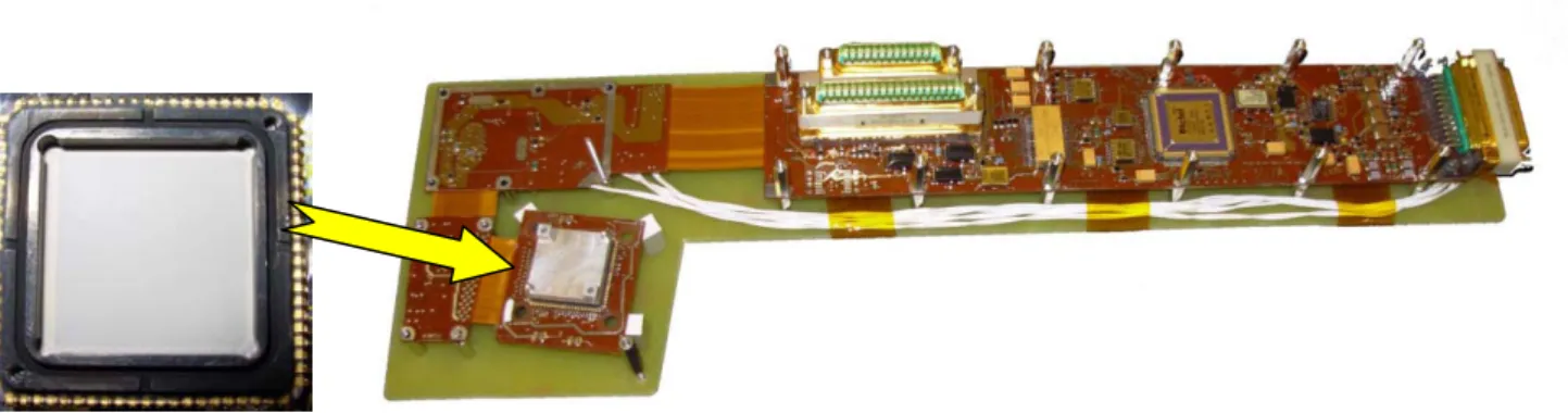
The readout proximity electronics consists of a flex-articulated multilayer printed circuit board which is encapsulated all along the body of the telescope and within the FPA for the CMOS sensor part. The CMOS is operated by an FPGA and is directly soldered on the electronic board. The proximity board has a one-picture buffering capability using SRAM memory and is able to retransmit data in case of failure on its balanced transmission line (RS422).
Fig. 10. SWAP detector (left) and Proximity Electronics (right)
The proximity electronics is connected to two cold-redundant dedicated FPGA-based compact-PCI acquisition boards, the MCPM (Memory Compression and Packetization Module) which are plugged in the central computer of PROBA2, the ADPMS. The MCPM communicates directly with the satellite telemetry using a derivative of the SpaceWire standard (Packetwire). It also has two-bit error detection and one-bit error correction capabilities. The software running in the ADPMS will manage the SWAP data, with a compression module and a set of automatic event detection algorithms and data processing (cosmic ray removal, weak pixel compensation…). The data are stored in the 512MB effective SDRAM memory array of the MCPM and are prepared for downlink according to a set of prioritization rules, in order to dedicate the limited transfer rate to the most interesting data.
The different stabilized voltages are provided by a power conditioning unit (IIU), shared by SWAP and the LYRA radiometer. This standalone unit is mounted on the platform nearby the 2 payload instruments. It is made of two independent modules, one for SWAP and one for LYRA so that both units can be operated independently, converting the 28V unregulated voltage delivered by the satellite power supply bus into several regulated voltages for the different needs of the payload units. Both IIU modules have a DC/DC flyback topology and are controlled via optocouplers by MCPM registers.
3.7 Thermo-mechanical design
The thermal and mechanical design of SWAP has been studied to keep the instrument within adequate temperature range and to provide the required strength to mechanical loads. Specific studies were conducted to optimize the control of the mirrors alignment during thermal excursions and the cooling of the CMOS detector. This will reduce the thermal noise associated to the dark current and will ensure a valuable signal over noise ratio under all operating conditions.
The thermo-mecanical studies of the structure were conducted with SAMCEF; thermics and thermo-mechanics of the focal plane assembly with EFD Lab, and the full instrument was thermally modelled in ESARAD/ESATAN.
Fig. 11. Thermo-mechanical deformation of the structure (SAMCEF). The feet design uses titanium elasticity to relax the stress induced in the SWAP bench by the thermo-elastic deformation of the PROBA-II platform (courtesy AMOS SA).
Fig. 12. FPA thermal design (EFD.Lab). The FPA includes the CMOS sensor, a cold cup, a cold finger, baking heaters, calibration LEDs and proximity electronics, tightly packed in a straylight-tight box under the cooling radiator (courtesy OIP NV).
The full SWAP thermal model was improved after STM (structural thermal model) thermal tests, and further correlated with FM test campaign. In addition to a design aid, it provides now unique information about in-flight temperatures. A 5-nodes reduced model was derived from the full model and integrated inside the PROBA2 platform thermal model, in order to improve the definition of the thermal interfaces.
The thermal control of the instrument is strictly passive. The bench is thermally driven by the platform through the rear foot. Other interactions are limited by the MLI cover. The front door mechanism, exposed to the direct Sun, is white painted to limit the heat absorption. The front filter also helps, reflecting the Sun light to space. The CMOS detector is cooled by a dedicated radiator.
Fig. 13. Thermal model of SWAP FM during Thermal Balance tests (ESARAD)
3.8 Modelling predictions
The design of the structure and the FPA were studied with the help of a finite element model, predicting overall stiffness and strain levels. The vibration runs confirmed that the first global eigen mode, i.e. with an effective mass larger than 5% of the total, has a frequency significantly larger than the minimum requested 150Hz limit, with actually 350Hz (Fig. 14). The optical alignment check after the vibration runs showed no slippage or no deformation of the instrument on the feet interface and no internal misalignment confirming the reliability of the mechanical design.
The thermal model was initially correlated with thermal tests on the Structural Thermal Model. It was proofed later during the Flight Model thermal tests, giving predictions with an accuracy better than 2°C in hot (Tmax = +55°C) and cold
(Tmin = -52°C) extreme cases. The detector was the exception, with a temperature 8°C higher than predicted due to
overestimation of conductive links. This was the first thermal tests with the proximity electronics inside the FPA. Both full and reduced thermal models were updated accordingly. Subsequent tests at platform level confirmed the adequacy of the correction, with a match of predictions and measurements now better than 2°C on the whole model.
The hot and cold cases represent the hottest and coldest situations that could happen in orbit, with usual safety margins. This accounts for many parameters that affect the temperature levels, like the spacecraft power variations, the orbit position, the astronomical season, the Sun variations, the paintings degradation with UV during lifetime, etc. The
instrument is designed to survive and function under these extreme temperatures. The validation of the thermal model with the FM tests is the last step for reliable predictions in the whole range between hot and cold extremes.
Fig. 14. First eigen mode of the SWAP structure: a general rotation around its main axis.
3.9 Final assembly
Fig. 15 shows the assembled SWAP instrument. The door is white painted to limit the absorbed solar flux. The radiator is also white painted for higher IR emissivity with low visible absorptivity, as it can view visible light from the Earth. The reference alignment cube, located in front of the instrument, is also visible on this picture, left side of the cover hinge.
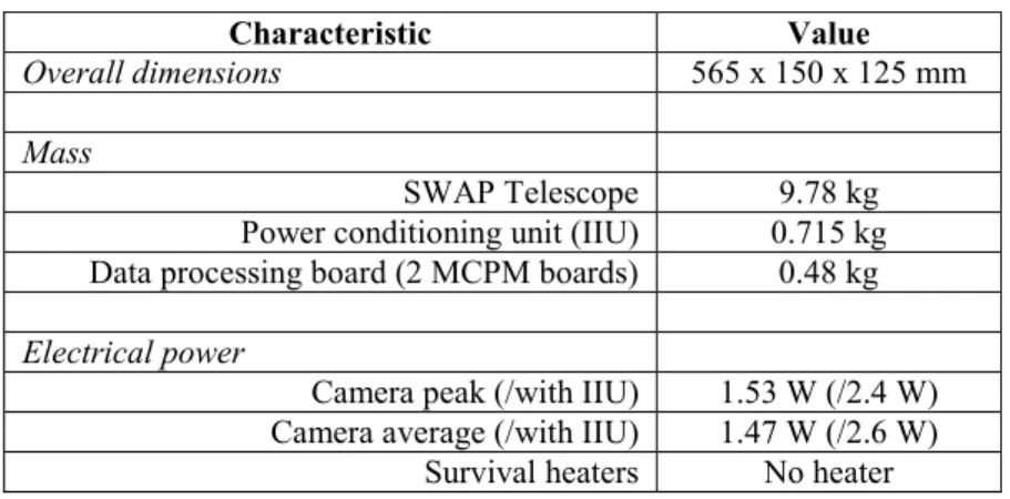
Fig. 15. SWAP assembled instrument on the shaker, door closed and open (showing the front foil filter). Table 2 summarizes the main resources needed for SWAP on the PROBA2 platform.
Table 2. SWAP Resource parameters
Characteristic Value
Overall dimensions 565 x 150 x 125 mm
Mass
SWAP Telescope 9.78 kg Power conditioning unit (IIU) 0.715 kg Data processing board (2 MCPM boards) 0.48 kg
Electrical power
Camera peak (/with IIU) 1.53 W (/2.4 W) Camera average (/with IIU) 1.47 W (/2.6 W)
4. INSTRUMENT ENVIRONMENTAL TESTS
The full assembly, integration and all the environmental tests were performed in the facilities of the Centre Spatial de Liège (CSL Belgium).
The different subsystems were vacuum baked out before assembly in order to prevent contamination from outgassing. Then the full instrument was assembled and prepared for the environmental tests (see Fig. 16 and Fig. 17). The telescope was vibrated according to specific qualification levels specified by the PROBA2 platform. These tests were conducted with the hardware in the real flight configuration, with the aluminum foil filters and the aperture door closed for launch. Several post-vibration key checks were performed to verify the integrity of the foil filters and to check that no misalignment occurred between the SWAP reference optical cube and another optical reference on the vibration mechanical interface. All the verifications were successful.
Fig. 16. SWAP environmental qualification (vibrations and thermal vacuum) in CSL facilities (Liège, B)
Fig. 17. SWAP and LYRA experiments during EMC test in ETS facilities (at ESA/ESTEC)
Following the mechanical test, the instrument was installed in a vacuum chamber at CSL, in a specific thermal enclosure used to represent the different platform temperatures that will be seen by SWAP. The solar input was represented by an equivalent heater load. This allowed to reproduce thermal balance conditions and correlate the thermal mathematical models. In a second step, thermal vacuum cycles were applied to the instrument with functional verifications to demonstrate the thermal qualification of the hardware. This thermal test verified the capability of the SWAP instrument to operate satisfactorily in vacuum at expected hot and cold temperatures (operational thermal cycles) and the survival in non-operational conditions without degradation of functional performance. These tests were followed by EMC/EMI tests. They were conducted in the ETS facilities at ESTEC, with the power conditioning unit and the LYRA radiometer. All the EMC requirement were verified.
5. INSTRUMENT END-TO-END CALIBRATION
The calibration of SWAP was performed at the EUV synchrotron beam of PTB-BESSY8 (Berlin) just before delivery to
the platform. It was the only opportunity to perform an end-to-end test of the complete SWAP system in front of EUV light before launch. Several subsystems were previously EUV calibrated in order to verify their performance, but also to build a first instrument response model. Testing the complete chain was a very important step to demonstrate the good performance of the system.
The PTB Bessy facility is using the synchrotron radiation to feed a monochromator and deliver EUV light in the SWAP instrument entrance section. The calibration procedure was defined taking into account the small physical size of the EUV beam compared to the instrument entrance section. The main objectives were to perform a pupil scan, to obtain the instrument response (photometry, linearity), noise evaluation, spectral band-pass and characterize the filter grid. SWAP is mounted on a translation and rotation table, allowing for covering the field of view and the centering of the pupil. Fig. 18 shows an enlargement of the PTB-BESSY beam image on the SWAP detector, outlining the grid support of the aluminum filter when illuminated with a narrow collimated beam.
Fig. 18 PTB-BESSY beam spot on SWAP detector (detail)
Fig. 19 SWAP linearity in non destructive readout mode
The photometry was measured in 6 locations of the pupil. The comparison confirmed the good uniformity of the multilayer coatings.
Linearity was evaluated for different level of illumination, in different parts of the detector. Fig. 19 shows the linearity at the centre of the detector.
The spectral response of the full instrument has been carefully characterized, using the monochromator of the PTB Bessy line. Fig. 20 gives the SWAP spectral transmission over the 16.5nm to 20nm spectral range, highlighting the maximum response at 17.4 nm. 16.5 17 17.5 18 18.5 19 19.5 20 0 1 2 3 4 5 6 7 8 9 x 10⁻⁴ wavelength (nm) effi ci en cy ( D N s /p h oto n ) calibration data interpolation
Fig. 20 SWAP measured spectral transmission curve The instrument throughput is an important parameter. It is a driver to define the exposure time and the residual effects of the spacecraft jitter. The throughput has been measured at 1000 photon/DN in 12-bit mode, leading to 15 sec typical exposure time for solar corona imaging. The thermal noise in the warmest case conditions is limited to 2 DN.
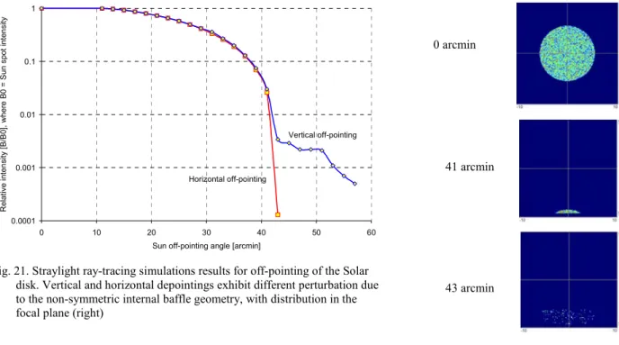
Straylight is a concern for the SWAP instrument. During nominal operations, straylight risk is mainly produced by visible light leaks. There are 105 times more visible solar photons than 17.4 nm solar photons. This rejection is achieved
with the 2 aluminum filters, and by a light leak-proofed housing. During off-pointing sequences, the solar disk will be outside the field of view, but still entering the instrument. It is the main (EUV) straylight contributor. The straylight measurements performed with the PTB-BESSY EUV beam have shown that the instrument rejects the light out of the field of view with an efficiency of the order of 103, matching with the ray-tracing simulations conducted for similar input
beam. Ray-tracing computations have been extended to solar disk input. Fig. 21 shows the Solar disk for some off-pointing values on the detector location (axis in mm).
0.0001 0.001 0.01 0.1 1 0 10 20 30 40 50 60
Sun off-pointing angle [arcmin]
Re la tive in te n si ty [B /B0 ], w h er e B 0 = Su n sp ot in te n si ty Horizontal off-pointing Vertical off-pointing
Fig. 21. Straylight ray-tracing simulations results for off-pointing of the Solar disk. Vertical and horizontal depointings exhibit different perturbation due to the non-symmetric internal baffle geometry, with distribution in the focal plane (right)
6. INNOVATIVE AND AUTONOMOUS OPERATIONS
SWAP data will benefit from series of innovations that have been implemented during the development of the instrument and platform flight software. Most of them can be considered as demonstrators for future space missions.
PROBA2 will fly with the new 100 MHz AT697 LEON II microprocessor. It will be the first satellite mission to fly ESA’s new high performance, radiation hardened processor which is expected to be used for many other ESA missions such as Solar Orbiter. The extra computing power delivered by the new microprocessor will make possible to implement some basic on-board image processing capabilities dedicated to SWAP data, and benefit from some automatic processing and autonomous operations.
The SWAP images are stored in the MCPM. Before being compressed, discontinuities (cosmic rays) are removed and weak pixels are compensated by on-board routines based on flat field information. These operations will avoid JPEG compression artefacts. When JPEG algorithm is selected, the 12-bit pixel values are re-coded to 8-bit before compression. A sophisticated re-coding12 algorithm is used to minimize the data alteration.
When default imaging mode is used with full images at 1-minute cadence, SWAP will produce more data than what can be sent to the ground stations. An automatic data prioritization process has been defined in order to make the best use of the limited telemetry bandwidth. This algorithm aims to identify potentially interesting solar events and transfer the associated data to the ground in higher priority.
An interesting feature of PROBA2 has been diverted to improve the coronal mass ejection (CME) observation program. PROBA2 is a 3-axis stabilized platform with agile capabilities. This means that PROBA2 can quickly change the pointing of SWAP in any direction. The nearly real time on-board processing of the SWAP images will allow detecting eruption of material from Sun’s surface in a set of predefined sectors. When any of such event is detected, SWAP MCPM triggers an off-pointing procedure, in order to follow the CME in a given direction. This exploratory mode will enlarge the field of view of SWAP by a factor 3, although the instrument has straylight limitations as well as relatively
0 arcmin
41 arcmin
limited throughput for faint EUV emissions observed from CME. Such event detection can also trigger an increase in temporal cadence and a specific windowing mode that will give access to scientific analysis of the first stage of CME accelerations.
7. CONCLUSIONS
SWAP is a science instrument with several technological challenges. However, it is built upon proofed heritage that should ensure that SWAP will be an effective and efficient space weather tool.
The opportunity offered by the PROBA2 technological platform has been taken to provide on one side science data, and on another side, to demonstrate several new concepts such as a new off-axis EUV optical scheme, the use of a CMOS detector for EUV imaging in space, a lightweight INVAR optical bench, and on-board data processing.
To conclude, the SWAP payload on PROBA2 will provide
• demonstration of new technologies and new operation concepts;
• preparation for new missions such as EUI/Solar Orbiter (ESA) and Kuafu (CNSA); • valuable inputs for space weather forecasting;
• data for new scientific researches;
• continuation to the solar survey of the aging SOHO mission with improved temporal resolution; • support for the SECCHI/STEREO mission.
ACKNOWLEDGEMENTS
The SWAP instrument was developed by Centre Spatial de Liège (Université de Liège, B) in collaboration with the Royal Observatory of Belgium (B). Support for calibration was provided by the Max Planck Institute (G). Belgian activities are funded by the Belgian Federal Science Policy Office (BELSPO), through the ESA/PRODEX program for the payload instruments, and the ESA/GSTP program for the platform.
REFERENCES
1. F. Teston, R. Creasey, J. Bermyn, K. Mellab, “PROBA: ESA’s Autonomy and Technology Demonstration Mission”, Proceedings of the 13th Annual AIAA/USU, Conference on Small Satellites, August 23 – 26, 1999.
2. P. Rochus, J.M Defise, et al., “PROBA II Payload: A Belgian mini space Weather Observatory”,.55th International Astronautical Congress, 2004 (4-8 October), Vancouver, Canada.
3. J.M. Defise, J.H. Lecat, J.H., Y. Stockman et al.,“SWAP and LYRA: space weather from a small spacecraft”, Proceedings of 2nd International Conference of Recent Advances in Space Technologies, 2005.
4. J.M. Defise, D. Berghmans, J.F. Hochedez et al, “SWAP: Sun Watcher using APS detector on-board PROBA-2, a
new EUV off-axis telescope on a technology demonstration platform”, SPIE, 5171-45, 2003.
5. J.M. Defise et al, “SWAP, Sun Watcher with a new EUV telescope on a technology demonstration platform”. ICSO Conference, 2004.
6. JP. Delaboudinière et al., EIT: Extreme-UV imaging telescope for the SOHO mission; Solar Physics 162: 291-312, 1995.
7. M.F. Ravet et al , “Ion beam deposited MoSi multilayers for EUV Imaging applications in Astrophysics”, Proc. SPIE vol 5250-12 (2003) pp. 99-108.
8. http://www.bessy.de/ 9. http://www.elettra.trieste.it/
10. J.M. Defise, F. Clette, F. Auchere, In-flight characterization and compensation of the optical properties of the EIT
instrument, , SPIE 3765, 1999
.
11. B. Dierickx, G. Meynants, D. Scheffer, "Near 100% fill factor CMOS active pixels", in IEEE CCD & AIS workshop, Brugge, Belgium, 5-7 june (1997); Proceedings p. P1