HAL Id: hal-01863733
https://hal.archives-ouvertes.fr/hal-01863733
Submitted on 29 Aug 2018
HAL is a multi-disciplinary open access
archive for the deposit and dissemination of
sci-entific research documents, whether they are
pub-lished or not. The documents may come from
teaching and research institutions in France or
abroad, or from public or private research centers.
L’archive ouverte pluridisciplinaire HAL, est
destinée au dépôt et à la diffusion de documents
scientifiques de niveau recherche, publiés ou non,
émanant des établissements d’enseignement et de
recherche français ou étrangers, des laboratoires
publics ou privés.
Parasitic Inclinations in Cable-Driven Parallel Robots
using Cable Loops
Saman Lessanibahri, Philippe Cardou, Stéphane Caro
To cite this version:
Saman Lessanibahri, Philippe Cardou, Stéphane Caro. Parasitic Inclinations in Cable-Driven Parallel
Robots using Cable Loops. The 28th CIRP Design Conference, May 2018, Nantes, France. pp.296-301,
�10.1016/j.procir.2018.02.013�. �hal-01863733�
ScienceDirect
Available online at www.sciencedirect.com
ScienceDirect
Procedia CIRP 00 (2017) 000–000www.elsevier.com/locate/procedia
2212-8271 © 2017 The Authors. Published by Elsevier B.V.
Peer-review under responsibility of the scientific committee of the 28th CIRP Design Conference 2018.
28th CIRP Design Conference, May 2018, Nantes, France
A new methodology to analyze the functional and physical architecture of
existing products for an assembly oriented product family identification
Paul Stief *, Jean-Yves Dantan, Alain Etienne, Ali Siadat
École Nationale Supérieure d’Arts et Métiers, Arts et Métiers ParisTech, LCFC EA 4495, 4 Rue Augustin Fresnel, Metz 57078, France
* Corresponding author. Tel.: +33 3 87 37 54 30; E-mail address: [email protected]
Abstract
In today’s business environment, the trend towards more product variety and customization is unbroken. Due to this development, the need of agile and reconfigurable production systems emerged to cope with various products and product families. To design and optimize production systems as well as to choose the optimal product matches, product analysis methods are needed. Indeed, most of the known methods aim to analyze a product or one product family on the physical level. Different product families, however, may differ largely in terms of the number and nature of components. This fact impedes an efficient comparison and choice of appropriate product family combinations for the production system. A new methodology is proposed to analyze existing products in view of their functional and physical architecture. The aim is to cluster these products in new assembly oriented product families for the optimization of existing assembly lines and the creation of future reconfigurable assembly systems. Based on Datum Flow Chain, the physical structure of the products is analyzed. Functional subassemblies are identified, and a functional analysis is performed. Moreover, a hybrid functional and physical architecture graph (HyFPAG) is the output which depicts the similarity between product families by providing design support to both, production system planners and product designers. An illustrative example of a nail-clipper is used to explain the proposed methodology. An industrial case study on two product families of steering columns of thyssenkrupp Presta France is then carried out to give a first industrial evaluation of the proposed approach.
© 2017 The Authors. Published by Elsevier B.V.
Peer-review under responsibility of the scientific committee of the 28th CIRP Design Conference 2018. Keywords: Assembly; Design method; Family identification
1. Introduction
Due to the fast development in the domain of communication and an ongoing trend of digitization and digitalization, manufacturing enterprises are facing important challenges in today’s market environments: a continuing tendency towards reduction of product development times and shortened product lifecycles. In addition, there is an increasing demand of customization, being at the same time in a global competition with competitors all over the world. This trend, which is inducing the development from macro to micro markets, results in diminished lot sizes due to augmenting product varieties (high-volume to low-volume production) [1]. To cope with this augmenting variety as well as to be able to identify possible optimization potentials in the existing production system, it is important to have a precise knowledge
of the product range and characteristics manufactured and/or assembled in this system. In this context, the main challenge in modelling and analysis is now not only to cope with single products, a limited product range or existing product families, but also to be able to analyze and to compare products to define new product families. It can be observed that classical existing product families are regrouped in function of clients or features. However, assembly oriented product families are hardly to find.
On the product family level, products differ mainly in two main characteristics: (i) the number of components and (ii) the type of components (e.g. mechanical, electrical, electronical).
Classical methodologies considering mainly single products or solitary, already existing product families analyze the product structure on a physical level (components level) which causes difficulties regarding an efficient definition and comparison of different product families. Addressing this
Procedia CIRP 70 (2018) 296–301
2212-8271 © 2018 The Authors. Published by Elsevier B.V.
Peer-review under responsibility of the scientific committee of the 28th CIRP Design Conference 2018. 10.1016/j.procir.2018.02.013
© 2018 The Authors. Published by Elsevier B.V.
Peer-review under responsibility of the scientific committee of the 28th CIRP Design Conference 2018.
Procedia CIRP 00 (2018) 000–000 www.elsevier.com/locate/procedia
28th CIRP Design Conference, May 2018, Nantes, France
Parasitic Inclinations in Cable-Driven Parallel Robots using Cable Loops
Saman Lessanibahri
a, Philippe Cardou
b, St´ephane Caro
caCentrale Nantes, Laboratoire des Sciences du Num´erique de Nantes, UMR CNRS 6004, 1, rue de la No¨e, 44321 Nantes, France bLaboratoire de robotique, D´epartement de g´enie m´ecanique, Universit´e Laval, Qu´ebec, QC, Canada
cCNRS, Laboratoire des Sciences du Num´erique de Nantes, UMR CNRS 6004, 1, rue de la No¨e, 44321 Nantes, France
∗Corresponding author. Tel.: +33-240-376-925; fax: +33-240-376-925. E-mail address: [email protected]
Abstract
Cable-Driven Parallel Robots (CDPRs) also noted as wire-driven robots are parallel manipulators with flexible cables instead of rigid links. A CDPR consists in a base frame, a Moving-Platform (MP) and a set of cables connecting in parallel the MP to the base frame. CDPRs are well-known for their advantages over the classical parallel robots in terms of large workspace, reconfigurability, large payload capacity and high dynamic performance. In spite of all the mentioned advantages, one of the main shortcomings of the CDPRs is their limited orientation workspace. The latter drawback is mainly due to cable interferences and collisions between cables and surrounding environment. Hence, a planar four-Degree-of-Freedom (DoF) under-constrained CDPR with an articulated MP is introduced and studied in this paper. The end-effector is articulated through a cable loop, which enables the robot to obtain a modular pose determination, namely orientation and positioning. As a result, the mechanism under study has an unlimited and singularity-free orientation workspace in addition to a large translational workspace. It should be noted that some unwanted rotational motions of the moving platform, namely, parasitic inclinations, arise due to the cable loop. Finally, those parasitic inclinations are modeled and assessed for the mechanism at hand.
c
�2018 The Authors. Published by Elsevier B.V.
Peer-review under responsibility of the scientific committee of the 28th CIRP Design Conference 2018. Keywords: Cable-Driven Parallel Robots, Cable Loop, Kinematics, Large Workspace;
1. Introduction
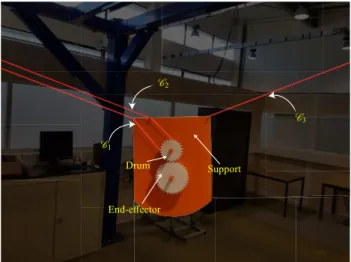
One advantage of cable-driven parallel robots that has not yet been fully exploited is the possibility of using the cables to transmit power directly from motor fixed to the frame to the moving platform. This power can then be used to actuate a tool or to control additional degrees of freedom such as rotations over wide ranges [14], for example. In this article, we study the simplest expression of a bi-actuated cable circuit, namely, a ca-ble loop, for controlling rotations of the CDPR end effector over wide ranges. The cable making the cable loop connects two ac-tuators through two fixed pulleys located at CDPR exit points, Aiand Ai+1while it is coiled around a drum attached to the MP. Figure 1 illustrates a CDPR prototype introduced in this paper and employing a cable loop. This architecture provides an un-limited orientation workspace of the MP and consequently, the following two motions are generated. Translation for identical motions of the actuators, and pure rotation that corresponds to the case while two actuators rotate in reverse directions. The concept of cable loop is detailed in [14]. In general, by using a cable loop in a CDPR, the translational motions of the MP lead to equal cable tensions on both sides of the drum. Furthermore, the pure rotation of the end-effector is a result of the different
tensions generated by two actuators. The cable loop allows us to enlarge the orientation workspace of the manipulator at hand, but there exists an undesired rotation associated to the rotation of the MP while different tensions applied on the cable loops by the two actuators. Employing cable loops in the design of the CDPRs has been the subject of some previous works, e.g. [8,9,12]. Nevertheless, to the best of the authors’ knowledge, the parasitic inclination induced by cable loops has not been addressed up to now. Therefore, the main contribution of this paper lies in the modeling and evaluation of parasitic inclina-tions in CDPRs containing one cable loop.
Two approaches are described in the paper to determine the ori-entation of the articulated MP and as a consequence its parasitic inclinations. The first approach aims at solving the geometrico-static model of the CDPR at hand, to find the orientation of the MP for a given position of its geometric center. Carricato [2] studied an analogous problem namely, inverse geometrico-static problem of under-constrained CDPRs which poses major challenges due to the coupling between geometry and static-equilibrium of under-constrained CDPRs. The second approach aims at approximating the orientation of the MP without con-sidering the geometrico-static model of the manipulator, but by using some geometric properties of the cable loop and the
artic-2212-8271 c� 2018 The Authors. Published by Elsevier B.V.
Peer-review under responsibility of the scientific committee of the 28th CIRP Design Conference 2018.
Available online at www.sciencedirect.com
Procedia CIRP 00 (2018) 000–000 www.elsevier.com/locate/procedia
28th CIRP Design Conference, May 2018, Nantes, France
Parasitic Inclinations in Cable-Driven Parallel Robots using Cable Loops
Saman Lessanibahri
a, Philippe Cardou
b, St´ephane Caro
caCentrale Nantes, Laboratoire des Sciences du Num´erique de Nantes, UMR CNRS 6004, 1, rue de la No¨e, 44321 Nantes, France bLaboratoire de robotique, D´epartement de g´enie m´ecanique, Universit´e Laval, Qu´ebec, QC, Canada
cCNRS, Laboratoire des Sciences du Num´erique de Nantes, UMR CNRS 6004, 1, rue de la No¨e, 44321 Nantes, France
∗Corresponding author. Tel.: +33-240-376-925; fax: +33-240-376-925. E-mail address: [email protected]
Abstract
Cable-Driven Parallel Robots (CDPRs) also noted as wire-driven robots are parallel manipulators with flexible cables instead of rigid links. A CDPR consists in a base frame, a Moving-Platform (MP) and a set of cables connecting in parallel the MP to the base frame. CDPRs are well-known for their advantages over the classical parallel robots in terms of large workspace, reconfigurability, large payload capacity and high dynamic performance. In spite of all the mentioned advantages, one of the main shortcomings of the CDPRs is their limited orientation workspace. The latter drawback is mainly due to cable interferences and collisions between cables and surrounding environment. Hence, a planar four-Degree-of-Freedom (DoF) under-constrained CDPR with an articulated MP is introduced and studied in this paper. The end-effector is articulated through a cable loop, which enables the robot to obtain a modular pose determination, namely orientation and positioning. As a result, the mechanism under study has an unlimited and singularity-free orientation workspace in addition to a large translational workspace. It should be noted that some unwanted rotational motions of the moving platform, namely, parasitic inclinations, arise due to the cable loop. Finally, those parasitic inclinations are modeled and assessed for the mechanism at hand.
c
�2018 The Authors. Published by Elsevier B.V.
Peer-review under responsibility of the scientific committee of the 28th CIRP Design Conference 2018. Keywords: Cable-Driven Parallel Robots, Cable Loop, Kinematics, Large Workspace;
1. Introduction
One advantage of cable-driven parallel robots that has not yet been fully exploited is the possibility of using the cables to transmit power directly from motor fixed to the frame to the moving platform. This power can then be used to actuate a tool or to control additional degrees of freedom such as rotations over wide ranges [14], for example. In this article, we study the simplest expression of a bi-actuated cable circuit, namely, a ca-ble loop, for controlling rotations of the CDPR end effector over wide ranges. The cable making the cable loop connects two ac-tuators through two fixed pulleys located at CDPR exit points, Aiand Ai+1while it is coiled around a drum attached to the MP. Figure 1 illustrates a CDPR prototype introduced in this paper and employing a cable loop. This architecture provides an un-limited orientation workspace of the MP and consequently, the following two motions are generated. Translation for identical motions of the actuators, and pure rotation that corresponds to the case while two actuators rotate in reverse directions. The concept of cable loop is detailed in [14]. In general, by using a cable loop in a CDPR, the translational motions of the MP lead to equal cable tensions on both sides of the drum. Furthermore, the pure rotation of the end-effector is a result of the different
tensions generated by two actuators. The cable loop allows us to enlarge the orientation workspace of the manipulator at hand, but there exists an undesired rotation associated to the rotation of the MP while different tensions applied on the cable loops by the two actuators. Employing cable loops in the design of the CDPRs has been the subject of some previous works, e.g. [8,9,12]. Nevertheless, to the best of the authors’ knowledge, the parasitic inclination induced by cable loops has not been addressed up to now. Therefore, the main contribution of this paper lies in the modeling and evaluation of parasitic inclina-tions in CDPRs containing one cable loop.
Two approaches are described in the paper to determine the ori-entation of the articulated MP and as a consequence its parasitic inclinations. The first approach aims at solving the geometrico-static model of the CDPR at hand, to find the orientation of the MP for a given position of its geometric center. Carricato [2] studied an analogous problem namely, inverse geometrico-static problem of under-constrained CDPRs which poses major challenges due to the coupling between geometry and static-equilibrium of under-constrained CDPRs. The second approach aims at approximating the orientation of the MP without con-sidering the geometrico-static model of the manipulator, but by using some geometric properties of the cable loop and the
artic-2212-8271 c� 2018 The Authors. Published by Elsevier B.V.
Saman Lessanibahri et al. / Procedia CIRP 70 (2018) 296–301 297
2 S. Lessanibahri et al. / Procedia CIRP 00 (2018) 000–000
C1 C2 Support End-effector Drum C3
Fig. 1: Articulated MP of a planar CDPR containing a cable loop
ulated MP. Finally, the results obtained by the two approaches for a planar CDPR with one cable loop are compared.
The paper is organized into eight sections. Section 2 describes the articulated MP of the planar CDPR under study. Section 3 details the geometrico-static model of the CDPR with a cable loop. Section 4 presents two approaches to find the orientation of the MP. Section 5 introduces a method to assess the parasitic inclination of the planar CDPR with one cable loop. The para-sitic inclination for a case study is presented in section 6 and the discussion is detailed in section 7. Finally, the last section concludes the paper.
2. Description of the Manipulator under Study
This section describes the manipulator under study. This manipulator has a planar workspace with an articulated MP which can host different types of end-effectors with one DoF. The overall manipulator consists in a base frame and two actu-ated cables connecting in parallel the articulactu-ated MP to the base frame as shown in figure 2. The planar manipulator possesses four-DoF while, it is actuated by three motors through two ca-bles. Therefore, the manipulator is considered under-actuated. The MP has two translation DoF in the xOy plane, one rota-tional DoF perpendicular to its translation plane. The actuation of the additional degree of freedom on the moving platform is done through a cable loop and a drum, so that no motor needs to be mounted on the moving platform. The objective of this manipulator is to provide the underlying foundation for investi-gating the parasitic inclinations induced by cable loops in CD-PRs.
Figure 1 illustrates the articulated MP of the CDPR under study. This MP is composed of a support, a drum and an end-effector. The support forms the overall body of the moving-platform and accommodates cable anchor points (B1,B2,B3) and other com-ponents. The drum operates the end-effector through the cable loop. Both the drum and the end-effector are gears such that the rotational motion of the end-effector is provided by the ro-tational motion of the drum. A cable (cable loop) connected to two actuators, which are not shown in Fig. 1, is wounded about the drum to make the latter rotate about its own axis. The left side of this cable is denoted C1whereas its right side is
de-noted C2. Another cable, named C3, is connected to both the
yb Ob xb yp xp A1 A2 A3 B1 B2 B 3 Fb θ θ 4 m 3 m u1u2 u3
Cable Loop Path
C1 C2 C3 V1 V2V3 V4 V5 V6 V7
y
px
p B1 B2 B 3 θ θ u1u2 u3V
V
Fig. 2: A four-DoF planar cable-driven parallel robot with a cable loop
support of the articulated MP and a third actuator. The cable loop consists in two segments each with independent cable ten-sion (t1and t2). First segment, C1, is composed of the part of the
cable loop which connects the first motor to the drum through points A1 and B1. The second segment is denoted as C2 and
connects the second motor to the drum through points A2 and
B2.
3. Geometrico-Static Model of a Planar CDPR with a Cable Loop
This section presents the mathematical model of the planar four-DoF under-constrained CDPR shown in Fig. 2. The con-sidered robot is actuated by three motors. This model defines robot geometric model along with its static equilibrium equa-tion. Since the geometry and the statics of under-constrained CDPRs are coupled, they should be solved simultaneously. Ac-cordingly, the loop-closure and static equilibrium equations of the CDPR are written in order to obtain its geometrico-static model of the planar CDPR under study. The three following equations express the loop-closure equations of the manipula-tor at hand.
bl
i=bai−bp −bRppbi, i = 1, 2, 3 (1) wherebli is the i-th cable vector, i.e., the coordinate vectors pointing from point Bi to point Ai.bai = [aix, aiy]T, pbi = [bix, biy]T andbp = [px, py]Tare the Cartesian vector of points Ai, Biand P, respectively, expressed in frame Fb. bR
p is the rotation matrix associated to the rotation of Fpwith respect to Fband is expressed as follows:
bR p= cos θ − sin θ sin θ cos θ (2) θ =� (xb, xp) defines the orientation of the MP. ti, i = 1, 2, 3
is the i-th cable tension vector and it is directed from Bitoward the exit point Ai. ti =tibuiand its magnitude is expressed as ti = �ti�2, i = 1, 2, 3 andbui is denoted as the i-th cable unit vetor. In order to compute the unit cable vector,bui, we normalize,bl
ias follows:
ui=li
li, i = 1, 2, 3 (3)
libeing the i th cable length. The following set Σ is introduced, Σ = Σ1+Σ2+Σ3+C1+C2+C3, which gathers the isolated parts of the robots in order to analyze its static equilibrium. Σ1, Σ2and
Σ3stand for end-effector, drum and support, respectively. From Fig. 3, the external wrenches exerted on Σ are cable tensions,
ti, i = 1, 2, 3, the weight of the MP, mg, and the frictional moment or the resistance to relative motions between Σ1and Σ2
that is denoted as mf r.
The equilibrium of the external forces applied onto Σ, is ex-pressed as follows: B1 B2 B3 mg t1 t2 t3 A1 A2 A3 θ xp Fp yp yb Ob Fb xb H C1 C2 C3 P bp Σ I A12 B12 Σ1 Σ2 Σ3 rp rp rp rp rp L1 L2
Fig. 3: Moving-platform of the four-DoF planar under-constrained cable-driven parallel robot 3 � i=1 tibu i+mg = 0 (4)
In Eq. (4), m is the mass of the MP and g = [0, −g]T is the gravity acceleration with g = 9.81 m.s−2. The equilibrium of
moments about point P in frame Fbis expressed as follows:
3 � i=1 �� bb i−bp�TETti � +�bh −bp�TETmg = 0 (5) with E =�0 −11 0� (6)
andbh is the Cartesian coordinate vector of the MP Center of Mass (CoM) in Fbwhich is expressed as follows:
bh =bp +bR
pph (7)
ph = �hx, hy�T is the Cartesian coordinate vector of the CoM expressed in Fp.
By considering (bbi−bp) =bRppbi, i = 1, 2, 3, and (bh−bp) = bRpph we can rewrite Eq. (5) as follows:
3 � i=1 � pbT ibRTpETti � +phT bRTpETmg = 0 (8) Finally, we write the equilibrium of the moments generated by cable loop about point P, the latter is the moment which drives Σ2and consequently actuates Σ1and is formulated as follows:
rpδt + mf r =0 (9)
rpis the radius of the drum and cable loop tension difference is expressed in the following:
δt = t2−t1 (10)
From Eqs. (4), (8) and (9), the static equilibrium equation of the MP is expressed as:
Wt + we=04 (11)
where W is the wrench matrix of the CDPR under study
W = bu 1 bu2 bu3 pbT 1bRTpET bu1 pbT2bRTpET bu2 pbT3bRTpET bu3 −rp rp 0 (12)
weis the external wrench applied onto the MP
we=[0 −mg phT bRTpETmg mf r]T (13)
04 is a four dimensional zero vector and the three-dimensional
cable tension vector, t is expressed as follows:
t = [t1 t2 t3]T (14)
4. Orientation of the Moving-Platform
Here, two methodologies for finding the orientation of MP are detailed. Two approaches calculate θ for a given posi-tion of point P. In the first approach, the orientaposi-tion angle θ is computed based on loop closure equations (1) and static-equilibrium equation (11). The second approach aims at finding the orientation angle θ knowing the cable tension difference δt, and the Cartesian position coordinates of point P expressed in Fb.
4.1. Orientation of the moving-platform obtained by Ap-proach 1
In this section, the rotation angle θ of the MP is obtained while considering the three loop-closure equations defined by Eq. (1) and the static-equilibrium equations of the MP defined by Eq. (11). Accordingly, the following system of seven non-linear equations with nine unknowns, i.e., θ, t1, t2, t3, l1, l2,l3,
pxand pyis expressed: f1 � θ, t1, t2, t3, l1, l2, l3, px, py� =0 f2� θ, t1, t2, t3, l1, l2, l3, px, py� =0 f3�θ, t1, t2, t3, l1, l2, l3, px, py� =0 f4 � θ, t1, t2, t3, l1, l2, l3, px, py� =0 f5� θ, px, py� =0 f6� θ, px, py� =0 f7�θ, px, py� =0 (15)
Saman Lessanibahri et al. / Procedia CIRP 70 (2018) 296–301 299
4 S. Lessanibahri et al. / Procedia CIRP 00 (2018) 000–000
f1, f2, f3and f4are obtained from Eq. (11) and they are functions
of variables θ, t1, t2, t3, l1, l2,l3, pxand py. The latter equations are expressed analytically as follows:
(16a) f1=t1l2l3 a1x−px−cθb1x+sθb1y +t2l1l3 a2x−px−cθb2x+sθb2y +t3l1l2 a3x−px−cθb3x+sθb3y (16b) f2=t1l2l3 a1y−py−sθb1x−cθb1y +t2l1l3 a2y−py−sθb2x−cθb2y +t3l1l2 a3y−py−sθb3x−cθb3y −l1l2l3 mg f3=t1l2l3 −sθb1x−cθb1y a1x−px−cθb1x+sθb1y +t1l2l3 cθb1x−sθb1y a1y−py−sθb1x−cθb1y +t2l1l3 −sθb2x−cθb2y a2x−px−cθb2x+sθb2y +t2l1l3 cθb2x−sθb2y a2y−py−sθb2x−cθb2y +t3l1l2 −sθb3x−cθb3y a3x−px−cθb3x+sθb3y +t3l1l2 cθb3x−sθb3y a3y−py−sθb3x−cθb3y −l1l2l3 mg hxcθ−hysθ (16c) (16d) f4=(t2−t1)rp+mf r
where sθ=sin(θ) and cθ=cos(θ).
f5, f6 and f7 are obtained from Eq. (1) and they are functions
of variables θ, px and py. The latter equations are expressed analytically as follows: f5=l21− a1x−px−cθb1x+sθb1y 2 − a1y−py−sθb1x−cθb1y 2 (17a) f6=l22− a2x−px−cθb2x+sθb2y 2 − a2y−py−sθb2x−cθb2y 2 (17b) f7=l23− a3x−px−cθb3x+sθb3y 2 − a3y−py−sθb3x−cθb3y 2 (17c) The under-determined system of non-linear equations (15) is studied for a givenbp. As a result, a system consisting in seven equations and seven unknown is obtained. Hereafter, lsqnon-lin TMMatlab function is used to solve this system of seven
non-linear equations. It should be noted that the following con-straints are taken into account for solving the system of equa-tions in order to make sure that cable tensions are positive:
ti>0 i = 1, 2, 3 (18) 4.2. Orientation of the moving-platform obtained by
Ap-proach 2
This section presents a straightforward approach that enables us to obtain a sound approximation of the orientation of the MP without considering the geometrico-static model expressed in Eq. (11). This approach takes into account only the equi-librium of the moments applied/sustained about Instantaneous Center of Rotation (ICR) point regardless of the cables tension (t1, t2, t3), but the difference of cable loop tensions, namely, δt.
The following equation expresses the equilibrium of the mo-ments applied/sustained about ICR, point I, expressed in Fb.
m12+mw=0 (19)
m12is the moment applied onto the MP at point I due to cable
tension difference δt. Then, moment m12 can be expressed as
follows:
m12 =rpδt (20)
mwis the moment applied onto the MP expressed at point I due to the MP weight, which is passing through point H.
mw=(bh −bi)TETmg (21) under the assumption that segments A1B1and A2B2are parallel,
which is valid as long as the MP is far from the points A1and
A2. In this approach the Cartesian coordinate vector point I,bi,
is computed to formulate the pure rotation of the MP about this point.
ICR is the intersection point between the line L12 passing
through points A12 and B12 and the line L3 passing through
points A3 and B3. The equations of lines L12 and L3 are
ex-pressed as:
L12: x(b12y−a12y) + y(a12x−b12x) − a12xb12y+a12yb12x=0 (22) L3: x(b3y−a3y) + y(a3x−b3x) − a3xb3y+a3yb3x=0 (23) The Cartesian coordinate vector of points A12 and B12, namely,
ba
12=[a12x, a12y]Tandbb12=[b12x, b12y]Tare the followings: ba 12=1 2(ba1+ba2) (24) bb 12= 1 2(bb1+bb2) =bp + 12 b Rp(pb 1+pb2) (25)
bi being the Cartesian coordinate vector of lines L
12 and L3,
i.e.,bi ≡ L
12∩ L3, the components of its Cartesian coordinate vector take the form:
bi = [i
x, iy]T (26)
with ixand iybeing expressed as: ix= µ1ν2− µ2ν1 λ1µ2− λ2µ1, iy= −ν1− λ1ix µ1 (27) with λ1= 1 2cθ(b1y+b2y) + 1 2sθ(b1x+b2x) − 1 2(a1y−a2y) + py λ2=b3xsθ+b3y−a3ycθ−a3y+py µ1=−1 2cθ(b1x+b2x) +1 2sθ(b1y+b2y) +1 2(a1x+a2x) − px µ2=b3ysθ−b3xcθ+a3x−px ν1= 1 4cθ[(−a1x−a2x)(b1y+b2y) + (b1x+b2x)(a1y+a2y)] +1 4sθ[(−a1x−a2x)(b1x+b2x) − (b1y+b2y)(a1y+a2y)] −1 2py(a1x−a2x) +12px(a1y−a2y) ν2=(a3yb3x−a3xb3y)cθ−(a3xb3x+a3yb3y)sθ−a3xpy+a3ypx (28)
In Fig. 3, all the relevant notations are illustrated. ICR point, I, is a function of θ,bp,ba
iandpbi, i = 1, 2, 3.
By using the following half tangent substitution in Eq. (29), Eq. (19) becomes the 6th order univariate polynomial equa-tion (31). sin θ = 2tθ 1 + t2 θ , cos θ = 1 − t 2 θ 1 + t2 θ (29) and, tθ=tan θ 2 (30)
From Eqs. (26)-(30) we can rewrite Eq. (19) as follows: C6tθ6+C5tθ5+C4tθ4+C3tθ3+C2tθ2+C1tθ+C0=0 (31)
Eq. (31) is a function of tθ. The obtained polynomial is solved
numerically to find tθ. Then, θ can be substituted with tθ
based on Eq. (30). The coefficients of the latter polynomial, C0,C1, ...,C6, are detailed in1. Equation (31) is solved in
or-der to find the possible inclination(s) θ of the MP for a given position of its geometric center P.
5. Parasitic Inclinations
In this paper, parasitic inclination is defined as undesired ori-entation of the MP that leads to inaccuracy in manipulation and positioning. This kinematic situation is an outcome of utilizing cable loop in the CDPR. Since parasitic inclination decreases the accuracy of the robot, its investigation is crucial and can be employed to minimize the parasitic inclination by optimizing the design parameters in the design stage.
This section deals with the determination of the parasitic incli-nation, θp, of the MP due to cable tension differences, δt, into the cable-loop. Accordingly, the following methodology is de-fined:
1. To determine the natural inclination θn of the MP. θn amounts to the rotation angle θ of the MP obtained with both Approaches 1 and 2 described in Secs. 4.1 and 4.2, resp., for the same tensions in both strands C1 and C2 of
the cable-loop, i.e., δt = 0.
2. To determine the inclination θm of the moving-platform when tensions in both strands of the cable-loop are not the same, i.e., δt �= 0. θmcan be also computed with Ap-proaches 1 and 2 described in Secs. 4.1 and 4.2, respec-tively.
3. To determine the parasitic inclination, θp of the moving-platform. θpis the difference between θmand θn, i.e.,
θp= θm− θn (32)
6. Case study
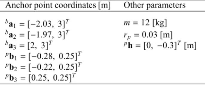
The rotation angle θ and the parasitic inclination θpare com-puted in this section along a given path for the design parame-ters given in Tab. 1 of the four-DoF planar cable-driven parallel
1https://drive.google.com/file/d/0B80GqJ5822jObDlXNkdOUWd6UUE/view?usp=sharing
Table 1: CDPR Parameters associated to the case.
Anchor point coordinates [m] Other parameters ba 1=[−2.03, 3]T m = 12 [kg] ba 2=[−1.97, 3]T rp =0.03 [m] ba 3=[2, 3]T ph = [0, −0.3]T [m] pb 1 =[−0.28, 0.25]T pb 2 =[−0.22, 0.25]T pb 3 =[0.25, 0.25]T
robot with a cable loop shown in Fig. 2. Eq. (33) expresses the Cartesian coordinates vector of seven via-points, namely, V1,...,V7, on the prescribed path (blue path in Fig. 2).
bv 1= −1 0 , bv2= −1 0.65 ,bv3= −0.65 +1 , bv4= 0 +1 bv 5= 0.65 +1 , bv6= +1 0.65 ,bv7= +1 0 (33) 7. Discussion
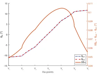
Figure 4 shows the natural inclinations θn1 and θn2 of the previous case study obtained with approaches 1 and 2 along the prescribed path, respectively. The difference between θn2 and θn1along the prescribed path is also depicted in Fig. 4. It appears that both approaches 1 and 2 give similar results, which confirms the soundness of the assumption made in approach 2. Figure 5 shows the rotation angle θm1 and θm2 of the moving-platform obtained with approaches 1 and 2, respectively, along the prescribed path, for δt = 20 N. Finally, Fig. 6 illustrates the parasitic inclination θpof the MP for different values of the ca-ble tension difference δt into the caca-ble-loop. It should be noted that θp increases with δt. This confirms the link between δt in the cable loop and the parasitic inclination of the MP.
Overall, the approach proposed in section 4.2 yields consis-tent results and can be applied to determine the parasitic incli-nation. Furthermore, this approach can be used to design the robot with respect to its parasitic inclination. This contributes to better control and more accurate positioning.
8. Conclusion
This paper introduced a four-DoF planar under-constrained cable-driven parallel robot. The robot utilizes a double-actuated cable loop system which grants an unlimited orienta-tion workspace for the end-effector. Nevertheless, the moving-platform undergoes some parasitic inclinations that are due to the presence of a cable loop. Moreover, an analytical method to find the orientation of the moving-platform is presented. This method is validated by comparing its results with the solution of geometrico-static equations of the robot. Then, an approach was established to isolate the parasitic inclination induced by cable loop only from the natural inclination of the moving-platform.
Some experimental validations will be conducted in the future to validate the theoretical results presented in this paper. The optimim design paramerers of the robot will be also searched
Saman Lessanibahri et al. / Procedia CIRP 70 (2018) 296–301 301
6 S. Lessanibahri et al. / Procedia CIRP 00 (2018) 000–000
V1 V2 V3 V4 V5 V6 V7 Via-points -15 -10 -5 0 5 10 15 θn [ o] -1.5 -1 -0.5 0 0.5 1 δθn = θn2 − θn 1 [ o] × 10-3 θ n1 θn2 δθ n
Fig. 4: Natural inclinations θn1and θn2of the moving-platform obtained with
Approaches 1 and 2 along a prescribed path
V1 V2 V3 V4 V5 V6 V7 Via-points -15 -10 -5 0 5 10 15 θm [ o] 0.04 0.05 0.06 0.07 0.08 0.09 0.1 0.11 δθm = θm 2 − θm 1 [ o] θ m1 θm2 δθm
Fig. 5: Rotation angle θm1and θm2of the moving-platform obtained with
Ap-proaches 1 and 2 for δt = 20 N.
V1 V2 V3 V4 V5 V6 V7 Via-points 0.05 0.1 0.15 0.2 0.25 0.3 0.35 0.4 θ p [ ] t = 5 N t = 1 0 N t = 1 5 N t = 2 0 N δ δ δ δ
Fig. 6: Parasitic inclination θpof the moving-platform for different values of
the cable tension difference δt into the cable-loop
for the parasitic inclinations of its articulated moving-platform to be a minimum.
References
[1] JA Carretero, RP Podhorodeski, MA Nahon, and Clement M Gosselin. Kinematic analysis and optimization of a new three degree-of-freedom spatial parallel manipulator. Journal of mechanical design, 122(1):17–24, 2000.
[2] Marco Carricato. Inverse geometrico-static problem of underconstrained cable-driven parallel robots with three cables. Journal of Mechanisms and
Robotics, 5(3):031002, 2013.
[3] Lorenzo Gagliardini, St´ephane Caro, Marc Gouttefarde, and Alexis Girin. Discrete reconfiguration planning for cable-driven parallel robots.
Mecha-nism and Machine Theory, 100:313–337, 2016.
[4] M John D Hayes and Robert G Langlois. Atlas motion platform: full-scale prototype. In CSME International Congress, 2012.
[5] M John D Hayes, Robert G Langlois, and Abraham Weiss. Atlas motion platform generalized kinematic model. Meccanica, 46(1):17–25, 2011. [6] Jean-Baptiste Izard, Marc Gouttefarde, Mica¨el Michelin, Olivier
Tem-pier, and Cedric Baradat. A reconfigurable robot for cable-driven parallel robotic research and industrial scenario proofing. In Cable-driven parallel
robots, pages 135–148. Springer, 2013.
[7] Sadao Kawamura, Hitoshi Kino, and Choe Won. High-speed manipulation by using parallel wire-driven robots. Robotica, 18(1):13–21, 2000. [8] Daniel Krebs, Gunnar Borchert, and Annika Raatz. Simulation and
de-sign of an orientation mechanism for assembly systems. Procedia CIRP, 44:245–250, 2016.
[9] Tam Nhat Le, Hiroki Dobashi, and Kiyoshi Nagai. Configuration of redun-dant drive wire mechanism using double actuator modules. ROBOMECH
Journal, 3(1):25, 2016.
[10] Tam Nhat Le, Hiroki Dobashi, and Kiyoshi Nagai. Kinematical and static force analysis on redundant drive wire mechanism with velocity constraint modules to reduce the number of actuators. ROBOMECH Journal, 3(1):22, 2016.
[11] Rongfu Lin, Weizhong Guo, and Feng Gao. On parasitic motion of parallel mechanisms. In ASME 2016 International Design Engineering Technical
Conferences and Computers and Information in Engineering Conference,
pages V05BT07A077–V05BT07A077. American Society of Mechanical Engineers, 2016.
[12] Kiyoshi Nagai, Tam Nhat Le, Yoshikatsu Hayashi, and Koji Ito. Kinemat-ical analysis of redundant drive wire mechanisms with velocity constraint. In Mechatronics and Automation (ICMA), 2012 International Conference
on, pages 1496–1501. IEEE, 2012.
[13] Dinh Quan Nguyen, Marc Gouttefarde, Olivier Company, and Francois Pierrot. On the analysis of large-dimension reconfigurable suspended cable-driven parallel robots. In Robotics and Automation (ICRA), 2014
IEEE International Conference on, pages 5728–5735. IEEE, 2014.
[14] Angelos Platis, Tahir Rasheed, Philippe Cardou, and St´ephane Caro. Isotropic design of the spherical wrist of a cable-driven parallel robot. In
Advances in Robot Kinematics 2016, pages 321–330. Springer, 2018.
[15] Giulio Rosati, Damiano Zanotto, and Sunil K Agrawal. On the design of adaptive cable-driven systems. Journal of mechanisms and robotics, 3(2):021004, 2011.
[16] Xiaoqiang Tang and Rui Yao. Dimensional design on the six-cable driven parallel manipulator of fast. Journal of Mechanical Design,