Zurich, Switzerland, June 6-8, 2012
DEVELOPMENT OF AN INTERFACE BETWEEN CFD AND FE
SOFTWARE
Nicola Tondini*, Olivier Vassart** and Jean-Marc Franssen*** * University of Trento, Italy
e-mail: [email protected] ** ArcelorMittal, Luxembourg e-mail: [email protected]
*** University of Liege e-mail: [email protected]
Keywords: CFD-FE interface, Weak coupling, Compartment fires.
Abstract. The paper presents the assumptions and the issues that arise when developing an integrated modelling methodology between a Computational Fluid Dynamics (CFD) software applied to compartment fires and a Finite Element (FE) software applied to structural systems subjected to fire. In particular, a weak coupling approach used to simulate a fire exposed structure by modelling the fire development in the compartment, the heat penetration in the structure and the mechanical response is described. The advantages and the disadvantages of such a technique are highlighted compared to a full coupling that conversely takes into account all mutual interactions. The favourable aspect of computing the thermal response of the structure in the FE model in order to avoid modelling the structure in the CFD model is underlined, namely a sensitive reduction of computational demand. Finally, a practical application is presented.
1 INTRODUCTION
Integrated modelling methodologies applied to compartment fires in order to obtain the thermo-mechanical response of structures exposed to fire would represent a powerful tool to widen the application field of structural fire safety engineering by overcoming limitations associated to simplified procedures. The exploitation of such strategies based on the coupling between CFD and FE programs are already used in medicine, e.g. for modelling the blood flow in arteries [1]. However, in the fire engineering field, very few applications are available and the ones that have been developed are often limited to specific software pairs [2]. The Research Fund of Coal and Steel (RFCS) project called FIRESTRUCT [3] dealt with this issue by studying different coupling approaches and employing different software. In this paper is described the weak coupling approach developed here between the CFD software Fire Dynamics Simulator (FDS) and the FE software SAFIR, but it has to be underlined that the methodology could be used with any CFD and any FE software. The study is illustrated by an application of this methodology about an experimental campaign dealing with the problem of columns engulfed in a fire source.
2 OVERVIEW ON INTEGRATED CFD-FE METHODOLOGY
2.1 Compartment fires: problem definition
Three problems have to be solved when modelling the behaviour of a structure subjected to a compartment fire, each of them being governed by different physical phenomenon and, hence, by different equations: 1) temperature development in the compartment; 2) thermal response of the structure and 3) mechanical response of the structure. The fire development analysis yields the temperatures of gasses and the radiative and mass flows in the compartment. By means of the thermal analysis, the temperatures in the structural elements are obtained. The mechanical response provides the behaviour of the structural system, i.e. stresses, deflections etc. Several differences distinguish these three processes. First, the spatial scale of the thermal analysis in the structure is an order of magnitude smaller than the spatial scale used for the compartment temperature development and the mechanical response. Second, the time scale may be different to solve the problem within CFD and FE. Third, for the temperature development in the compartment and the mechanical response a 3D analysis is generally required, whereas for the thermal analysis a 2D analysis is usually sufficient. Thus, some issues arise when an integrated methodology CFD-FE is to be used to tackle the whole problem. It is natural to assign the task of performing the compartment temperature development analysis to the CFD model and the mechanical response to the FE model, but it is not so straightforward to decide where to carry out the thermal analysis. Both software may be exploited to fulfil the task. The advantages to perform the thermal analysis in the CFD model are first to get direct information from the compartment temperature development analysis and, second, to allow consideration of the energy absorbed by the structure to be considered in the analysis of the compartment. On the other hand, if the thermal analysis in the structure is carried out in the FE model, all data necessary are directly available by the FE code to determine the mechanical response. Whatever the choice, the difficulties arise when data have to be exchanged between the two software, because of different scales in space and time. Moreover, if the thermal analysis is performed in CFD software, the compartment model must include the structure as well. The latter aspect is not desirable as described later on.
2.2 Levels of coupling
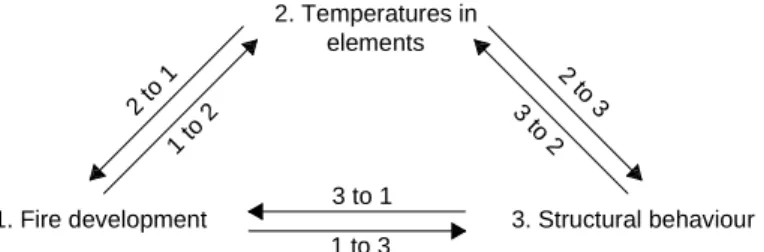
From the description of the problem it is clear that coupling CFD to FE model is far from straightforward and that the selected level of coupling influences the complexity of the model. In reality all three problems are mutually coupled (full coupling or two-way coupling) as shown in Fig. 1 and reported in Table 1, where the main phenomena involved in a compartment fire are listed along with their mutual interaction. 1. Fire development 2. Temperatures in elements 3. Structural behaviour 2 to 1 1 to 2 2 t o 3 3 t o 2 3 to 1 1 to 3
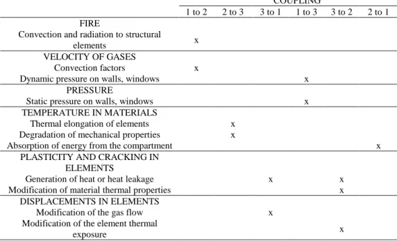
Table 1. Mutual interactions of main phenomena involved in a compartment fire COUPLING
1 to 2 2 to 3 3 to 1 1 to 3 3 to 2 2 to 1 FIRE
Convection and radiation to structural
elements x
VELOCITY OF GASES
Convection factors x
Dynamic pressure on walls, windows x
PRESSURE
Static pressure on walls, windows x
TEMPERATURE IN MATERIALS
Thermal elongation of elements x
Degradation of mechanical properties x
Absorption of energy from the compartment x
PLASTICITY AND CRACKING IN ELEMENTS
Generation of heat or heat leakage x x
Modification of material thermal properties x
DISPLACEMENTS IN ELEMENTS
Modification of the gas flow x
Modification of the element thermal
exposure x
The implementation of a full coupling allows taking into account all phenomena and it guarantees a general field of application as well as a solution that tends to be exact. An example of full coupling is the interface developed between VESTA, a CFD software, and DIANA, an FE software developed by TNO in the Netherlands [3]. However, an integrated methodology that relies on full coupling is very complex to achieve. The first reason lies in various uncertainties that question the so-called exactness of the method. For instance, heat leakage through cracks in concrete or gypsum plaster boards enclosures are still very difficult to quantify because they do not follow deterministic rules. Moreover, from a programming point of view, the code of the selected CFD software and the code of the FE program have to be modified so that they can communicate for the exchange of data, but it means that in most cases the integrated methodology will not work if another CFD or another FE software is used. This is a clear drawback in terms of versatility and flexibility. Furthermore, for each simulation, a CFD specialist as well as an FE specialist are required since the two models cannot be run independently. Other typical issues that may occur in the design practice are related to possible modifications that the structure undergoes during the construction project as well as modifications of the structure that have to be applied because of an unsatisfactory behaviour in terms of fire safety requirements. Since the structural elements must be included in the CFD model, any changes in the structural system imply that the whole analysis must be re-run, entailing large time consuming analyses.
From these considerations, a simplified approach, the so-called weak coupling, is proposed to overcome the major aforementioned issues with the aim to be applicable to a wide number of likely-to-occur scenarios in compartment fires.
3 PROPOSED WEAK COUPLING METHODOLOGY
3.1 Assumptions and general remarks
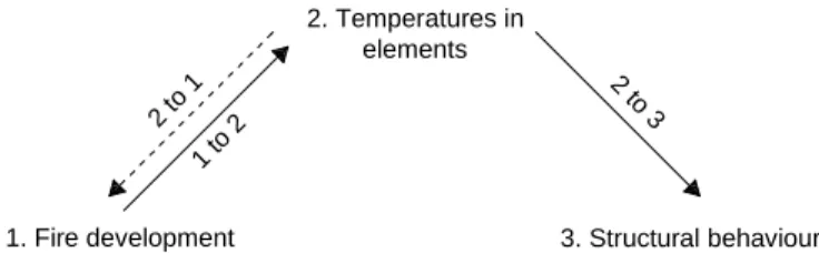
In the proposed weak coupling (or one-way) approach the mutual interactions are discarded, as illustrated in Fig. 2. The CFD software models the fire development, while the FE program performs the thermal and the mechanical analyses. The fire development is calculated independently of the thermal response in the linear elements of the structure such as, for example, steel columns, beams or truss girder. If part of the structure is made of planar elements that also constitute boundaries of the compartment such as, for example, concrete walls or slabs, they must be modelled, perhaps with some degrees of approximation [4], in the fire development analysis. The detailed temperature field in these structural elements will nevertheless be computed subsequently by the FE software. As a consequence, if m variations of the structure must be evaluated under n fire scenarios, only n CFD analyses have to be performed, compared to m·n coupled analyses in a full coupling approach.
In this strategy, the thermal response of the structure represents the input of the mechanical analysis. Hence, it can be performed first, over the whole time domain, and then the resulting data are transferred at the beginning of the mechanical analysis which is performed subsequently.
1. Fire development 2. Temperatures in elements 3. Structural behaviour 1 to 2 2 to 3 2 to 1
Figure 2. Weak coupling strategy between the main phenomena involved in a compartment fire Nonetheless, these simplifications imply some limitations:
i) the dimensions of the structural elements and their displacements perpendicular to their longitudinal axis must be small compared to the dimensions of the compartment in order not to significantly influence the temperatures and the air flow around the elements. For instance, a 1x1 m² concrete columns in a 100 m2 compartment must clearly be considered in the CFD model. This would also be the case for 1-meter deep concrete beams in a car park with a distance from the floor to the beams that is on the order of magnitude of 2 meters. Very flexible structures that are sensitive to air pressure variation are also not suitable for such integrated methodology because the effects of air pressure variation on the displacements of the structure cannot be neglected. Floor systems designed according to the tensile membrane action also exhibit very large displacements during the fire and may also not comply with this requirement if the floor to ceiling distance is small compared to the displacement.
ii) It is possible, for each 2D thermal analysis, to consider the boundary conditions at the surface of the section at the same point, namely the point of the section located on the node line of the beam element, for example at the centre of gravity of the section. The influence of the distance from the node line of the section to the border of the section is neglected. This is consistent with the fact that the structure is not present in the CFD analysis because the size of the section perpendicular to the longitudinal axis is negligible with respect to the size of the compartment; the distance from the centre of the section to the border (approximately ½ of the size of the section) is then also negligible.
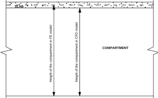
iii) Generally, in the CFD model the dimensions of a parallelipedic compartment correspond to the clear distances between opposite walls. However, in the FE model a slab is modelled in correspondence to its centreline as illustrated in Fig. 3. Thus, the slab would fall outside the CFD domain and assumptions have to be made in order to determine thermal information at the slab centreline.
H e ig h t o f th e c o m p a rt m e n t in C F D m o d e l H e ig h t o f th e c o m p a rt m e n t in F E m o d e l SLAB COMPARTMENT
Figure 3. Different compartment dimensions for the CFD and the FE model.
iv) Since the structure is not included in the CFD model, the effect of shielding from any structural elements on others cannot be detected. For example, if a series of closely-spaced columns one behind the other is impinged by a radiant flux with direction parallel to the column series, the magnitude of the flux received by each column will only depend on the distance of each single column from the fire source and no effects of shielding will be taken into account on the columns behind the first one.
v) Irrigated structures in which water is circulating in order to keep the temperature of the structure within acceptable limits cannot be neglected because they may contribute in evacuating important amount of energy from the compartment.
This procedure is thus particularly well adapted for metallic structures made of relatively thin members (frame, truss girders) and located in very large compartments (railway or airport entrance halls, exhibition halls) where a localised fire is developing and simplified thermal models, such as those proposed in EN1991-1-2 [5], cannot be employed because the geometry of the compartment is too complex or the position of the structure in the compartment or with respect to the position of the fire is not within the field of application of simplified model.
3.2 How it works
In this section, the practical issues that have to be solved when implementing such an approach are presented. The programs used in this paper to illustrate the proposed integrated methodology are FDS [6] and SAFIR [7]. The main steps needed to couple CFD and FE are:
1) at the end of the CFD analysis, a transfer file containing all information regarding the situation in the compartment, i.e. temperature of gas, convection factors and radiant intensities from various directions, is produced. These quantities can be provided at each grid point of the CFD model (the grid that was required to allow a precise determination of the solution) or instead at grid points of a coarser mesh reckoned by the CFD user as sufficient to get a sufficiently accurate representation of the solution that has been obtained. The mesh of considered points can also be refined around the structure that will be analysed and coarser away from the structure.
The format of the transfer file should be as standardised as possible so that in a future perspective it could be used for any choice of CFD and FE software. Hence, type of file (e.g. ASCII), syntax, type of reference system, type and format of numbers, presence of blank lines etc. have to be clearly stated. Such a format has been proposed within the FIRESTRUCT project and can be obtained from the authors. Radiant intensities from different direction are preferred to impinging radiant fluxes on predefined surfaces because the structural elements are not included in the CFD model and thus no information is available at that stage about the shape of the cross-sections. The fluxes at the surface of the structural elements will be computed within the FE software by integrating the radiant intensities which allows taking into account possible shadow effects in concave sections.
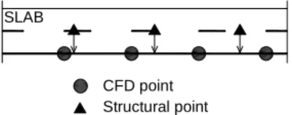
2) A 3D Cartesian spatial interpolation is needed because the points of the structure where the information is needed (called here “the structural points”) generally do not coincide with the points of the CFD grid where the information is provided. If any structural points fall outside the CFD domain for the reason described above, they are moved to the closest boundary of the CFD domain where the Cartesian interpolation can be made (see Fig. 4). A trilinear interpolation algorithm was successfully implemented in SAFIR to fulfil the 3D Cartesian interpolation.
CFD point Structural point SLAB
Figure 4. Case of structural points outside the CFD domain
3) An interpolation in the time domain is also necessary because the time steps of the CFD analysis and the time steps of the thermal analysis may not be the same. In this case a simple linear interpolation may be used.
4) In order to get the impinging fluxes q on the surface of the structural elements a spherical numerical integration of radiant intensities I has to be performed. A numerical integration can be performed according to Eq 1. cos n q Ii i i i θ ϖ ∑ = (1)
where n is the number of intensities considered for the integration, ωi is the solid angle associated to the direction i and θi is the angle between the direction of the radiant intensity i and the normal to the surface.
The directions of the intensities which are required to perform the spherical integration are generally not the directions in which the intensities are given by the CFD analysis. This is particularly the case if the structural elements are not parallel to the axes of the system of coordinates used in the CFD analysis (e.g. for diagonals in a truss girder). A spherical interpolation is thus performed in order to obtain the radiant intensities in the directions required by the numerical integration. Rotations of local axes are required to find the surface system of coordinates taking into account the direction of the longitudinal axis and the shape of the cross-section.
It is essential that the type of mesh and type of system of coordinates used in the CFD analysis (step 1) be clearly defined and taken into account in steps 2 and 4. The format of the transfer file established within the FIRESTRUCT project is based on the hypotheses of a structured parallelipedic mesh in a dextrorsum Cartesian system of coordinates. The position of the origin of the system of coordinates and the directions of the “X”, “Y” and “Z” axes as well as the direction of gravity must be common in the CFD and in the FE analyses.
4 AN EXAMPLE OF PRACTICAL APPLICATION
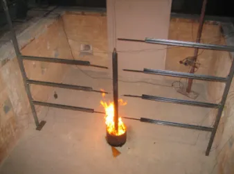
The authors are currently involved in a research project that deals with the problem of columns engulfed in a fire source and the assessment of the real effect of the emissivity of flames. For this purpose, two experimental tests with two types of combustible liquid are envisaged: i) a preliminary small scale test serving as a feasibility study; a 60.3 mm diameter, 1500 mm high circular tube is engulfed in a 300 mm diameter pool fire and ii) a 203 mm diameter, 3000 mm high circular tube engulfed in a 1000 mm diameter pool fire. In order to measure temperatures at different heights, an instrumentation set-up was designed. Fig. 5 shows the system designed for the larger pool fire while Fig. 6 shows the system used in the preliminary small-scale tests. Since the steel rack system used to support the bars where the
thermocouples are installed is slender and thermal information (temperatures, fluxes, etc) around the pool fire was not known, the described methodology was exploited to check whether the rack could undergo deformations that could affect the set-up configuration during the tests. Therefore, the pool fire of diameter 1 m was firstly simulated in FDS to get all information at the rack location. Then, the thermal analysis and the mechanical response of the rack modelled in SAFIR were carried out on the basis of the results provided by the CFD analysis. In detail, a kerosene pool fire, having a constant Rate of Heat Release (RHR) of 1634 kW/m2, was simulated without including the rack into the CFD model, as illustrated in Fig. 7. For symmetry reasons, only the space for one of the two racks was allowed for in the CFD model. At the end of the simulation the transfer file including all thermal information due to the pool fire was created.
x y z y x z x y z 3 0 0 0 6 0 4 1 3 0 1 0 6108 3 0 0 0 1534 Ø10 00 1534 6 9 3 1 6 9 3 2 6 9 3 3 6 9 3 4 6 9 3 A B C D x y z 3 0 4 1
Figure 5. Instrumentation set-up for a pool fire of diameter 1 m in which a column 3 m high and of diameter of 203 mm is placed (dimensions in mm).
Figure 6. Instrumentation set-up used to measure temperatures at different heights of a pool fire of diameter of 300 mm which engulfs a steel circular column 1500 mm high and of diameter 60.3 mm.
Figure 7. Pool fire modelled in FDS.
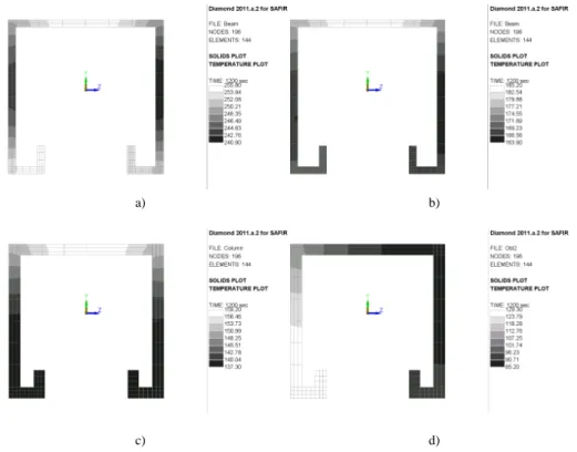
The rack was modelled in SAFIR by means of Bernoulli-type 3D beam elements. A 2D thermal analysis was thus performed at each of the longitudinal point of integration in the beam elements. In Fig. 8 the temperature distribution in the sections located as indicated by a cross in Fig. 5 is reported. The local axes of each beam element are also depicted in Fig. 5 to show the orientation. From Fig. 8 the effect of the non-uniform radiation affecting the sides of the sections is clearly visible and a coherent temperature distribution in the section on the basis of the orientation of the element with respect to the fire location is highlighted. Finally, the results of the thermal analysis were used to calculate the mechanical response of the rack; the calculated displacements are shown in Fig. 9, amplified by a factor of 20.
This simple case highlights the usefulness and the versatility as well as the capability of this integrated methodology to overcome problems that cannot be analysed by simplified models.
a) b)
c) d)
Figure 8. Temperature distribution at 1200 s in: a) beam section A; b) beam section B; c) column section C; d) bracing section D.
a) b)
5 CONCLUSION
This paper describes assumptions and issues of an integrated modelling methodology for the behaviour of a structure located in a fire compartment by implementing a weak coupling approach. This strategy allows performing the fire development analysis independently from the thermal analysis of the structure and from the mechanical response analysis by neglecting the structural elements in the CFD model. Hence, it is suitable for localised fires in very large compartments built with relatively thin structures where the transverse dimensions of the structural elements can be neglected. The existence of a standardised transfer file used to communicate the data between the CFD and the FE software is fundamental to guarantee versatility of the strategy. Finally, a practical application showed the usefulness and the capability of the methodology.
REFERENCES
[1] Zhao S. Z., Xu X. Y. and Collins M. W., The numerical analysis of fluid–solid interactions for blood flow in arterial structures Part 2: development of coupled fluid–solid algorithms, Proceedings of the Institution of Mechanical Engineers, Part H: Journal of Engineering in Medicine, 212: 241, 1998.
[2] Fellinger J. H. H, Kenyon Y. M., Breunese A. J. and Lemaire A. D., A coupled CFD-FEA study of a tunnel structure exposed to a fire, INTERFLAM, 10: 1349–1360, 2004
[3] Kumar S., Miles S. Welch S., Vassart O., Zhao B., Lemaire A.D., Noordijk L. M., Fellinger J. H. H. and Franssen, J.-M., FIRESTRUC – Integrating advanced three-dimensional modelling methodologies for predicting thermo-mechanical behaviour of steel and composite structures subjected to natural fires, RFCS project RFS-PR-02110, European Commission report, 2008. [4] Cooper L., Franssen J.-M., A Basis for Using Fire Modeling with 1-D Thermal Analyses of
Partitions to Simulate 2-D and 3-D Structural Performance in Real Fires, Fire Safety Journal, Vol. 33, 115-128, http://hdl.handle.net/2268/38130, 1999.
[5] CEN, Eurocode 1 : Actions on structures – Part 1-2 : General actions – Actions on structures exposed to fire, Bruxelles, 2004.
[6] McGrattan K. et al., Fire Dynamics Simulator (Version 5) - Technical Reference Guide, NIST Special Publication 1018-15, National Institute of Standards and Technology, Gaithersburg, MD, 2007.
[7] Franssen J.-M., SAFIR. A Thermal/Structural Program Modelling Structures under Fire, Engineering Journal, A.I.S.C., Vol 42, No. 3 , 143-158, 2005.