Edited by L. Arnold, H. Le Coroller & J. Surdej
PIONIER : A Four Telescope VLTI Instrument
B. Lazareff1 , J.-B. Le Bouquin1 , J.-P. Berger2 , G. Zins1 , P. Haguenauer3 , P. Gitton3 , A. Delboulbe1 , P. Feautrier1 , L. Jocou1 , P. Kern1 , Y. Magnard1 , T. Moulin1 , S. Rochat1 , E. Stadler1 , P. Labeye4 , M. Benisty1 , J. Kluska1 , K. Perraut1 , J. Knudstrup2 , J.-L. Lizon2 , R. Millan-Gabet5 , W. Traub6 , O. Absil7 1
UJF-Grenoble 1 / CNRS-INSU, Institut de Plan´etologie et
d’Astrophysique de Grenoble (IPAG), UMR 5274, Grenoble, France 2
European Southern Observatory, Karl-Schwarzschild-Str. 2, 85748 Garching bei M¨unchen, Germany
3
European Southern Observatory, Casilla 19001, Santiago 19, Chile 4
CEA-LETI, MINATEC Campus, 17 rue des Martyrs, 38054 Grenoble Cedex 9, France
5
NASA Exoplanet Science Institute (NExScI), California Institute of Technology, Pasadena, California, USA
6
Jet Propulsion Laboratory, California Institute of Technology, Pasadena, California, USA
7
Institut d’Astrophysique et de G´eophysique de Li`ege (IAGL), University of Li`ege, 4000 Sart Tilman, Belgium
Abstract. Pionier is a guest instrument, the first four-telescope recombiner at ESO’s VLTI. We discuss salient design features and illustrate selected scientific results from the first 21
2 years of operation.
1. Introduction
In 2009, optical long baseline interferometry started to produce images at milli-arcsecond (mas) scale, but the sensitivity limited its scope to stellar physics. The game was essentially dominated by CHARA. The VLTI, with its four 1.8m aux-iliary telescope, was ramping up in performance but was limited to a maximum of three-telescope recombiner (AMBER). The second-generation instruments, de-signed for four-telescope operation, were not due before 2014-2015 (GRAVITY, MATISSE).
IPAG was since long interested in developing aperture synthesis imaging for the observation of pre-main sequence environments. The IONIC intergrated
2. Instrument description
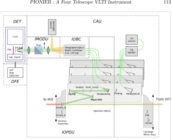
In this section we describe the main features of Pionier. More detailed descrip-tions can be found in Berger et al. (2010) and Le Bouquin et al. (2011). The subsystems of Pionier are shown on Figure 1.
2.1 Injection and calibration
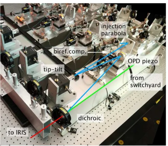
Each of the four beams from the VLTI enters the figure from the right, and is reflected off a dichroic mirror that, if observing in H band, transmits the K band to the IRIS guiding camera. It is then reflected off two plane mirrors in succession. The first one sits on a piezo-electric translation stage, and is used to modulate the optical path (OP) with an amplitude of 400µm. The second, also piezo actuated, is a a tip-tilt used in two ways: (a) align the instrument with the VLTI reference during startup; (b) dynamically respond to the focal plane offsets measured by IRIS. A shutter permits to selectively block each beam. A birefringence compensation device will be discussed in more detail further down. An off-axis parabolic mirror injects the signal into a single-mode fiber, that guides it to the input of the combiner. The four fibers have been carefully matched, not for group delay (which can easily be compensated with the OP piezo), but for dispersion. This is necessary to preserve good fringe contrast near zero OPD. This part of the system is shown on Figure 2.
2.2 Birefringence compensation
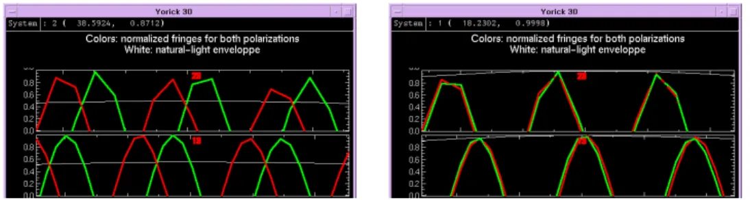
We now return, in more detail, to birefringence compensation. Astronomical sources are at most weakly polarized. And for natural light, orthogonal polariza-tions do not interfere. Therefore, it is important to maintain the orientation of the axes up to the IOBC input. In Pionier, this is ensured by using polarization maintaining fibers. By nature, such fibers are strongly birefringent, accumulat-ing one turn of differential phase over a few cm. Despite the careful (dispersion) matching of the fibers, the differential (between telescopes) birefringence is mea-sured to be typically a few fringes. The initial design included a Wollaston prism, to detect separately the fringes in the two orthogonal linear polarizations. To gain in signal-to-noise and in readout speed, birefringence compensation has been im-plemented. A birefringent plate of LiNbO3 is placed in each collimated beam. By changing the inclination of the plate, the phase delay between the two linear polarizations can be adjusted. This adjustment takes place with a Wollaston prism before the detector, allowing one to observe the fringes from the two po-larizations. See Figure 3. Once the two polarizations are aligned in group and phase delay, the Wollaston is removed. Twice more light per pixel and half the
Figure 1.: System diagram of Pionier. The subsystems are identified as follows. IOPDU: Injection Optics and Delay Unit; CAU: Calibration and Alignment Unit; IOBC: Integrated Optics Beam Combiner; IMODU: Imaging Optics and Disper-sion Unit; DET: Detector; DFE: Detector Frontend Electronics.
number of pixels to be read improves the S/N and allows to better freeze the turbulence. For more details, see Lazareff et al. (2012).
2.3 Integrated optics beam combiner
The integrated optics beam combiner (IOBC, Benisty et al. 2009) realizes the crucial function of interferometric recombination in optical waveguides imple-mented in silicon dioxide, where subsurface ion implantation permits a local in-crease of the refractive index. See Figure 4. The integration in silicon dioxide of the critical interferometric recombination is a guarantee of stability where it matters most: between the input of the beam splitters and the output of the recombiners. The IOBC has actually been fabricated in two major variants. In the first one, named AC, for each baseline, the two inputs generate two outputs A = (e1+ e2)/
√
2 and C = (e1− e2)/ √
2. The second one, named ABCD, gener-ates also: B = (e1+ ie2)/
√
2 and D = (e1− ie2)/ √
2. On the balance of pros and cons, the ABCD variant is used the most, allowing a measurement of the bias power underlying (in frequency space) the fringe power, and a robust, unbiased, visibility estimate. The major part of the observing is made in H band, but a K band IOBC is available in selected periods.
Figure 2.: A view of the four optical assemblies, implementing the functions of the IOPDU and CAU. The light path from input to the injection parabola is also shown
2.4 Dispersion
Prisms on a motorized stage between the IOBC and the camera provide, in ad-dition to the broadband (1.55-1.80µm) mode, two dispersion modes: ”small”, R ≈ 20 (3 channels), and ”large”, R ≈ 40 (7 channels). When the source flux is large enough that one can afford to disperse it (up to H=7 under good con-ditions), and the coherence time large enough to spend the time to read more pixels, this has two benefits: (a) spectral information, e.g. dust envelope versus star; (b) improved coverage of the UV plane.
2.5 Acquisition and data processing
The 12 (AC version) or 24 (ABCD) outputs of the IOBC are imaged on the detector, a Rockwell mercury-cadmium-telluride PICNIC array. The fringes are produced by temporal modulation of the OPD, sweeping the four OP piezo stages at rates −3s, −s, +s, +3s, such that the OPD on any baseline is swept at rates between 2s and 6s. We make use of the non-destructive readout of this detector in the so-called Fowler (default) mode. In a typical scan of 1024 steps (lasting
Figure 3.: Cancellation of the differential birefringence by adjusting the LiNbO3 plates, with the Wollaston prism inserted. Left: fringes from the two linear po-larizations are mis-aligned. Right: after alignment is completed. The Wollaston can then be removed for observing, without loss of fringe contrast.
700ms), the detector is read at each step, and is reset at the end of each scan. The capacity of the detector sites (≈ 105
electrons) makes this unsuitable for very bright objects (H≤4.5), for which we fall back to a reset-read-read sequence at each scan step.
The fringes are displayed in real-time, both in delay and frequency space. The raw data are processed in two steps: reduction, that produces raw visibil-ities and closures, and calibration. A quick-look pipeline is running during the observations, providing instant (a few minutes latency) feedback to the observer. Special attention has been paid in the data reduction software (DRS) to cope with changing atmospheric conditions, that affect the width of the fringes in fre-quency space, and to obtain an unbiased estimate of the underlying ”dark” level in frequency space. A detailed discussion of the DRS exceeds the scope of this report.
3. Operation and performance
Maybe the first question that a would-be observer will ask is: what is the magni-tude limit? The answer: it depends. To illustrate the intrinsic capabilities of Pi-onier, we show fringes and calibrated visibilities obtained for HD143006 (H=7.7) during the mother of all nights (coherence time >10ms). See Fig. 5. Without spectral dispersion, the limiting magnitude under good weather conditions can exceed H 8.
Observing conditions can degrade below ideal in two ways; seeing decreases the flux coupled into the fiber, and atmospheric piston broadens (in frequency space) the fringes. This is illustrated in Fig. 6. The real-time display of fringes helps the observer to make the right choice of: scan length (integration time), dispersion mode, and targets suited to prevailing conditions.
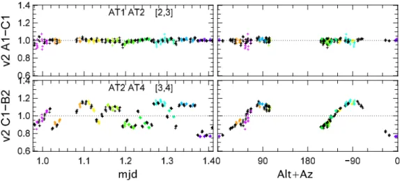
In some scientific programs, the accuracy of the Pionier data is limited not so much by the statistics of photons and of atmospheric phase, but by systematic effects. During the Exozodi program, aimed at the detection of faint debris disks, it was noted that calibrator visibilities had an anomalous scatter on baselines involving AT4. The results started to make sense when visibilities were plotted versus AZ +Alt, and can be explained by variable (with pointing) birefringence in the AT4 mirror train, with associated loss of visibility. See Fig. 7. In contrast with the Pionier internal birefringence, that effect is varying with telescope pointing.
Figure 4.: The integrated optics beam combiner (IOBC); three identical units on the same fabrication chip. Specular reflection lighting reveals the optical waveg-uides that reside below the surface. The light from the four telescopes is coupled at the left into the waveguides, each signal is split in three to interfere with the other beams, in the six possible baselines. With a proper design, the waveguides can cross their paths like railway tracks. For each baseline, a coupler (roughly 3/4 to the right) produces from its two inputs the outputs A = (e1+ e2)/
√ 2 and C = (e1− e2)/
√
2, for a total of 12 outputs.
The remedy so far has been to insist on calibrators being within 3◦of each science target (1◦ if possible).
4. Scientific results
The sensitivity, precision, and efficient coverage of the UV plane by Pionier have enabled scientific programs that were previously excessively time-consuming or just not possible. We select as an example the Herbig AeBe large program. In 30 nights, 50 objects were observed (most in the three VLTI/AT configurations), of which about 30 are clearly resolved, and a handful allow imaging. As an illustration, we show (Fig. 8) the data obtained for HD100546, and two com-pletely independent image reconstructions (Fig. 9) for the dusty environment of HD45677.
A broader view is provided in Fig. 10, showing in matrix form the perfor-mance requirements of some of the core science projects of Pionier, and how well they have been fulfilled by the as-built instrument. All programs, with the exception of the search for hot Jupiters, could be carried out in a productive way.
5. Status - Lessons learned
Since the commissioning of Pionier, several enhancements have been imple-mented:
Figure 5.: Left: fringes from a H=7.7 source during a very good night; only three of the six baselines shown to keep figure compact. Right: calibrated visibilities obtained during that night, color-coded according to the spectral channels.
Figure 6.: Statistical errors on visibilities and closures, versus flux per fringe (detector units), all observations of year 2012. Blue: 7-channel dispersion; green 3-channel; red: undispersed. At any abscissa, the vertical dispersion results from variations in the coherence time; the bottom envelope of the diagram represent-ing the degradation of S/N versus flux. Flux itself results from both the source magnitude and the seeing; the upper scale is for median seeing conditions.
– Motorize the disperser change, allowing remote operation – Implement K band
– Identify and eliminate instrument and reduction software systematics – Upgrade to RAPID camera with APD detectors - pending
The most significant limitations on the performance are: – Phase piston, from atmosphere (and also the telescopes) – Coupling loss from atmospheric seeing
– Calibration accuracy including telescope birefringence The lessons learned:
– Enabling technology (IOBC, 10 yrs of R&D) was a key factor – Keep It Simple
brations) References
Benisty, M., et al. 2009, An integrated optics beam combiner for the second generation VLTI instruments, A&A, 498:601-613
Berger, J.-P., et al. 2010, PIONIER: a visitor instrument for VLTI. In Society of Photo-Optical Instrumentation Engineers (SPIE) Conference Series, vol. 7734 of Society of Photo-Optical Instrumentation Engineers (SPIE) Con-ference Series
Lazareff, B., et al. 2012, A novel technique to control differential birefringence in optical interferometers. Demonstration on the PIONIER-VLTI instru-ment, A&A, 543:A31
Le Bouquin, J.-B., et al. 2011, PIONIER: a 4-telescope visitor instrument at VLTI, A&A, 535:A67
Figure 7.: Visibilities of calibrators on two baselines, one behaving normally, and another with an anomalous scatter. On the right pane, the values plotted versus AZ + Alt show a telltale cosine pattern.
Figure 8.: Observations of HD100546: UV coverage, visibilities, and phase clo-sures. The data contain a wealth of information: size, radial distribution, and anisotropy of the dust distribution around this Be9 star; e.g. the spread of visi-bilities vs spectral channel readily indicates the dust temperature, and the phase closures indicate a departure from centrosymmetry.
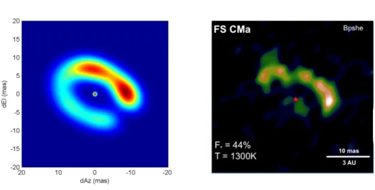
Figure 9.: Two independent images of HD45677/FSCma from the HAeBe large program. Left: parametric image fitting; right: Mira image reconstruction.
Figure 10.: Performance requirements for some of the projects that constituted the science case for Pionier. For each project, significant requirements are coded as follows. Green: fully met; orange: requires attention; red: problematic.