HAL Id: hal-00639700
https://hal.inria.fr/hal-00639700
Submitted on 9 Nov 2011
HAL is a multi-disciplinary open access
archive for the deposit and dissemination of
sci-entific research documents, whether they are
pub-lished or not. The documents may come from
teaching and research institutions in France or
abroad, or from public or private research centers.
L’archive ouverte pluridisciplinaire HAL, est
destinée au dépôt et à la diffusion de documents
scientifiques de niveau recherche, publiés ou non,
émanant des établissements d’enseignement et de
recherche français ou étrangers, des laboratoires
publics ou privés.
Evaluation of Model based Tracking with TrakMark
Dataset
A. Petit, Guillaume Caron, H. Uchiyama, E. Marchand
To cite this version:
A. Petit, Guillaume Caron, H. Uchiyama, E. Marchand. Evaluation of Model based Tracking with
TrakMark Dataset. 2nd Int. Workshop on AR/MR Registration, Tracking and Benchmarking, 2011,
Basel, Switzerland, Switzerland. �hal-00639700�
Evaluation of Model based Tracking with TrakMark Dataset
Antoine Petit∗ Guillaume Caron† Hideaki Uchiyama‡ Eric Marchand§
IRISA/INRIA Rennes
ABSTRACT
We benchmark two tracking methods developed in the INRIA La-gadic team with a TrakMark dataset. Since these methods are based on a 3D model based approach, we selected a dataset named “Con-ference Venue Package 01” that includes a 3D textured model of a scene. For the evaluation. we compute the error of 3D rotation and translation with the ground truth transformation matrix. Through these evaluations, we confirmed that the provided dataset was suit-able for quantitative evaluations of 3D visual tracking.
Index Terms: I.4.8 [IMAGE PROCESSING AND COMPUTER
VISION]: Scene Analysis—Tracking; H.5.1 [ INFORMATION IN-TERFACES AND PRESENTATION (e.g., HCI)]: Multimedia In-formation Systems—Artificial, augmented, and virtual realities
1 INTRODUCTION
This paper is related to the benchmarking process of tracking algo-rithm suitable for augmented reality applications. Although real-time tracking and registration methods received much interest in the last few years, this is still a key feature and, unfortunately, one of the bottleneck for the development of augmented reality based applications. Benchmarking such algorithms is then a necessary process to assess the efficiency of the proposed methods.
Whereas benchmarking keypoint detectors and trackers received much interest in the literature [13], few tentatives have proposed to benchmark and allowed a fair comparison of tracking algorithms. Among the few existing proposals, one can consider the Metaio benchmark [11] and the TrakMark benchmark. The former one, which is very demanding, mainly focuses on the evaluation of 2D template-based tracking algorithms. Considered approaches are keypoint matching methods (such as FERNS [14], SIFT [12] or SURF [3]) or tracking approach based the minimization of the SSD (such as the ESM [4]). Other approach which maximized the mu-tual information shared by two images [8] can also be considered. The latter allows evaluation on both real scene and real image, and can also be considered model-based tracking approaches. In both cases, ground-truth are available which allows fair comparisons and qualitative evaluation of proposed approaches.
In this paper, we propose to benchmark two model-based track-ing approaches developed in the INRIA Lagadic team [1]. The former is an extension to model-based 3D pose estimation [7] of mutual-information based tracker proposed in [8]. The second one, derived from [6, 17], is an edge-based registration process than take advantage of GPU rendering capability. Both approaches are based on the virtual visual servoing framework proposed in [6]. Virtual visual servoing is a formulation of a full-scale non-linear minimiza-tion based on the visual servoing scheme [5]. It established a dual-ity between vision-based robot control and various computer vision problem such as pose estimation, calibration, motion estimation,
∗e-mail:[email protected]
†e-mail:[email protected] ‡e-mail:[email protected] §e-mail:[email protected]
etc. Since these are model-based tracking method, we consider the TrakMark benchmark with the same sequence for which ground-truth is available. Evaluation criterion are also discussed.
2 DATASET
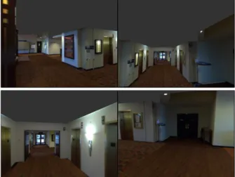
In the TrakMark datasets, many kinds of image sequences are pro-vided. We evaluated our tracking methods with one of the datasets named “Conference Venue Package 01”. This dataset includes the 3D textured model of the ISMAR2009 conference venue generated by Ishkawa et al. [10] and the computer-generated images with sev-eral camera motions. Especially, we selected the image sequence captured with parallel translation, panning and tilting of a cam-era because it was the most challenging motion of this TrakMark dataset for the evaluation.
Figure 1: Example of images. The scene of “Conference Venue Package 01” was captured at the ISMAR2009 conference venue. The computer-generated images and the 3D textured model are pro-vided.
3 METHODS
In this section, we provide the short descriptions of our tracking methods. The details will be presented in the future conferences and journals.
3.1 Mutual information based Tracking
Model based pose estimation using vision has been tackled using various feature types. We propose here to introduce the mutual information feature for this problem. Mutual information (MI) is defined thanks to the entropy H of two images I and I∗and their joint entropy:
MI(I, I∗) = H(I) + H(I∗)− H(I,I∗) (1) MI has been used for registration works [15, 16] and more recently to track planes in image sequences [8]. In the latter work, a pla-nar region is detected or selected in the first image of a sequence
and defines the reference template of the plane to track. Then, for the following image of the sequence, a homography is incremen-tally computed to warp the template in the current image so that the mutual information shared by both reference and current image regions is maximal. This optimization process is done for each new image and the initial guess is the optimal warp for the previous im-age, since in tracking processes, the motion in images is assumed to be small for a short period of time. This feature has shown to be robust to noise, specular reflections and even to different modalities between the reference image and the current one.
We consider here an extension of [8] to the case of non planar model based pose estimation and tracking. This extension adapts the use of MI over SL(3) presented in [8] to the SE(3) space. It means that the parameters space is the full six 3D pose parameters (three translations and three rotations) whereas it was eight param-eters to estimate in the previous work: the relative pose between current and reference cameras and the plane parameters, all up to scale.
We, hence, need to reformulate the cost function. The goal is to perform the registration of the model with respect to the image and it can be formulated as the maximization of the mutual infor-mation shared between the input image I∗and the projection of the modelM . Ifγ are the intrinsic camera parameters (focal length and principal point) and r its pose, the pose estimation problem can be written as:
ˆr = arg max
r MI
(
I∗, Iγ(M ,r)). (2)
Image Iγ(M ,r) is resulting from the projection of the model M at given pose r. From a first order Taylor expansion of the mu-tual information function at the current pose r, the link between the variation of the mutual information feature and the pose variation is expressed. The increment to apply to the pose is then obtained using a Newton’s optimization like method.
To solve this function, a textured 3D model of the object to track is necessary and it has to be projected for each camera pose r. To generate images of the 3D model, we used OpenGL as a 3D ren-derer and more particularly the Ogre3D library [2]. OpenGL al-lows not only to generate photometric images but also depth im-ages. More precisely, we obtain an image where each pixel con-tains the Z coordinate of the 3D point projected in this pixel. This is particularly interesting since the Z of each visible point appears in the Jacobian linking mutual information and pose variations.
The algorithm presented in Figure 2 sums up all the processes of the mutual information based pose estimation and tracking ap-proach. I* ri=0 3D engine entropy joint entropy entropy gradients IZ I Z Jacobian computation pose increment ri+1
Figure 2: Synopsis of the mutual information pose estimation algo-rithm. The process loops until the mutual information betweenIand
I∗is stable.
3.2 Depth and Texture Edge based Tracking
The second approach considers the use of a complete surface model, which can be textured or untextured. The method aims at
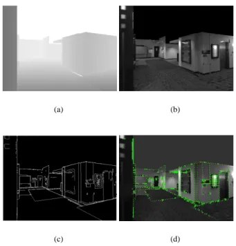
realigning edges generated from the rendered model and edges ex-tracted from the image by minimizing a criterion related to the error between these two kinds of edges. For this purpose, as in [17], at each acquired image, the model is rendered using hardwaaccelerated 3D graphics (GPU), through Ogre3D library, with re-spect to the pose computed for the previous image. The challenge is then to sort out visible and prominent edges from the rendered scene. We propose to determine these edges by combining informa-tion provided by both the depth buffer, and the rendered textures of the scene. From the depth buffer (see Fig. 3(a)), which corresponds to the depth values of the scene according to the camera viewing direction at each pixel point, we can extract changes or discontinu-ities that suit the visible geometrical properties of the scene. This is performed by applying a second order differential operator to the depth values. We also extract edges from the textures (Fig. 3(b)) by processing a classical Canny edge algorithm. Given the edge map of the complete scene (Fig. 3(c)), we can compute the 3D world coordinates of the edge points in the scene and so generate a 3D edge model, as we know the pose used for the projection and the depth of these points thanks to the z-buffer. As dealing with the whole edge map can be computationally heavy, we can sample it along i and j coordinates of the image in order to keep a reasonable number of these edge measurement points. From these points we need to find their corresponding edges in the image. In a similar manner to [17] and [6], we perform a 1D search along the normal of the underlying edge, whose orientation is retrieved thanks to So-bel filters computed on the grey level image of the normal map of the scene. As a matching edge point in the image, we choose the gradient maximum along the scan line (Fig. 3(d)).
(a) (b)
(c) (d)
Figure 3: On (a) and (b) are represented the z-buffer and the textures of the rendered 3D model using Ogre3D, from which the edge map is generated (c). This edge map is then sampled to extract measure-ment points, reprojected on the current image and from them a 1D search along the edge normal is performed to find a matching edge point in the acquired image (d).
Then, we compute the camera pose r which minimizes the errors between the projected edge measurement points pi(r) and the
cor-responding edge points p′iin the image. As the error we choose the distance between the projected 3D line Lpi(r) underlying pi(r) and
p′i. The criteria to minimize can be expressed as :
S =
∑
i
ρ(d⊥(Lpi(r), p′i)) (3)
where d⊥(Lpi(r), p′i) is the distance between a point p′iand the
cor-responding line Lpi(r), andρ is a robust estimator used to reject
outliers. The optimization technique is then similar to the virtual visual servoing framework described in [6].
4 EVALUATIONCRITERIA
In [11], the evaluation criterion was based on the reprojection error of four points located on the diagonal lines of a reference image. The ratio of tracked images against all input images was computed such that the number of tracked images was incremented when the reprojection error was less than a threshold. In the TrakMark datasets, some of them provide the ground truth of a 3× 4 trans-formation matrix from the world coordinate system to the camera coordinate system for all images. Therefore, we can evaluate the accuracy of rotation and translation components of a camera pose in 3D space.
The provided transformation matrix for each image is composed of a 3×3 rotation matrix R and a 3×1 translation vector t as [R|t]. We compute a rotation matrix Rcand a translation vector tcfor each
image and compared them with the ground truths as follows. For the rotation, the difference matrix Rdwith the ground truth rotation
matrix Rgis first computed:
Rd= RgRTc. (4)
The difference matrix is then decomposed into an axis and angle of rotation with Rodrigues’ rotation formula [9]. Because we use the angle as a difference of two rotation matrices, we compute the angle such that
θRd= arccos ( tr (Rd)− 1 2 ) . (5)
For the translation, the 2-norm distance (Euclidean distance) d with the ground truth translation vector tgis computed such that
d = tg− tc . (6)
Note that Huynh has reported that the best evaluation of 3D ro-tations was to use unit quaternions in [9]. However, we selected an angle component in the representation of rotation with an axis and angle as a criterion because it has more geometrical meaning.
5 EVALUATIONPROCEDURE
The whole procedure of our evaluation is as follows.
1. Download dataset images, intrinsic parameters and the ground truth of extrinsic parameters for each dataset image
2. Convert the format of the 3D model into Ogre 3D [2] for our codes
3. Set the ground truth of an initial image in the dataset to our tracking methods
4. Compute camera poses for the rest of the images
5. Compute the difference between our result and the ground truth with the evaluation criteria.
6 RESULTS
We evaluated our two tracking methods with the criteria and dis-cussed the results individually.
6.1 Mutual Information based Tracking
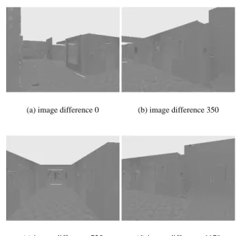
The nonlinear process of this method maximizes the mutual infor-mation, shared by the desired and current images, optimizing the pose of the virtual camera. It is not very clear to give mutual in-formation results. Thus, we chose to display image differences be-tween reference images from the dataset and images obtained at optimal poses computed thanks to our method. Image differences should be grey when both images are identical. Figure 4 shows some difference images at different locations along the trajectory. Since our virtual images are not rendered with the same 3D engine as the one used by TrakMark to obtain datasets, some rendering properties (texture filtering, colors, etc) may be different. That is why image differences are not perfectly grey at convergence. One can note that despite this problem, the registration succeeds. This is due to the mutual information feature which is robust to such is-sues, whereas more classical registration cost function, such as the sum of squared differences, are not.
(a) image difference 0 (b) image difference 350
(c) image difference 725 (d) image difference 1179
Figure 4: Qualitative evaluation of MI based pose estimation con-vergence. Difference between some reference images and images generated at optimal estimated pose.
After having evaluated results qualitatively in images, the evalu-ation of estimevalu-ations is done quantitatively in 3D. Figure 5 shows the estimated trajectory which is extremely close to the ground truth. This nearly perfect superimposition of both trajectories was clearly waited from the qualitative evaluation part (Fig.4) since if desired and current images are perfectly aligned, it means the pose of the virtual camera is quasi identical to the desired one.
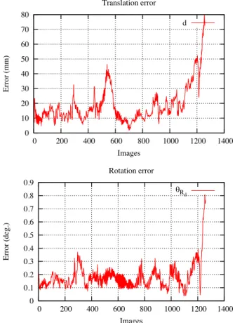
Estimations are also evaluated on the translational and on the rotational parts of each pose (Fig. 6).
6.2 Depth and Texture Edge based Tracking
For this method, we propose the comparison of the results of two approaches, one for which the generation of the edge map from the rendered model only relies on depth discontinuities, which are re-lated to the geometrical properties of the scene, and the other for which this generation process is based on both texture and depth discontinuities, as presented in Section 3.2. Fig. 7 and Fig. 8 qual-itatively show the performances of both approaches. The yellow
-4.5 -4 -3.5 -3 -2.5 -2 -1.5 -1 -0.5 0 -2-1 0 1 2 3 4 5 6 1.3 1.4 1.5 1.6 1.7 1.8 1.9 2 z(m) Trajectory Estimation Ground truth x(m) y(m) z(m)
Figure 5: Estimated trajectory using our mutual information based pose estimation (red) superimposed over the ground truth (blue).
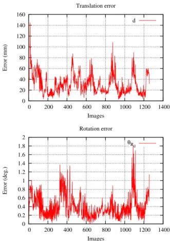
points represent the edge measurement points reprojected with re-spect to estimated camera pose. We observe that relying only on depth discontinuities is not really suitable for this very textured scene, as ambiguities between these depth edges and the textures edges in the image occur. This leads to some local minima, mak-ing the trackmak-ing fail. When includmak-ing the texture information, the tracking is properly performed throughout the whole sequence as seen on Fig. 8. For this approach, Fig. 9 shows the estimated tra-jectory which is very close to the ground truth and Fig. 10 shows the errors in terms of translation and rotation. This method is also quite computationally efficient as we reach a 13 frames per second for the first approach and 7 fps for the second.
7 CONCLUSION
We evaluated two visual tracking methods developed in the INRIA Lagadic team with a TrakMark dataset. One was an extension of 2D template based plane tracking with mutual information [8] to non-planar object tracking, and the other was based on the minimiza-tion of reprojecminimiza-tion error of 3D edges extracted from both texture and depth images. Since the ground truth provided in the dataset was the transformation matrix from the world coordinate system to the camera coordinate system, we use the error of 3D rotation and translation as evaluation criteria. Through the evaluations, we confirmed that the dataset was applicable to benchmarking visual tracking for both augmented reality and visual servoing.
REFERENCES
[1] Lagadic. www.irisa.fr/lagadic/.
[2] Ogre3D, open source 3D graphics engine. www.ogre3d.org. [3] H. Bay, A. Ess, T. Tuytelaars, and L. Van Gool. Speeded-up robust
fea-tures (SURF). Computer Vision and Image Understanding, 110:346– 359, 2008.
[4] S. Benhimane and E. Malis. Homography-based 2D visual tracking and servoing. International Journal of Robotics Research, 26:661– 676, 2007.
[5] F. Chaumette and S. Hutchinson. Visual servo control, Part I: Basic approaches. IEEE Robotics and Automation Magazine, 13(4):82–90, 2006.
[6] A. Comport, E. Marchand, M. Pressigout, and F. Chaumette. Real-time markerless tracking for augmented reality: the virtual visual ser-voing framework. IEEE Transactions on Visualization and Computer
Graphics, 12(4):615–628, 2006.
[7] A. Dame. A unified direct approach for visual servoing and visual
tracking using mutual information. PhD thesis, Universit´e de Rennes
1, 2010. 0 10 20 30 40 50 60 70 80 0 200 400 600 800 1000 1200 1400 Error (mm) Images Translation error d 0 0.1 0.2 0.3 0.4 0.5 0.6 0.7 0.8 0.9 0 200 400 600 800 1000 1200 1400 Error (deg.) Images Rotation error eR d
Figure 6: Estimation errors in (a) position and in (b) orientation over all the sequence, with respect to the ground truth.
[8] A. Dame and E. Marchand. Accurate real-time tracking using mutual information. In IEEE International Symposium on Mixed and
Aug-mented Reality Mixed Reality, pages 47–56, 2010.
[9] D. Q. Huynh. Metrics for 3D rotations: Comparison and analysis.
Journal of Mathematical Imaging and Vision, 35:155–164, 2009.
[10] T. Ishikawa, K. Thangamani, M. Kourogi, A. P. Gee, W. Mayol-Cuevas, K. Jung, and T. Kurata. In-situ 3D indoor modeler with a camera and self-contained sensors. In International Conference on
Virtual and Mixed Reality, pages 454–464, 2009.
[11] S. Lieberknecht, S. Benhimane, P. Meier, and N. Navab. Benchmark-ing template-based trackBenchmark-ing algorithms. Virtual Reality, 15:99–108, 2011.
[12] D. G. Lowe. Distinctive image features from scale-invariant key-points. International Journal of Computer Vision, 60:91–110, 2004. [13] K. Mikolajczyk and C. Schmid. A performance evaluation of local
descriptors. IEEE Transactions on Pattern Analysis and Machine
In-telligence, 27:1615–1630, 2005.
[14] M. Ozuysal, M. Calonder, V. Lepetit, and P. Fua. Fast keypoint recog-nition using random ferns. IEEE Transactions on Pattern Analysis and
Machine Intelligence, 32:448–461, 2010.
[15] C. Studholme, D. Hill, and D. Hawkes. An overlap invariant entropy measure of 3D medical image alignment. In Pattern Recognition, vol-ume 32, pages 71–86, 1999.
[16] P. A. Viola and W. M. W. III. Alignment by maximization of mutual information. International Journal of Computer Vision, 24(2):137– 154, 1997.
[17] H. Wuest and D. Stricker. Tracking of industrial objects by using CAD models. Journal of Virtual Reality and Broadcasting, 4(1), 2007.
(a) Image 4 (b) Image 144
(c) Image 260 (d) Image 315
Figure 7: Tracking relying on depth edges. Until (c), the tracking is properly performed, but then the ambiguities between geometrical and textures edges appears, and lead to local minima (d).
(a) Image 0 (b) Image 500
(c) Image 900 (d) Image 1257
Figure 8: Tracking relying on depth and texture edges. The tracking is properly performed throughout the sequence.
-4.5 -4-3.5 -3 -2.5 -2 -1.5 -1 -0.5 0 -2-1 0 1 2 3 4 5 6 1.3 1.4 1.5 1.6 1.7 1.8 1.9 2 2.1 z(m) Trajectory Estimation Ground truth x(m) y(m) z(m)
Figure 9: Estimated trajectory using the depth and texture edge based pose estimation (red) superimposed over the ground truth (blue). 0 20 40 60 80 100 120 140 160 0 200 400 600 800 1000 1200 1400 Error (mm) Images Translation error d 0 0.2 0.4 0.6 0.8 1 1.2 1.4 1.6 1.8 2 0 200 400 600 800 1000 1200 1400 Error (deg.) Images Rotation error θRd
Figure 10: Estimation errors in (a) position and in (b) orientation over all the sequence, with respect to the ground truth, for the depth and texture edge based pose estimation.