HAL Id: hal-01589873
https://hal.univ-brest.fr/hal-01589873
Submitted on 19 Sep 2017
HAL is a multi-disciplinary open access
archive for the deposit and dissemination of
sci-entific research documents, whether they are
pub-lished or not. The documents may come from
teaching and research institutions in France or
abroad, or from public or private research centers.
L’archive ouverte pluridisciplinaire HAL, est
destinée au dépôt et à la diffusion de documents
scientifiques de niveau recherche, publiés ou non,
émanant des établissements d’enseignement et de
recherche français ou étrangers, des laboratoires
publics ou privés.
A UWB Antenna in direct breast contact for cancer
detection
Zahra Katbay, Saadou Al Mokdad, Sawsan Sadek, Marc Le Roy,
Mohamad-Raafat Lababidi, André Pérennec
To cite this version:
Zahra Katbay, Saadou Al Mokdad, Sawsan Sadek, Marc Le Roy, Mohamad-Raafat Lababidi, et al..
A UWB Antenna in direct breast contact for cancer detection. IEEE SENSET 2017 (International
Conference on Sensors, Networks, Smart and Emerging Technologies), Beirut, Lebanon, Sep 2017,
Beirut, Lebanon. pp.1-4. �hal-01589873�
A UWB Antenna in direct breast contact for cancer
detection
Z. Katbay1, 3, S. Al mokdad2, S. Sadek1
1 Lebanese University, University Institute of Technology
Saida, Lebanon
2 Lebanese University, Doctoral School of Sciences and
Technology Z_Katbay@hotmail.com Saadou-ali-Almokdad@hotmail.com SawsanSadek70@gmail.com
M. Le Roy3, R. Lababidi3, A. Perennec3 3 Lab-STICC, UMR CNRS 6285,
Université de Brest (UBO)-Ensta Bretagne, France Andre.Perennec@univ-brest.fr
Marc.LeRoy@univ-brest.fr Raafat.Lababidi@ensta-bretagne.fr
Abstract— In this paper, a Ultra-Wide-Band (UWB) antenna of
dimensions 3cm x 3cm, designed to be used in direct contact with the breast is presented. The breast phantom model, on which the antenna was designed, consists of four layers (skin, fat, glandular tissues and muscle with their specific thicknesses) taking into account the dielectric properties for each layer and their dependence versus frequency. The antenna has been optimized for many reasons: enhance the matching to the human body and maximize the transfer of energy into the breast phantom to increase the detection potential.
Keywords—UWB antenna; breast phantom.
I. INTRODUCTION
Imaging techniques and Ultra WideBand detection, typically in the 3.1-10.6 GHz band, are increasingly being studied and used for medical applications such as microwave imaging. Indeed, UWB techniques for cancer detection have several advantages: i) in the frequency band corresponding to these ultra-short radar pulses, a significant contrast appears between the relative dielectric permittivity and conductivity of healthy tissues and those of malignant tissues. (ii) These impulses provide, in theory, a sufficient penetration depth in the breast and a resolution of, at least, one centimeter. This range of UWB frequencies allows us to have simultaneously a good spatial resolution and a sufficient penetration depth for breast imaging. Antennas are one of the system’s key and their characteristics strongly impact the performance of the overall system.
Usually, the antenna is designed and matched in air, and then an immersion or coupling liquid [1], or even an air gap [2], are used to match the antenna into the human body, and to couple the maximum power and reduce reflections. Indeed, matching the antenna to the skin on the specified band is not sufficient to ensure a strong energy coupling in the human body because the high dielectric contrast at the interface air-skin introduces a strong reflection. In this paper we propose a compact broadband antenna with some improvements in order to use it in a direct contact with the human body in order to improve the transfer of the energy radiated by the antenna. In our work, the different layers of the breast phantom are modeled by using Debye models [3] in a wide operational frequency range from 2 to 10 GHz.
This paper is organized as follows: section II describes the antenna design, section III presents the improvements of the antenna for a direct contact with the breast model and to optimize the transfer of the energy in the phantom and finally, in section IV, some conclusions and perspectives are proposed.
II. ANTENNA DESIGN
The initial structure of the antenna consists of a rectangular patch printed on FR4 substrate with dielectric permittivity εr=4.4, thickness of 1.6 mm and loss tangent tan=0.02.
To increase the antenna bandwidth, modifications in the structure have been made. First, the full ground plane has been replaced by a partial ground plane [4] and its length Lg has been optimized (fig 1.b corresponding orange curve). Then, notches (fig 1.c, red curve) have been made on the main radiating element. The notches enhance the antenna response in the band 6.5 GHz-8.5 GHz. Finally, slots with optimized dimensions were made in the partial ground plane, the length L1 of these resonant slots are approximately a multiple of λ/4
at 9 GHz in order to improve the antenna response around this Frequency. The different configurations of this antenna are shown in Fig 1 as well as the simulation results in free space which show the successive improvement of the antenna response to finally obtain an ultra-wide band from 3.5 to 10.6 GHz. The optimized dimensions of the antenna in mm are summarized in Table 1.
TABLE I. ANTENNA DIMENSIONS
Wsub Lsub Wr Lr Wf Lf W1 L1 Lg
Fig. 1. (a)Antenna topologies with the modifications and (b) the corresponding simulation results in free space.
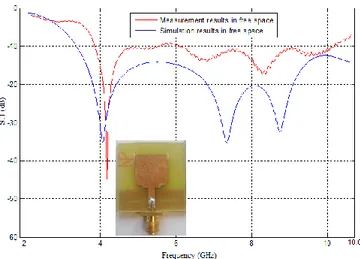
Fig. 2. Comparaison simulation / measurement results of the antenna (d).
The measurement results in free space are in good agreement with the simulation results; the antenna measured-bandwidth extends from 3.86 to 10.2 GHz as shown in fig 2.
III. ANTENNA OPTIMIZATION IN DIRECT CONTACT WITH THE BREAST PHANTOM
A. Breast phantom
To study the interaction between the designed antenna and the breast, a phantom model of the breast has been developed. This model is composed of four layers: the skin, the fat, the glandular tissues and the muscle. Many models still use constant dielectric properties (permittivity and conductivity) [5] - [6]. In our work, each layer has dielectric dispersive properties as defined in [7] between 2 to 10 GHz and an average specific thickness. Fig 3 shows this phantom model.
The frequency dependence in the band of interest of the dielectric constant ε (ω) and the conductivity σ (ω) has been modeled using the single-pole Debye dispersion equations:
( )
Where ω is the angular frequency, σS/ωε0 are the dielectric
losses as a function of the frequency, ε∞ is the relative
permittivity at very high frequencies, εs is the static relative
permittivity, σs is the static conductivity and τ is the constant
of relaxation time. This model has been validated in [4] to describe the dielectric permittivities of the breast tissues versus frequency. The dielectric properties of the skin and thoracic muscles are well known in the microwave frequency range and can be selected from reliable databases such as those provided in [8].
Fig. 3. Breast phantom model.
Measurements have shown that the permittivity of glandular tissues varies strongly from woman to another and also changes according to age. Table 2 presents the first-order Debye parameters for glandular tissues from the high-permittivity model of [7]. These values were validated after retro-simulation with in-vivo results in a previous study [9]. Fig 4 shows the variation of the electrical permittivities of the different breast layers versus frequency, interpolated under CST Microwave studio software in the frequency band from 2 to 10 GHz.
TABLE II. DEBYE MODEL PARAMETERS FOR THE GLANDULAR TISSUES IN THE BAND 2-10.6GHZ
Glandular tissues 14.2770 ε∞ 40.5152 ∆ε Τ (ps) 13 ∆σ(S/m) 0.6381
B. Antenna matching in presence of phantom model
In simulation, the initially designed antenna is placed in direct contact with the phantom but a mismatch appears due to the strong dielectric contrast between air permittivity and the skin permittivity (around 38 for an average skin permittivity).
To overcome this problem, matching resonators [10] consisting of λ/4 microstrip-lines (stubs) where added. Wm
and Lm are the resonator width and length respectively. Fig 5
shows the modified design and the simulation results for the antenna with and without stubs in direct contact with the breast model. Wm (12 mm) and Lm (2 mm) are the length and width of the resonators. Antenna matching is slightly improved in the 7-11 GHz band and at 3 GHz as shown in fig 5. Fig 6 shows the manufactured antenna.
Fig. 5. Simulated return loss without and with stubs in direct contact with the breast phantom.
Fig. 6. Manufactured antenna: (a) Top view, (b) Bottom view.
C. Energy concentration inside the human body
The radiation pattern of the antenna shows that when placing the antenna in direct contact with the breast phantom an important part of the incident wave is back-reflected as shown in Fig. 7(a) and 7(c). This is due to the fact that the breast is globally a lossy medium with a high permittivity compared to the air.
In order to minimize the radiation outside the human body, the antenna is placed inside a rectangular cavity with optimized dimensions (6 cm x 6 cm x 3 cm) to concentrate the energy in the phantom. By placing the antenna inside this cavity, our goal is first to shield the antenna and then to concentrate the radiation of the designed antenna inside the phantom model
(Figs 7(b) and 7(d)). The antenna directivity in the direction of the breast (red arrow) is increased by at least 7 dB over the whole bandwhile the antenna bandwidth is remaining unchanged (fig 8).
Fig. 7. Comparison of near-field radiation patterns without (a , c and e) and with (b, d and f) the back-cavity at 3, 6.5 GHz and 9.5 GHz.
Fig. 8. Simulation results of the antenna in direct contact with the breast phantom without and with cavity.
The E-field distribution has also been simulated according to a plane perpendicular to the antenna/skin interface. These results (fig 9) show a small improvement in the E-field penetration due to the cavity particularly at 3GHz while being the same at upper frequencies.
Fig. 9. E-field distribution in a plane to the antenna, without and with cavity at 3 GHz, 6.5 GHz et 9.5 GHz.
IV. CONCLUSIONSANDFUTUREWORK In this paper a UWB antenna in direct contact with the breast was presented. The antenna has been transformed from its conventional topology in order to increase its bandwidth for a UWB application. The antenna was placed inside a cavity to concentrate the radiated energy inside a realistic dispersive phantom model. The designed antenna was measured and tested; the measurements show that the antenna has a UWB behavior suitable for breast cancer detection while some improvements still have to be done to improve both the antenna directivity and efficiency in the direction of the breast model.
Our future work focuses on the possibility to detect and localize the breast tumor using ultra-short pulses in time- domain techniques.
REFERENCES
[1] M. Klemm, I. J. Craddock, J. A. Leendertz, A. Preece, and R. Benjamin, “Improved Delay-and-Sum Beamforming Algorithm for Breast Cancer Detection”, International Journal of Antennas and Propagation Volume 2008.
[2] T. Tuovinen, T. Kumpuniemi, K. Y. Yazdandoost, M. Hämäläinen, and J. Iinatti, “Effect of the Antenna-Human Body Distance on the Antenna Matching in UWB WBAN Applications”.
[3] R. Karli, and H. Ammor, “Evaluation of a microstrip patch antenna for Breast Tumor Detection,” International Journal of Innovation and Scientific Research , ISSN 2351-8014 Vol. 5 No. 2, pp. 128-135, July 2014.
[4] M. Lazebnik, M. Okoniewski, J. H. Booske and S. C. Hagness, “Highly Accurate Debye Models for Normal and Malignant Breast Tissue Dielectric Properties at Microwave Frequencies,” IEEE MWCL, Vol. 17, No. 12, Dec 2007.
[5] A. Viswanathan, R. Desai, “Applying Partial-Ground Technique to Enhance Bandwidth of a UWB Circular Microstrip Patch Antenna ”, International Journal of Scientific & Engineering Research, Volume 5, Issue 10, October-2014.
[6] D. Valderas, J. Meléndez, and I. Sancho, “Some design criteria for UWB planar monopole antennas: Application to a slotted rectangular monopole”, Microwave and Optical Technology Letters, vol.46, pp.6–11, 2005.
[7] S. Gabriel, R.W. Lau, and C. Gabriel, “The dielectric properties of biological tissues: III. Parametric models for the dielectric spectrum of tissues,”Phys. Med. Biol., vol. 41, pp. 2271–2293, 1996.
[8] E. Zastrow, S. K. Davis, M. Lazebnik, F. Kelcz, B. D. Van Veen, and S. C. Hagness. Database of 3d grid-based numerical breast phantoms for use in computational electromagnetics simulations.
[9] Z. Katbay, S. Sadek, M. Le Roy, R. Lababidi, A. Perennec, “Microstrip Back-Cavity Hilbert Fractal Antenna for Experimental Detection of Breast Tumors”, IEEE MECAP conference, 2016. [10] Pues, H. G. and A. R. Van de Capelle, “An impedance matching
technique for increasing the bandwidth of microstrip antennas,” IEEE Trans. Antennas Propagation, Vol. 37, 1345-1354, 1989.