HAL Id: inria-00352022
https://hal.inria.fr/inria-00352022
Submitted on 12 Jan 2009
HAL is a multi-disciplinary open access
archive for the deposit and dissemination of
sci-entific research documents, whether they are
pub-lished or not. The documents may come from
teaching and research institutions in France or
abroad, or from public or private research centers.
L’archive ouverte pluridisciplinaire HAL, est
destinée au dépôt et à la diffusion de documents
scientifiques de niveau recherche, publiés ou non,
émanant des établissements d’enseignement et de
recherche français ou étrangers, des laboratoires
publics ou privés.
Visual servoing with respect to complex objects
Andrew Comport, O. Tahri, E. Marchand, François Chaumette
To cite this version:
Andrew Comport, O. Tahri, E. Marchand, François Chaumette. Visual servoing with respect to
complex objects. Int. Symp. on Robotics, ISR’04, 2004, Paris, France, France. �inria-00352022�
Visual servoing with respect to complex objects
Andrew I. Comport, Omar Tahri, Éric Marchand, François Chaumette
IRISA / INRIA Rennes
Campus de Beaulieu, 35 042 Rennes-cedex, France
E-Mail :
[email protected]
Abstract
This paper presents new advances in the field of visual ser-voing. More precisely, we consider the case where com-plex objects are observed by a camera. In a first part, pla-nar objects of unknown shape are considered using image moments as input of the image-based control law. In the second part, a pose estimation and tracking algorithm is de-scribed to deal with real objects whose 3D model is known. For each case, experimental results obtained with an eye-in-hand system are presented.
1
Introduction
Visual servoing has been widely studied in the past [6, 7]. In few words, it consists in controlling the velocity v of a camera mounted on the end-effector of a robot to iteratively minimize the error s − s∗between the current value (s) and the desired one (s∗) of a set of visual features computed from the data provided by the camera. The case where one or several cameras are simultaneoulsy observing the scene and the robot end-effector can also be considered. A typical closed loop control law has the following form:
v= −λcLs+(s − s∗) (1)
where λ is a proportional gain that has to be tuned to minimize the time-to-convergrence, and where cLs+is the
pseudo-inverse of a model or an approximation of the inter-action matrix related to the visual features s. This matrix plays an essential role in the behavior of the system. It is defined by the relation˙s = Lsv.
In this paper, we present new results in visual servoing for positioning tasks with respect to complex objects. In the next section, planar objects of unknown shape are consid-ered using an adequate set of image moments as visual fea-tures s. In Section 3, a pose estimation and tracking algo-rithm is described to deal with real objects whose 3D model is known. In that case, any visual servoing scheme can be used: image-based (2D), position-based (3D), or hy-brid scheme (2 1/2D). Experimental results obtained with an eye-in-hand system are presented in these two sections.
2
Visual servoing from image
mo-ments
2.1
Overview of the approach
In 2D visual servoing, the control of the robot motion is performed using data extracted directly from the images acquired by the camera. Several kinds of visual features have been proposed in the past. Most works have been concerned with known and simple objects. They assume that the objects in the scene can be expressed with simple features such as points, straight lines, or ellipses [6]. The group of the objects that these methods can be applied to is thus limited. The first interest of using image moments in visual servoing is that they provide a generic and geometri-cally intuitive representation of any object, with simple or complex shapes that can be segmented in an image. They can also be extracted from a set of image points tracked along an image sequence by simple summation of polyno-mials that depend on the points position.
Furthermore, an important problem in the visual servo-ing field is to determine the visual features to use in the control scheme in order to obtain an optimal behavior of the system. A necessary condition is first to ensure the convergence of the control loop. A good way to ensure this condition is to design a decoupled control scheme, i.e. to try to associate each camera degrees of freedom with only one visual feature. Such control would make easy the de-termination of the potential singularities of the considered task. A such totally decoupled control would be ideal but seems impossible to reach. It is however possible to de-couple the translational motions from the rotational ones. This decoupled control can be obtained using moment in-variants as fully described in [12]. In few words, a set of adequate combination of moments has been selected so that the related interaction matrix Lsis as near as possible of a
triangular matrix.
Finally, in 2D visual servoing, the behavior of the fea-tures in the image is generally satisfactory. On the other hand, the robot trajectory in 3D space is quite unpredictable and may be very unsatisfactory for large rotational dis-placements [2]. In fact, the difference of behaviors in image
space and 3D space is due to the non linearities that usually appears in the interaction matrix. In our method, the com-binations of moment have been chosen to minimize the non linearities in Ls(see [12] for more details).
2.2
Experimental results with binary planar
objects of complex unknown shape
This section presents some experimental results obtained with a six dof eye-in-hand system. The moments are com-puted at video rate after a simple binarisation of the aquired image, without any spatial segmentation.
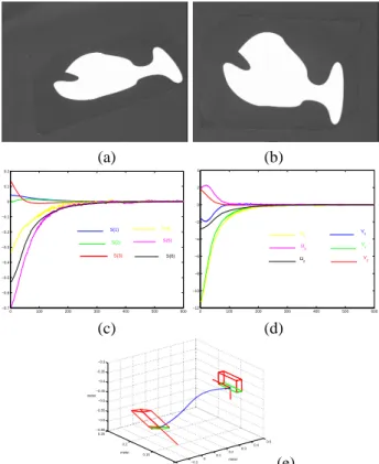
2.2.1 Complex motion
We first test our scheme for a displacement involving very large translation and rotation to realize between the initial and desired images (see Figures 1.a and 1.b). The inter-action matrix computed at the desired position has the fol-lowing form: Ls|s=s∗= −1 0 0 0.01 −0.52 0.01 0 −1 0 0.51 −0.01 0.01 0 0 −1 −0.02 −0.01 0 0 0 0 −0.33 −0.62 0 0 0 0 −0.61 0.09 0 0 0 0 −0.04 −0.08 −1 (2)
We can note that this matrix is block triangular with main terms around the diagonal. The value of its condition num-ber (equal to 2.60) is also very satisfactory. The obtained results are given on Figure 1. They show the good behavior of the control law. First, we can note the fast convergence towards the desired position. Then, there is no oscillation in the decrease of the visual features (see Figure 1.c), and there is only one small oscillation for only two components of the camera velocity (see Figure 1.d). Finally, even if the rotation to realize between the initial and the desired positions is very large, the obtained camera 3D trajectory is satisfactory (see Figure 1.e), while it was an important drawback for classical 2D visual servoing.
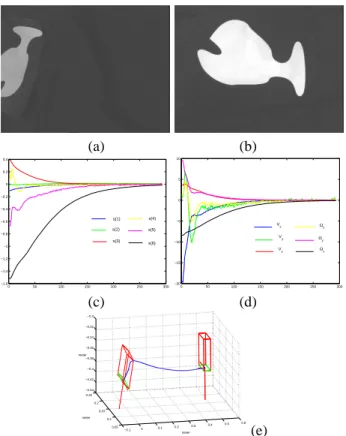
2.2.2 Results with a bad camera calibration and ob-ject occlusion
We now test the robustness of the method with respect to a bad calibration of the system. In this experiment, errors have been added to camera intrinsic parameters (25% on
the focal length and 20 pixels on the coordinates of the prin-cipal point) and to the object plane parameters ( bZ∗= 0.8m
instead of Z∗ = 0.5m where Z∗ is the desired depth
be-tween the camera and the object). We can also notice that the lighting conditions for the desired and the initial po-sitions given on Figure 2.a and 2.b are different. Further-more, an occlusion has been generated since the object is
not completely in the camera field of view at the begining of the servo. The obtained results are given in Figure 2. We can notice that the system converges despite the worse conditions of experimentations and, as soon as the occlu-sion ends (after iteration 30), the behavior of the system is similar to those of the previous experiment, which validates the robustness of our scheme with respect to modeling er-rors. (a) (b) 0 100 200 300 400 500 600 −0.7 −0.6 −0.5 −0.4 −0.3 −0.2 −0.1 0 0.1 0.2 S(1) S(2) S(3) S(4) S(5) S(6) 0 100 200 300 400 500 600 −12 −10 −8 −6 −4 −2 0 2 4 Vx Vy Vz Ωx Ωy Ωz (c) (d) −0.2 −0.1 0 0.1 0.2 0.3 0.4 0.5 0.1 0.15 0.2 0.25 −0.65 −0.6 −0.55 −0.5 −0.45 −0.4 −0.35 −0.3 meter meter meter (e)
Figure 1: Results for a complex motion: (a) initial image, (b) desired image, (c) visual features(s − s∗), (d) camera
velocity Tc, (e) camera 3D trajectory
2.3
Experimental results with objects
com-posed of a set of points
In this paragraph, we present similar experimental results obtained with objects composed of a set of points (see Fig-ure 3). The considered points have been extracted using Harris detector and tracked using a SSD algorithm. We can note however that the plots are noisy. It is mainly notice-able on the ωx and ωy components of the camera
veloc-ity whose value depends on5thorder moments (while ω z
and υzare not noisy at all since their value only depend of
moments of order 2). Despite this noise, the exponential decrease, the convergence and stability are still obtained, which proves the validity of our approach. This results can
even be improved using a sub pixel accuracy image tracker such as Shi-Tomasi algorithm [13].
(a) (b) 0 50 100 150 200 250 300 −1.6 −1.4 −1.2 −1 −0.8 −0.6 −0.4 −0.2 0 0.2 0.4 s(1) s(2) s(3) s(4) s(5) s(6) 0 50 100 150 200 250 300 −20 −15 −10 −5 0 5 10 Vx Vy Vz Ωx Ωy Ωz (c) (d) −0.1 0 0.1 0.2 0.3 0.4 0.5 0.6 0.05 0.1 0.15 0.2 0.25 −0.44 −0.42 −0.4 −0.38 −0.36 −0.34 −0.32 −0.3 meter meter meter (e)
Figure 2: Results using a bad camera calibration: (a) initial image, (b) desired image, (c) visual features(s − s∗), (d)
camera velocity, (e) camera 3D trajectory
3
Robust model-based tracking
3.1
Overview of the approach
This section addresses the problem of realizing visual ser-voing tasks by using complex objects in real environments. For that, we present a real-time model-based tracking of objects in monocular image sequences. This fundamental vision problem has applications in many domains ranging from augmented reality to visual servoing and even medi-cal imaging or industrial applications. The main advantage of a model-based method is that the knowledge about the scene (the implicit 3D information) allows improvements of robustness and performance by being able to predict hid-den movement of the object and acts to reduce the effects of outlier data introduced in the tracking process.
In the related literature, geometric primitives considered for the estimation are often points[4], segments, lines, con-tours or points on the concon-tours, conics, cylindrical objects or a combination of these different features. Another
im-50 100 150 200 250 300 350 50 100 150 200 250 50 100 150 200 250 300 350 50 100 150 200 250 (a) (b) 50 100 150 200 250 300 350 400 450 500 −3 −2 −1 0 1 2 3 0 500 1000 1500 0.1 0.2 0.3 0.4 0.5 0.6 0.7 0.8 0.9 1 (c) (d)
Figure 3: Results for complex images: (a) initial image, (b) desired image, (c) velocities, (d) features errors mean
portant issue is the registration problem. Purely geometric, or numerical and iterative approaches may be considered.
Linear approaches use a least-squares method to estimate
the pose. Full-scale non-linear optimization techniques (e.g., [9, 5, 8]) consists of minimizing the error between the observation and the forward-projection of the model. In this case, minimization is handled using numerical it-erative algorithms such as Newton-Raphson or Levenberg-Marquardt. The main advantage of these approaches are their accuracy. The main drawback is that they may be sub-ject to local minima and, worse, divergence.
Our method is fully described in [3]. Pose computation is formulated in terms of a full scale non-linear optimiza-tion using a 2D virtual visual servoing scheme [11, 14]. Our method takes the 2D visual servoing framework by controlling the motion of a virtual camera so that the pro-jection in the image of the object model perfectly fits with the current position of the object in the image acquired by the real camera. We thus obtain an image feature-based system which is capable of treating complex scenes in real-time without the need for markers. Contributions can be exhibited at three different levels:
• the analytical form of the interaction matrices Ls
re-lated to complex visual features including ellipses, cylinders, points, distances and any combination of these is easily obtained [6]. Determining an accurate approximation of this matrix is essential to obtain the convergence of the visual servoing. In [3], a com-plete derivation of interaction matrices for distances to lines, ellipses and cylinders are given. Furthermore, computational efficiency is obtained by ’stacking’
in-teraction matrices and by using a constant inin-teraction matrix cLsin the control law.
• the widely accepted statistical techniques of robust
M-estimation are employed. This is introduced directly in the virtual visual servoing control law by weighting the confidence on each feature. The Median Abso-lute Deviation (MAD) is used as an estimate of the standard deviation of the inlier data. Statistically ro-bust pose computation algorithm, suitable for real-time tracking techniques, have been considered.
• the formulation for tracking objects is dependent on
correspondences between local features in the image and the object model. In an image stream, these cor-respondences are given by the local tracking of fea-tures in the image. In our method, low level tracking of the contours is implemented via an adequate algo-rithm, called Moving Edges algorithm [1]. A local ap-proach such as this is ideally suited to real-time track-ing due to an efficient 1D search normal to a contour in the image. In a ’real world’ scenario, some features may be incorrectly tracked, due to occlusion, changes in illumination and miss-tracking. Since many point-to-curve correspondences are made, the method given here has many redundant features which favors the use of robust statistics.
3.2
Tracking results in visual servoing
exper-iments
Any visual servoing control law can be used using the out-put of our tracker (image-based, position-based or hybrid scheme). In the presented experiments, we have consid-ered a now well known 2 1/2D approach, already described in [10]. It consists in combining visual features obtained directly from the image, and features expressed in the Eu-clidean space. The 3D information can be retrieved either by a projective reconstruction obtained from the current and desired images, either by a pose estimation algorithm. In our context, since the pose is an output of our tracker, we consider in this paper the latter solution.
The complete implementation of the robust visual servo-ing task, includservo-ing trackservo-ing and control, was carried out on an experimental test-bed involving a CCD camera mounted on the end effector of a six d.o.f robot. Images were ac-quired and processed at video rate (50Hz).
In such experiments, the image processing is poten-tially very complex. Indeed extracting and tracking reliable points in real environment is a non trivial issue. The use of more complex features such as the distance to the projec-tion of 3D circles, lines, and cylinders has been demon-strated in [3] in an augmented reality context. In all ex-periments, the distances are computed using the Moving
a b
c d
Figure 4: Tracking in complex environment within a clas-sical visual servoing: Images are acquired and processed at video rate (25Hz). Blue: desired position defined by the user. Green: position measured after pose calculation. (a) first image initialized by hand, (b) partial occlusion with hand, (c) lighting variation, (d) final image with various occlusions
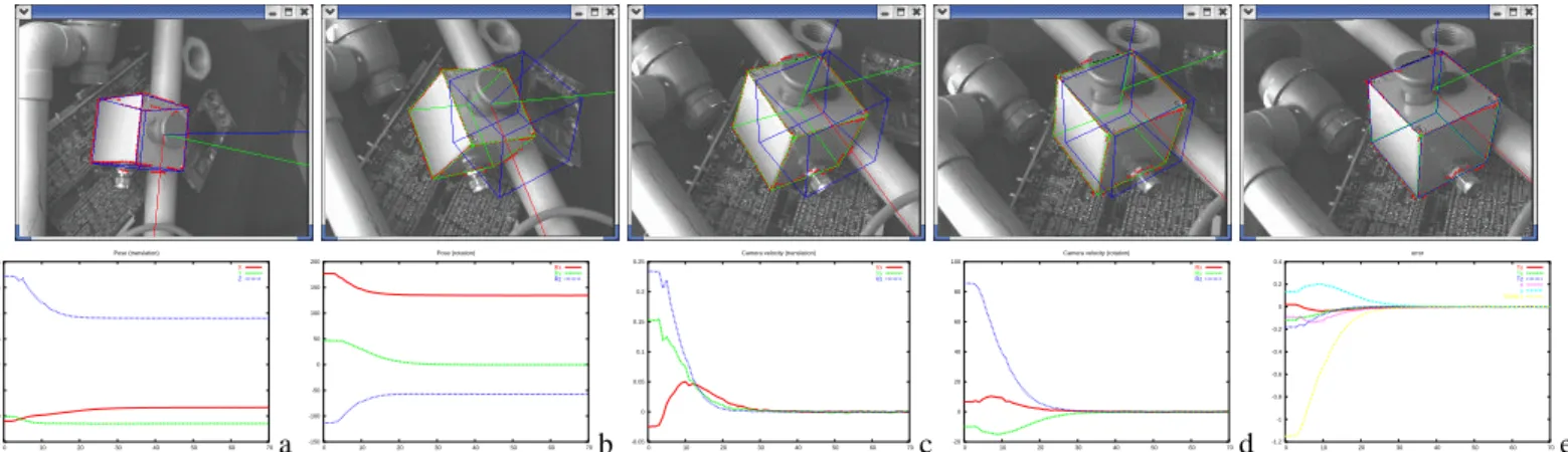
Edges algorithm previously described. Tracking is always performed at below frame rate (usually in less than 10ms). In all the figures depicted, current position of the tracked object appears in green while its desired position appears in blue. Three objects where considered: a micro-controller (Figure 4), an industrial emergency switch (Figure 5) and a video multiplexer (Figure 6).
To validate the robustness of the algorithm, the objects were placed in a highly textured environment as shown in Fig. 4, 5 and 6. Tracking and positioning tasks were cor-rectly achieved. Multiple temporary and partial occlusions by an hand and various work-tools, as well as modification of the lighting conditions were imposed during the realiza-tion of the posirealiza-tioning task. On the third experiments (see Figure 6), after a complex positioning task (note that some object faces appeared while other disappeared) the object is handled by hand and moved around. Since the visual servoing task has not been stopped, robot is still moving in order to maintain the rigid link between the camera and the object.
For the second experiment, plots are also shown which help to analyse the pose parameters estimation, the camera velocity and the error vector. In the second experiment, the robot velocity reaches 23 cm/s in translation and 85 dg/s in rotation. In other words, less than 35 frames were acquired during the entire positioning task up until convergence (see Figure 5e). Therefore the task was accomplished in less than 1 second. In all these experiments, neither a Kalman filter (or other prediction process) nor the camera
displace--0.1 0 0.1 0.2 0.3 0.4 0.5 0.6 0 10 20 30 40 50 60 70 Pose (translation) X Y Z a -150 -100 -50 0 50 100 150 200 0 10 20 30 40 50 60 70 Pose (rotation) Rx Ry Rz b -0.05 0 0.05 0.1 0.15 0.2 0.25 0 10 20 30 40 50 60 70 Camera velocity (translation)
Vx Vy Vz c -20 0 20 40 60 80 100 0 10 20 30 40 50 60 70 Camera velocity (rotation)
Rx Ry Rz d -1.2 -1 -0.8 -0.6 -0.4 -0.2 0 0.2 0.4 0 10 20 30 40 50 60 70 error Tx Ty Tz x y \theta z e Figure 5: 2D 1/2 visual servoing experiments: on these five snapshots, the tracked object appears in green and its desired position in the image in blue. Plots correspond to (a) pose (translation), (b) pose (rotation), (c-d) camera velocity in rotation and translation, (e) error vector s − s∗
.
Figure 6: 2D 1/2 visual servoing experiments: on these snapshots the tracked object appears in green and its desired position in the image in blue. The six first images have been acquired during an initial visual servoing step where the object is motionless. In the reminder images, object is moving along with the robot.
ment were used to help the tracking.
References
[1] P. Bouthemy. A maximum likelihood framework for determining moving edges. IEEE Trans. on Pattern Analysis and Machine intelligence, 11(5):499–511, May
1989.
[2] F. Chaumette. Potential problems of stability and con-vergence in image-based and position-based visual ser-voing, The Confluence of Vision and Control, pp. 66-78,
LNCIS Series, No 237, Springer-Verlag, 1998.
[3] A. Comport, E. Marchand, and F. Chaumette. A real-time tracker for markerless augmented reality.
ACM/IEEE Int. Symp. on Mixed and Augmented Real-ity, ISMAR’03, pp. 36–45, Tokyo, Japan, October 2003.
[4] D. Dementhon and L. Davis. Model-based object pose in 25 lines of codes. Int. J. of Computer Vision, 15:123– 141, 1995.
[5] T. Drummond and R. Cipolla. Real-time visual track-ing of complex structures. IEEE Trans. on Pattern Analysis and Machine Intelligence, 27(7):932–946, July
2002.
[6] B. Espiau, F. Chaumette, P. Rives: A new approach to visual servoing in robotics, IEEE Trans. on Robotics
and Automation, 8(3):313-326, June 1992.
[7] S. Hutchinson, G. Hager, P. Corke: A tutorial on visual servo control, IEEE Trans. on Robotics and Automation, 12(5):651-670, October 1996.
[8] D. Kragic and H.I. Christensen. Confluence of param-eters in model based tracking. In IEEE Int. Conf. on
Robotics and Automation, ICRA’03, volume 4, pages
3485–3490, Taipe, Taiwan, September 2003.
[9] D. Lowe. Robust model-based motion tracking trough the integration of search and estimation. Int. Journal of
Computer Vision, 8(2):113–122, 1992.
[10] E. Malis, F. Chaumette, and S. Boudet. 2 1/2 D vi-sual servoing. IEEE Trans. on Robotics and Automation, 15(2):238–250, April 1999.
[11] E. Marchand and F. Chaumette. Virtual visual ser-voing: a framework for real-time augmented reality.
Eurographics’02 Conf. Proc., Vol. 21(3) of Computer
Graphics Forum, pp. 289–298, Saarebrücken,
Ger-many, September 2002.
[12] O. Tahri, F. Chaumette. Application of moment in-variants to visual servoing IEEE Int. Conf. on robotics
and Automation, ICRA’03, Vol. 3, pp. 4276-4281,
Taipei, Taiwan, September 2003.
[13] J. Shi and C. Tomasi. Good features to track. In
IEEE Int. Conf. Computer Vision and Pattern Recogni-tion, CVPR’94, pages 593–600, Seattle, June 1994.
[14] V. Sundareswaran and R. Behringer. Visual servoing-based augmented reality. In IEEE Int. Workshop on