HAL Id: hal-02929749
https://hal.archives-ouvertes.fr/hal-02929749
Submitted on 3 Sep 2020
HAL is a multi-disciplinary open access
archive for the deposit and dissemination of
sci-entific research documents, whether they are
pub-lished or not. The documents may come from
teaching and research institutions in France or
abroad, or from public or private research centers.
L’archive ouverte pluridisciplinaire HAL, est
destinée au dépôt et à la diffusion de documents
scientifiques de niveau recherche, publiés ou non,
émanant des établissements d’enseignement et de
recherche français ou étrangers, des laboratoires
publics ou privés.
Users’ Power Multiplexing Limitations in NOMA
System over Gaussian Channel
Ahlem Haddad, Amor Nafkha, Faouzi Bader, Djamel Slimani
To cite this version:
Ahlem Haddad, Amor Nafkha, Faouzi Bader, Djamel Slimani. Users’ Power Multiplexing Limitations
in NOMA System over Gaussian Channel. The IEEE 8th International Conference on Wireless
Net-works and Mobile Communications (WINCOM’2020), Reïms, France. Oct 2020., Oct 2020, Reïms (
Virtual Conference ), France. �hal-02929749�
Users’ Power Multiplexing Limitations in NOMA
System over Gaussian Channel
Ahlem Haddad, Djamel Slimani
Electronics Department Faculty of Technology University of Setif-1, Setif 19000, Algeria Email: ahlem.haddad,[email protected]
Abstract—Non-Orthogonal Multiple Access (NOMA) is one of the promising techniques to ensure very high spectral effi-ciency in 5G mobile communications and beyond.In contrast to the orthogonal multiple access (OMA) technique, the NOMA shows outstanding performances in terms of throughput, user fairness, low latency and compatibility with the current and future communication systems. In this paper, we analyze the capacity region in NOMA system and the limited number of multiplexed users under a given power allocation vector (i.e. symmetric/asymmetric channel). Moreover, we have investigated the effect of large constellation order on the power allocation and bit error rate (BER). Comparisons between the coded and uncoded schemes are also presented.
I. INTRODUCTION
5G communication systems use the most promising tech-niques that would guarantee the best performance (KPI- Key Performance Indicator) in terms of throughput, energy effi-ciency, and also the best low latency indicators [1], [2]. Two principal features of 5G are required: the latency of 1ms and the capacity of supporting for 10 Gb/s throughput [3]. NOMA is one of the highly recommended technologies to be used in future communication systems. Especially for its capacity to improve the efficiency use of the resources by exploiting channel quality differences among users and the use of ad-vanced successive interference cancellation (SIC) receivers [4], [5]. The NOMA technique maintains a good backward com-patibility when combined with orthogonal frequency-division multiple access (OFDMA) [6]. Moreover, NOMA is highly expected to increase system throughput due to the fact that each user uses all the bandwidth resource. To ensure this performance, NOMA scheme superposes multiple users in the same radio resource with different transmission power There are different types of NOMA techniques, including code-domain and power-domain. In the code domain, NOMA scheme uses a specific spreading sequence for each user in order to share the entire resource with the rest of the active users while in the power domain, NOMA uses the power as a mode of sharing the spectral resource with different users [7]. In the latter, NOMA exploits the differences in channel gains between the users in order to multiplex through the power allocation.
In in this paper, we are interested into the NOMA downlink scenario. The base station adds up the users signals in a linear way under certain power partitions to balance the sum rate
N
Amor
Nafkha, Faouzi Bader
IETR/SCEE, UMR CNRS 6164, CentraleSup´elec
Avenue de la Boulaie, Cesson S´evign´e, 35576, France Email: amor.nafkha,[email protected]/
of all multiplexed users and the throughput fairness among individual users [8]. However, at the receivers level, users which benefit from the strong channels conditions decode and cancel successively the messages of the weak users to be able to decode their signals. As the authors confirm in [9], SIC is the heart of NOMA. It allows to separate the superimposed signals at the receiver [11].
In this paper, we first focus on the fundamentals of downlink NOMA scheme and we emphasize their keys: coded or un-coded signals superposition (SC) at the BS and the SIC at the receivers. Then, we discusses the channel capacity comparison between the OMA with the NOMA overs simulations in the downlink communication. Accordingly, we highlight and discuss the simulation results of downlink NOMA chain And analyze the multiplexing level of the users and its limits over AWGN channel. Finally, we draw the main conclusions and we give some insights.
II. SYSTEM MODEL
In this section, we explain the concept of single-cell down-link scenario, Let assume that the baste station (BS) and each user are equipped by a single antenna. The overall transmission bandwidth is normalized to the unit for ease of computation. The system model contains a base station, and N users. Let kh1k2; i = 1,2,...,N be the square of channel
gain amplitude, between the BS and the ith user, arranged in the ascending order, i.e., kh1k2 is the smallest and khNk2
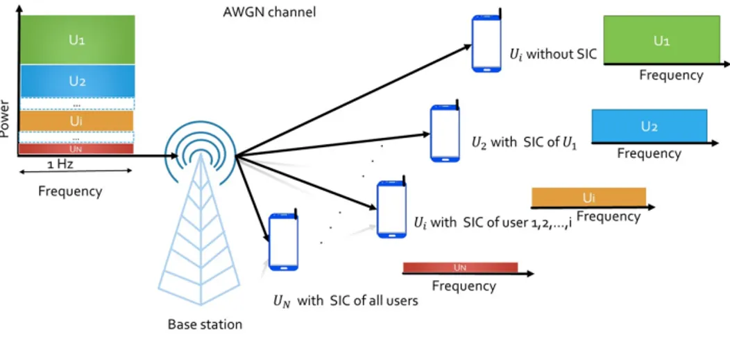
is the greatest. Therefore, the first user U1 is the weakest user in terms of the channel conditions while the UN is the strongest one. In what follows, we assume a Gaussian channel between BS transmitter and different receivers with a fixed gain h1, h2, . . . , hN . Fig. 1 represents a downlink NOMA
scheme with N users.
The BS transmits the signal of N users simultaneously by multiplexing their signals using the SC. The Data is sent for each user over the entire bandwidth while the power resource is shared between them. We assume that the channel state information (CSI) of different users is available at the base station. The BS allocates the ithlowest power Pi to the ithuser Ui , Pi = Pt ∗ αi with Pt is the total available power at the BS, αi is the power allocation factor of Ui. Note that ∑i=1αi= 1. So,
without limiting the general scope of the other users, the weakest user U1benefits from the highest power allocation,
Fig. 1. NOMA downlink scenario scheme with N users
Fig. 2. The basic principle of SIC
while the lowest power is given to the strongest user UN. On
the receiving end, each user receives the signal transmitted by the BS which includes its signal and the signals of other users. All these signals are multiplexed with different power ratios. The integrated SIC algorithm at the users terminals level allows that the strongest users eliminate the weak users signals successively .Thus, each user Ui, i = 1, 2, . . . , N decodes all
the signals of users Uk with k < i. Unlike the strong users, the weak users consider stronger user signals as interference. Fig. 2 details the principle of SIC based on the orthogonal frequency-division multiplexing (OFDM).
The jth user’s data Uj can be obtained in the jth iteration
where j ∈ {0, 1, ..., N − 1}. The received signal at the ith
receiver Ui can be expressed as
yi= hi∗ Xt+ wi (1) with Xt= N
∑
i=1 √ Pi∗ xi (2)where wi is complex-Gaussian distributed additive noise
with zero mean and variance σi2, and Xt is the transmitted
signal from the BS, and xi is the signal for the user Ui.
According to the NOMA principle, the SC process is implemented at the BS while the SIC process is implemented at the receiver of strong users. We assume that these process are perfectly implemented and there are no error propagation. So, all the strong users can decode correctly their signals
while the weakest users remove the inter-user interference. The throughput of Ui, Ri is represented as
Ri= log2(1 +
Pi|hi|2
|hi|2∑Nm=i+1Pm+ σi2
) (3) The strong user has a better channel condition, but its power is the lowest one compared to the other users. Thus the strong user receives high interference from weak users. However, the weak user is assigned biggest power allocation. Note that the achievable rate of user N is given by
RN= log2(1 +
PN|hN|2
σi2 ) (4) III. DOWNLINKCHANNELCAPACITYCOMPARISON
OMA/NOMA
In this section we compare the capacity region of NOMA and OMA. In downlink NOMA, users use the same entire 1 Hz bandwidth and the same time recourse. we assume that there is a single-cell with two users. we assume also that the signals pass by AWGN channel and kh2k2> kh1k2. Using (3) and (4),
the NOMA throughput of the two users is given successively by R1= log2(1 + P1|h1|2 |h1|2P2+ σ12 ) (5) R2= log2(1 + P2|h2|2 σ22 ) (6)
However in downlink OMA, the bandwidth is shared between the users. Thus the assigned bandwidth to the first user is β Hz while the second user obtains (1 − β ) Hz with (0 < β < 1). The achievable data rate by user 1 and user 2 are, respectively, expressed as RO1= β log2(1 + P1|h1|2 |h1|2P2+ σ12 ) (7) RO2= (1 − β ) log2(1 + P2|h2|2 σ22 ) (8) NOMA scheme controls the rate of the two users one and two by adjusting the power resource allocation given in (5) and (6). So, if the power ratio P1/P2 is well chosen
the users of NOMA can benefit from throughput fairness. According to [10], [11], if an asymmetric channels, where the signal-to-noise ratios (SNRs) of the two users are different, is considered, it can be numerically shown that the values of RO1and RO2, given, respectively, (5) and (6), are considerably
higher than those of RO1.
In the downlink, Fig. 3 shows the worst-case situation where the users are under a symmetric channel scenario conditions kh1k = kh2k. It is clear that the rate fairness is identical for
Fig. 3. Channel capacity of OMA and NOMA in symmetric channels
OMA and NOMA for a different signal to noise ratios (SNR), ηi= Ptkhik2/σi2. The sum rates of the users are also equal
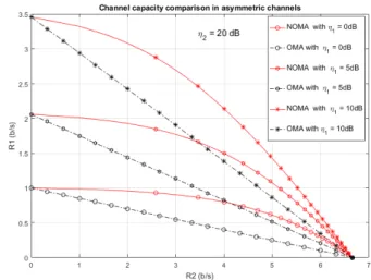
for the NOMA and the OMA schemes in the 5 configurations given in Fig. 3. On the other hand, the best scenario for NOMA is when kh1k2< kh2k2. Thus mean the users have asymmetric
conditions channels, Fig. 4 represents this scenario for two users under asymmetric channels.
The SNR of the first user is varied while the SNR of the second user remains fixed at 20 dB (without loss of generality when kh1k2< kh2k2 ). The overall throughput and the rate
fairness of user 1 and user 2 in NOMA are superior to those of OMA. In fact, this knowledge of the NOMA channel capacity allows to assign an optimal power ratio between the users
Fig. 4. Channel capacity of OMA and NOMA in asymmetric channels
in order to provide the highest possible throughput for users while respecting the rate fairness. So the NOMA system ,in asymmetric channels, can achieve higher sum ergodic capacity compared to the OMA system. Therefore, the NOMA system is superior in terms of the capacity region than OMA.
IV. SIMULATION RESULTS
In this section we analyze the BER performances of the NOMA technique under Gaussian channel for large constella-tion order Secconstella-tion IV-1 and for three users Secconstella-tion IV-2. In first section, the analysis of a system with two-users under 4QAM and 16QAM is presented, then the NOMA with multiple users system under BPSK is simulated. Highlighting the effect of using a large modulation order and the effect of increasing the users number. In the simulations, we mean by coded data that the user use a channel coding while in the case of free channel coding we use the uncoded data therm. For each test we analyze the scenario in two cases: the case where the users data is uncoded, then the case where the data is coded with a convolutional code based on a rate of 1/2 and constraint length of 7. In the latter case, the data at the receiver side are decoded using a hard viterbi decoder. All the tables Results are given for a bit error rate BER =10−4 in the case of users with coded data.
1) Performance Analysis under large constellation sizes: In this subsection, we analyze the NOMA chain under 4-QAM and 16-QAM in order to highlight the modulation order effect. Tables I and II represent respectively , NOMA-4-QAM Eb/N0 and NOMA-16QAM Eb/N0 for two users (N = 2)
with different power allocation factors. In the case of the 4-QAM, the value of α1 assigned to the weakest user is
varied from α1= 0.55 to α1= 0.95 with a step of 0.05.
However, the value of α1 in the 16-QAM case is varied
from α1= 0.91 to α1= 0.99 with a step of 0.01. The α2 is
calculated as α2= 1 − α1. Note that the choice of αi depends
TABLE I
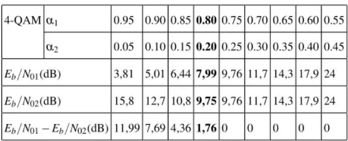
ACHIEVED PERFORMANCES FOR A4-QAM NOMASYSTEM WITH TWO USERS AT ABER=10−4AND DIFFERENT VALUES OFEb/N0, α1ANDα2
4-QAM α1 0.95 0.90 0.85 0.80 0.75 0.70 0.65 0.60 0.55 α2 0.05 0.10 0.15 0.20 0.25 0.30 0.35 0.40 0.45 Eb/N01(dB) 3,81 5,01 6,44 7,99 9,76 11,7 14,3 17,9 24 Eb/N02(dB) 15,8 12,7 10,8 9,75 9,76 11,7 14,3 17,9 24 Eb/N01− Eb/N02(dB) 11,99 7,69 4,36 1,76 0 0 0 0 0 TABLE II
ACHIEVED PERFORMANCES FOR A16-QAM NOMASYSTEM WITH TWO USERS AT ABER=10−4AND DIFFERENT VALUES OFEb/N0, α1ANDα2
16-QAM α1 0.99 0.98 0.97 0.96 0.95 0.94 0.93 0.92 0.91
α2 0.01 0.02 0.03 0.04 0.05 0.06 0.07 0.08 0.09
Eb/N01(dB) 7,62 7,58 8,56 9,87 11,6 13,7 16,4 20 26,2
Eb/N02(dB) 26 22,9 21,1 20 18,9 18,2 17,5 20 26,2
Eb/N01− Eb/N02(dB) 18,38 15,32 12,54 10,13 7,3 4,5 1,1 0 0
the different modulation orders. The best configuration are represented in bold. The best value for the pair (α1, α2) for
the 4-QAM is (α1= 0.80, α2= 0.20) and for 16-QAM is
(α1= 0.93, α2= 0.07). These pairs are chosen in terms of
the lower Eb/N0i possible with (Eb/N01− Eb/N02 < 2dB).
We notice that the 16-QAM gives the worst results with Eb/N01= 16.4 dB and Eb/N01= 17.5 dB. We notice also that
the power allocation factor for U2is very low in the 16-QAM
case (α2= 0.07). In the other hand, the 4-QAM modulation
guarantees a Eb/N01< 9.75 dB for the two users. We note that
a 64-QAM simulations are done for different values of α1and
α2, but they have not achieved the bit error rate of 10−4. All
the simulation have given a bit error rate higher than 10−2. Figures 5 and 6 give the simulation results of BER in terms of Eb/N0 for for the best pair of power allocation factors
chosen from Tables I and II respectively. Lines with star(*) depicts coded signal, however, lines with circle (o) the uncoded signal. In the first scenario, the BS multiplexes the uncoded data and send them to two users U1ans U2while in the second
scenario the BS encodes the users data and multiplexes them, then it sends the multiplexed signal to the users.
In both scenarios the U1 without SIC uses directly the
received signal considering the U2 signal as interference.
However, the U2 uses the SIC algorithm to obtain its data.
We observe in the figures that the U1and U2with coded data
are better in terms of BER from a threshold Eb/N0special for
each user and for each modulation size. For the BPSK from Eb/N0< 5B, the coded data scenario BER is less good than
the uncoded data scenario for U1 and U2. For the 4QAM the
Fig. 5. NOMA scheme using 4-QAM modulation with coded and uncoded BER signal performances
Fig. 6. NOMA scheme using 16QAM modulation with coded and uncoded BER signal performances
Eb/N0 threshold is 5.8 dB while for the NOMA-16QAM the
Eb/N0 threshold goes up to 13.1 dB.
All these simulation results confirm that the small modu-lation size are more efficient in the NOMA communication system. Therefore, the large modulation size decreases the NOMA performances. Therefor, we can affirm that the small modulation order is the most suitable modulation type for the NOMA systems and this is due to the difficulty of reconstructing the multiplexed signals with close constellations as in the case of 64QAM and 16QAM. However, the case of 4QAM is easier to distinguish the modulation symbols.
2) Performances analysis under multiple users: To evaluate the maximum number of users in the NOMA system, the users number is varied from 2 to 4 users. The BPSK modulation is chosen following to the results of the previous section. Since
the small modulation order is most suited to NOMA. Table III and table IV shows Eb/N0 results for BER= 10−4 in BPSK
for 2 and 3 users respectively. The best configuration of power allocation is given in bold. For 4 users all the configurations do not allow that all the users achieve the bit error rate of 10−4.
TABLE III
ACHIEVED PERFORMANCES FOR ABPSK NOMASYSTEM WITH TWO USERS AT ABER=10−4AND DIFFERENT VALUES OFEb/N0, α1ANDα2
BPSK α1 0.95 0.90 0.85 0.80 0.75 0.70 0.65 0.60 0.55 α2 0.05 0.10 0.15 0.20 0.25 0.30 0.35 0.40 0.45 Eb/N01(dB) 3.92 5.06 6.61 8.1 9.94 12 14.6 18.1 22.8 Eb/N02(dB) 19.5 14.6 12.2 10.6 10.1 12 14.6 18.1 22.8 Eb/N01− Eb/N02(dB) 15.58 9.54 5.59 2.5 0.16 0 0 0 0 TABLE IV
ACHIEVED PERFORMANCES FOR ABPSK NOMASYSTEM WITH THREE USERS AT ABER=10−4AND DIFFERENT VALUES OFEb/N0, α1, α2ANDα3
BPSK α1 0,74 0,72 0,71 0,73 0,7 0,71 0,7 0,69 0,74 0,69 0,7 α2 0,2 0,21 0,22 0,2 0,23 0,21 0,22 0,25 0,19 0,24 0,25 α3 0,06 0,07 0,07 0,07 0,07 0,08 0,08 0,06 0,07 0,07 0,05 Eb/N01(dB) 14,3 16,6 17,9 15,5 19,5 18,6 20,2 20,1 14,5 21,1 17,5 Eb/N02(dB) 17,7 18,4 18,4 19,3 19,5 20 20,3 20,1 20,5 21,1 17,5 Eb/N03(dB) 18,9 18,4 18,4 19,3 19,5 20 20,3 20,1 20,5 21,1 20,5 Eb/N02-Eb/N01(dB) 3,4 1,8 0,5 3,8 0 1,4 0,1 0 6 0 0 Eb/N03-Eb/N02(dB) 1,2 0 0 0 0 0 0 0 0 0 3 Eb/N03-Eb/N01(dB) 4,6 1,8 0,5 3,8 0 1,4 0,1 0 6 0 3
The best configuration of power allocation factors for NOMA using BPSK modulation under 2 users is (α1=
0.75, α2= 0.25) with a maximum of Eb/N0max = 10.1 dB,
while under 3 users the best configuration is (α1= 0.71, α2=
0.22, α3= 0.07) with a maximum of Eb/N0max= 18.4 dB. We
notice that the NOMA systems with small user number allow to achieve a bit error rate of 10−4in worse channel conditions compared to NOMA system with big user number.
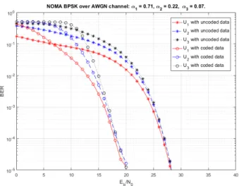
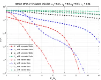
The best configuration are shown in Fig. 7 and Fig. 8. They represents system with 2 and 3 active users respectively while Fig.9 represents a system with 4 users with (α1= 0.74 dB,
α2= 0.2dB, α3= 0.04dB, α4= 0.02 dB). This simulation is
chosen because it is among the best simulation under 4 users that two users with coded data at least achieve the bit error rate of 10−4. We note that, lines with star(*) depicts coded signal, and lines with circle (o) the uncoded signal.
Fig. 7. NOMA scheme with coded and uncoded BER signal performances under 2 users
Fig. 8. NOMA scheme coded and uncoded BER signal performances under 3 users
The scenario with coded data is always less good in the worse channel conditions. The Eb/N0threshold for the BPSK
with 2 users is 5.1 dB and 11.3 dB for 3 users. Thus the coded data scenario is better than the uncoded data one when the Eb/N0 is bigger than these values. We notice that this
Eb/N0 threshold is smaller in the case of small users number.
We notice also that NOMA under two users is the best configuration. However, in the case of 4 users we have just one user with uncoded data which achieve small bit error rate and 2 user in the case of coded data provided that they have good channel conditions. Therefore, we affirm that NOMA with small number in a signle-cell is more efficient. However, more the users number increases more the SIC is complex and the errors propagation increase fast. In addition when the number of users increases, the power allocation is became very
Fig. 9. NOMA scheme coded and uncoded BER signal performances under 4 users
complicated to assign to the users. V. CONCLUSION
In this paper, the NOMA theory in downlink scenario for a single-cell with multiple users is described. The channel capac-ity of NOMA and OMA for asymmetric and symmetric users channels conditions is compared. Perforamnce Analysis under small and large constellation order are highlighted, tested and compared for two, three and four NOMA multiplexed users. The simulation is carried on the superiority of NOMA with crypted and uncrypted data respectively. As a result, the complexity of NOMA system is confirmed when the number of users or the modulation order increase.
REFERENCES
[1] Q. Li, H. Niu, A. Papathanassiou, and G. Wu, 5G network capacity: Key elements and technologies, IEEE Veh. Technol. Mag., vol. 9, no. [2] 1, pp. 7178, Mar. 2014. Y. Yan, A. Li, and H. Kayama, ”Superimposed
radio resource sharing for improving uplink spectrum efficiency,” Asia-Pacific Conference on Communications, pp.15, Oct. 2008.
[3] [1] F. Boccardi et al., Five Disruptive Technology Directions for 5G, IEEE Commun. Mag., vol. 52, no. 2, Feb. 2014,pp. 7480.
[4] Proposed solutions for new radio access, Mobile and wireless communi-cations enablers for the 2020 information society (METIS), Deliverable D.2.4, Feb. 2015.
[5] X. Chen, A. Benjebbour, Y. Lan, A. Li, and H. Jiang, Impact of rank optimization on downlink non-orthogonal multiple access (NOMA) with SU-MIMO, in 2014 IEEE International Conference on Com-munication Systems, Macau, China, Nov. 2014, pp. 233237, doi: 10.1109/ICCS.2014.7024800.
[6] Y. Saito, A. Benjebbour, Y. Kishiyama, and T. Nakamura, System level performance evaluation of downlink non-orthogonal multiple access (NOMA), in Proc. IEEE Annual Symposium on Personal, Indoor and Mobile Radio Communications (PIMRC), London, UK, Sept. 2013. [7] L. Dai, B. Wang, Z. Ding, Z. Wang, S. Chen, and L. Hanzo, A Survey of
Non-Orthogonal Multiple Access for 5G, IEEE Commun. Surv. Tutor., vol. 20, no. 3, pp. 22942323, 2018, doi: 10.1109/COMST.2018.2835558. [8] L. Dai, B. Wang, Y. Yuan, S. Han, C. I, and Z. Wang, Non-orthogonal multiple access for 5G: solutions, challenges, opportunities, and future research trends, IEEE Commun. Mag., vol. 53, no. 9, pp. 7481, Sep. 2015, doi: 10.1109/MCOM.2015.7263349.
[9] W. Shin, M. Vaezi, B. Lee, D. J. Love, J. Lee, and H. V. Poor, Non-Orthogonal Multiple Access in Multi-Cell Networks: Theory, Perfor-mance, and Practical Challenges, IEEE Commun. Mag., vol. 55, no. 10, pp. 176183, Oct. 2017, doi: 10.1109/MCOM.2017.1601065.
[10] S. M. R. Islam et al., Power-Domain Non-Orthogonal Multiple Access (NOMA) in 5G Systems: Potentials and Challenges, IEEE Commun. Surveys Tutorials, DOI:10.1109/COMST.2016.2621116.
[11] D. Tse and P. Viswanath, Fundamentals of Wireless Communication. Cambridge, U.K.: Cambridge Univ. Press, 2005.