This is an author-deposited version published in:
http://oatao.univ-toulouse.fr/
Eprints ID: 6655
To link to this article: DOI: 10.1115/1.4003713
URL:
http://dx.doi.org/10.1115/1.4003713
To cite this version:
Binder, Nicolas and Le Guyader, Sebastien and
Carbonneau, Xavier Analysis of the Variable Geometry Effect in Radial
Turbines. (2012) Journal of Turbomachinery, vol. 134 (n° 4). pp.
041017.1-041017.9. ISSN 0889-504X
O
pen
A
rchive
T
oulouse
A
rchive
O
uverte (
OATAO
)
OATAO is an open access repository that collects the work of Toulouse researchers and
makes it freely available over the web where possible.
Any correspondence concerning this service should be sent to the repository
administrator:
[email protected]
Nicolas Binder
1 e-mail: [email protected]Sebastien Le Guyader
e-mail: [email protected]Xavier Carbonneau
e-mail: [email protected] Institut Supérieur de l’Aéronautique et de l’Espace (ISAE), Université de Toulouse, 10 Avenue Edouard Belin, BP 54032, 31055 Toulouse Cedex 4, FranceAnalysis of the Variable
Geometry Effect in Radial
Turbines
The influence of variable geometry stators on the stage behavior is analyzed from both theoretical and experimental points of view. A theoretical analysis of the trajectory of some pressure-ratio lines in a loading-to-flow-coefficient diagram leads to the definition of a specific dimensionless parameter: the reduced section. This parameter is represen-tative of the stator geometric configuration and is thus expected to be a good candidate to describe the variable geometry problem. From a theoretical point of view, this param-eter is no less than the formal expression of the link between the geometric configuration of the stator and the behavior of the stage. An experimental approach decomposed in three phases is then led to evaluate this assessment. The results clearly demonstrate the crucial influence of the reduced section in the operating point definition. It leads to the conclusion that from a theoretical point of view, the two solutions mainly used in the industry for variable geometry stages (variation of the height or of the opening position of the stator blades) are equivalent provided that they are sanitized of their respective technological drawbacks. It has also been shown that the geometric configuration of the stator chosen to reach a specific value of the reduced section has some incidence on the efficiency of the stage. This observation gives some opportunities for optimization, for which some axis of reflection is given. 关DOI: 10.1115/1.4003713兴
1 Introduction
Basically, the only purpose of a turbine stage is to supply en-ergy to devices such as electric generators or compressor stages. This energy is taken from the total enthalpy of the inlet fluid, which varies with the flow conditions and with the application considered. The stage design is focused on this set of information, thus defining the stage specification. Designing is a subtle process requiring as much empiric experience as theoretical knowledge. The development gets even more complex if the stage is meant to run under severe variations of functioning conditions. In this case, the specification 共design point兲 is no more unique. The perfor-mance objective might be redefined. For example, an average ef-ficiency level over a wide range of functioning can be preferred to excellent peak efficiency over a limited operating range. In the design process of a radial turbine, it usually leads to consider the necessity of a stator, as it is generally admitted that a vaned stator improves the peak efficiency since it tightens the operating range. An analysis over a large number of stages关1兴 confirms this as-sessment. Anyway, a discussion of this conclusion is proposed in Ref.关2兴, as the configurations 共roughness and specific speeds兲 of vaneless stages were generally not suitable to good efficiency. A strict comparison is then proposed whose conclusions tend to dis-agree with the general assumption.
Prior to efficiency optimization, the designer should be con-cerned by the basic ability of a single stage to reach given points in the map. Even with the benefit of the diameter reduction term in the Euler equation, which increases the influence of rotational speed, the characteristic evolution of the mass-flow of a radial turbine is not much wider than that of a simple nozzle共as pre-sented, for example, in Ref.关3兴兲. The operating range of the stage is thus restricted to this characteristic zone of the map: The rest of the map is not accessible. This exclusion of possible operating
point can be a problem in some applications. For example, in the case of turbocharging, it limits the good matching between the turbine stage and the engine on its whole operating range. Variable geometry stages have been developed for that purpose. By modi-fying the stage permeability through the variation of a geometric section in the static part, the reduced mass-flow and the pressure-ratio values are partially discoupled. Different technical solutions exist, focusing on the casing modification 共see Ref. 关4兴, for in-stance兲 or on the alteration of the vaned stator properties. In the latter, the principle is to adapt the stator throat section to inlet flow conditions, as presented in Ref. 关5兴. This variation is generally obtained by 共i兲 the modification of the incidence of the stator blades and共ii兲 the variation of the height of the vanes by using a sliding shroud. On the one hand, the choice of a variable-opening stator raises the necessity of mechanical clearances between the stator blades and the casing where severe secondary flows de-velop. A quick estimation of the losses generated is accessible in Ref.关6兴 and, more accurately, in Ref. 关7兴. Moreover, the clearance is often created by intrusive spacers whose wakes interact with the blades, as presented in Ref.关8兴 or Ref. 关9兴. On the other hand, the movable-wall solution imposes partial admission on the height of the rotor with severe secondary flow at the leading edge of the blades. The first solution presents better efficiency levels, accord-ing to Ref.关10兴, due to better inlet incidence adaptation along the operating range.
Beside the discussion over the benefits and drawbacks of each of these technical solutions, it is the variable geometry nozzle concept in itself that should be studied. No clear detail of the physical process is found in the literature. Sporadic design rules are proposed, and few corrections of models were implemented. When found, it is done by considering a variable geometry stage as a derivation of a fixed geometry stage. The adjunction of vari-able geometry is just treated as another design step, and not as a specificity of the stage, which should lead to a specific design from the beginning. Some attempts were made 共Ref. 关11兴, for instance兲 but lack hindsight in the global variable geometry ap-proach. The present work aims at the global comprehension of the variable geometry effect, whatever the technical solution, and at the identification of the relevant parameters of the problem. In a
first part, an original theory will be recalled and applied to the variable geometry concept. This theoretical consideration is the basis on which the experimental approach is built and presented in a second part. In the third part of the paper, results are presented and then discussed in a conclusion.
2 Theoretical Issues
From a theoretical point of view, four dimensionless parameters are required to describe the behavior of a radial turbine stage 共when neglecting the Reynolds number influence and the gas properties’ variations兲. Usually, those parameters are the reduced mass-flow, the reduced speed, the pressure-ratio, and the effi-ciency. However, other dimensionless parameters could be used such as flow and loading coefficients defined as follows:
= m˙ i4U4 D42 4 共1兲 =⌬H U42 共2兲
Recent work关12兴 has demonstrated the relevance of these param-eters by expressing a formal link between them:
= · 4
再
共 . ts兲 1/␥共S3ⴱ兲−1 +冉
Pi5 P5冊
1−␥/␥D 5 D4共S5 ⴱ兲−1 ts冋
1 −ts冋
1 −冉
1 ts冊
␥−1/␥册册
冎
−冉
D5 D4冊
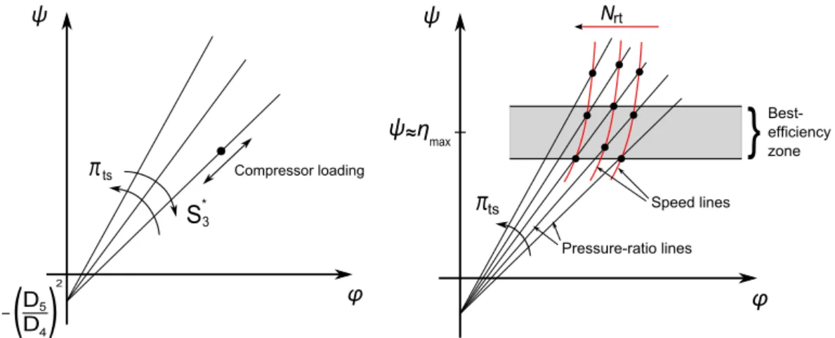
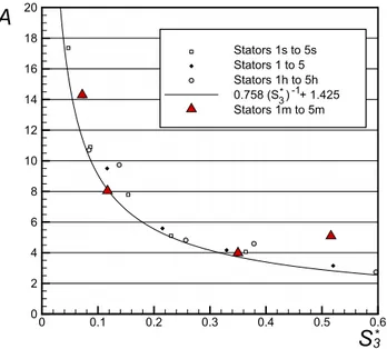
2 共3兲 where S3ⴱ= S3 D42D3 D4 sin共␣3兲 共4兲 S5ⴱ= S5 D42tan共5兲 共5兲 and =P5 P4 共6兲This equation represents the trajectory of a functioning line in a − map. It has thus been shown that for pressure-ratio lines 共ts= const兲 of a given stage, the trajectory is linear 共in that case, Eq.共3兲 reduces to=A−B兲 with a slope A mainly depending on the pressure-ratio value itself and on two dimensionless cross
sec-tions representative of the stator geometry at the throat共S3ⴱ兲 and of the rotor geometry at the outlet共S5ⴱ兲. The intercept B is defined by the trim of the rotor. Figure 1 illustrates this theoretical result and the features of this alternative turbine map describing the stage behavior.
This assessment gives a new perspective to the variable geom-etry concept. Generally, the variable geomgeom-etry effect is associated with a variation of a geometric section of the stator. Actually, the behavior alteration is more likely to originate from a variation of the reduced section. For a given pressure-ratio, shifting the stator geometry changes the value of S3ⴱ. Subsequently, the slope of the pressure-ratio line is modified: The functioning trajectory has changed.
This property of pressure-ratio lines has been observed in both experimental共see Ref. 关12兴兲 and numerical 共see Ref. 关13兴兲 results with quite good agreement. However, reality differs slightly from the theory concerning the intercept of the lines. According to Eq. 共3兲, the intercept is constant and common to each of the lines. A displacement of this point has been observed and correlated with the evolution of the intermediate pressure-ratio . Anyway, S3ⴱ seems to be a good candidate as a parameter to describe the vari-able geometry problem. Its presumed importance in the process is at the very core of this experimental study, the approach of which we will now describe.
3 Experimental Approach
The theoretical analysis leads to consider that the value of S3ⴱis most important in the variable geometry process. In that line, three statements follow.
1. If the reduced section variation is the dominant effect, then both of the classical solutions 共opening or blade’s height variation兲 are equivalent provided that they are sanitized of their technological drawbacks 共spacers, stator clearances, partial loading at the inlet of the rotor, etc.兲.
2. It should be possible to reproduce the behavior of a variable-opening stator without changing the variable-opening angle. 3. Two different geometric stator configurations generating the
same value of reduced section should behave the same way. In order to examine these assessments, series of stator geometries are tested on a reference stage.
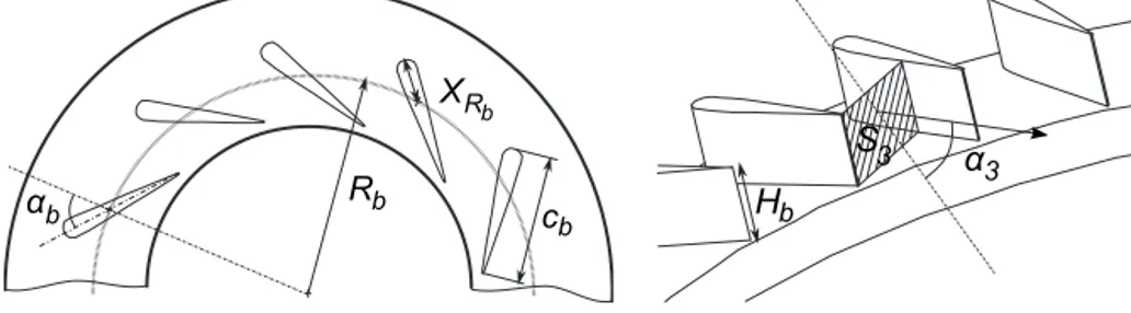
3.1 Geometric Configurations of the Stator. The definition
of S3ⴱ in Eq.共4兲 expresses an implied dependence to geometric factor constituting the stator. More specifically, for a given blade section, the value of S3ⴱcan be modified by changing共see Fig. 2 for illustration兲 the following:
• the angle of the blades共␣b兲
• the height of the blades共Hb兲 • the radial position of the blades共Rb兲
• the chord of the blades共cb兲
• the number of blades共Nb兲
It has been decided that the reference on the blade to set the radial position Rb should be a fixed position from the leading edge. This particular point共XRb兲 is thus at a fixed distance from
the leading edge, whatever the actual chord of the blade. It is also the point for which the blade’s angle␣bis measured. This point
would be the position of the pivot on a classic variable-opening stator.
The dependence of the reduced section to these parameters can-not be expressed by an analytic expression. A specific routine, taking the airfoil section into account, has been developed to ob-tain the value of the geometric cross section共S3兲 at the throat of the stator. The characteristic radii and angles are also estimated in order to build the reduced section of a known stator geometry as accurately as possible. However, a given value of S3ⴱcan be ob-tained by different combinations of the geometric factors.
Three groups of stator configurations are defined according to the three aforementioned statements. The first deals with the com-parison between the two variable geometry solutions 共height or opening variation兲. This group is a series of declinations of the reference stator, by variation of the opening angle共five values of ␣bfrom closed to open position兲, and of the blade’s height 共three
values of Hb兲. Fifteen stator configurations are thus implemented
on the stage without clearances at the hub and shroud. In order to avoid partial loading at the inlet of the rotor, it has been decided to match the rotor inlet to the stator blade’s height, even if it implies a modification of the rotor geometry. The trimming configuration of the inducer of the rotor is thus adapted to the modifications of the height of the stator blades; the rotor outlet diameter is identical for all of the geometries. At initial blade’s height, the stators are quoted from 1共closed position兲 to 5 共open position兲. Stator 3 is the reference stator. Then, “small” stators 1s – 5s共small height of blades兲 are defined together with the “high” stators 1h–5h 共high height of blades兲. The characteristics of the stators are given in Table 1.
The second group of stators aims at the segregation of the in-fluences of the reduced section and the opening position. In that purpose, four stators were built with the opening angle of the blades fixed at the reference opening position. Modifications of the other parameters are then applied in order to match the re-duced section value of the successive opening position of the ini-tial geometries. These configurations are the “modified” configu-rations: 1m, 2m, 4m, and 5m whose characteristics are recalled in Table 2. For example, configuration 1m has the same reduced section value as configuration 1 for the same opening angle of the blades as the reference configuration共stator 3兲.
The last group is a set of four different configurations having the same reduced section value as the reference stator, still for the reference opening angle. The extensive variation of opening angle at the fixed reduced section is a forthcoming step of the study,
which has not been conducted yet. Those stators are thus declina-tions of stator 3: 3a, 3b, 3c, and 3d. The characteristics are also given in Table 2.
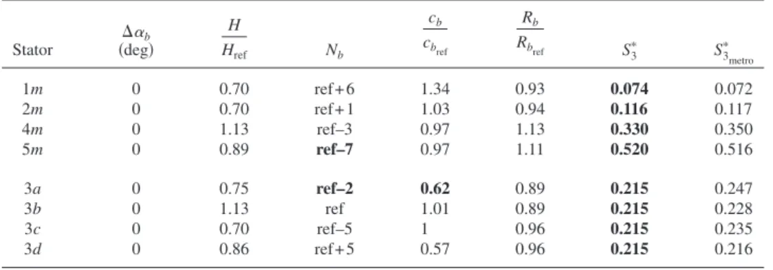
In the two latter groups, one can note that some configurations are rather “exotic.” Both 5m and 3a propose a very small number of blades with/or a small chord. An illustration of these configu-rations is proposed in Fig. 3. A bad guiding of the flow can be there expected. Despite the fact that setting the geometric param-eters to match a given reduced section is not an easy process and does not propose an infinity of possibilities due to construction constraints, those combinations could have been avoided. But, the response of such unreasonable configurations seems interesting to gauge the limitations of the reduced section influence.
The values given in Tables 1 and 2 are the theoretical ones in order to clarify the approach共quoted S3ⴱin the tables兲. A metro-logic verification of the geometries has been conducted after the physical construction of the different stators. A difference in terms of the reduced section has been observed, but in small proportion as the mean deviation between theoretical and real values is around 6% 共the values obtained are presented in the tables as S3
metro
ⴱ 兲. All the results and correlations presented in the forthcom-ing section of course display the real values of the reduced section given by metrology.
3.2 Experimental Device. The test was conducted on our
‘‘Petite TurboMachine’’共PTM兲 test rig dedicated to turbocharger application. This steady flow test rig allows either global or local instrumentation of small stages for a wide range of inlet tempera-tures共from 20°C to 620°C兲 up to 250 g/s. The air is supplied by a pressure source共6 bars兲 stabilized by two regulation stages. The compressor and turbine flows are independent. They are thermally isolated from the ambient air and from one another. A specific circuit supplies hot and pressurized oil to the bearings. Inlet and outlet pressures and temperature are acquired in order to measure the performance of both of the stages. Mass-flow measurement is operated through a Coriolis flowmeter. Rotational speed is counted using a proximity sensor on the compressor stage. For
Fig. 2 Geometric factors of the stator
Table 1 Characteristics of the first group of stators
Stator 共deg兲⌬␣b Hb Hbref S 3 ⴱ 1 ⫺15 1 0.074 2 ⫺10 1 0.116 3共ref兲 0 1 0.215 4 +10 1 0.330 5 +22 1 0.520 ¯ ¯ ¯ ¯ 2s ⫺10 0.71 0.086 3s 0 0.71 0.154 ¯ ¯ ¯ ¯ 4h +10 1.13 0.378 5h +22 1.13 0.596
more details about the test facility, see Ref.关14兴. As the experi-mental study deals with comparative results, it is the repeatability quality of the experimental device that mainly imports. The con-fidence ranges are given in Table 3 for the nondimensional quan-tities mostly considered in the results.
For machining convenance, the prototype stators were built with aluminum alloy共AU4G兲, which does not sustain high tem-peratures. The test was then conducted under ambient temperature for the air flow supplied to the turbine stage. The pressure-ratio lines are described for different values共ts from 1.4 to 1.9兲 by modifying the loading of the compressor controlled by a discharge valve. A minimum of four points per line is acquired. For the reference configuration, the range of the pressure-ratio lines is widened by using compressor impellers of different diameters. The results obtained are now presented.
4 Results
The presentation of the post-treated results is now proposed in three sections according to the three axes identified for the ap-proach. The numerical results for the reduced mass-flow, reduced speed, and efficiency are given as fraction of the values of a reference operating point. This point is located on the pressure-ratio linets= 1.8 for the reference stator共stator 3兲.
4.1 Relative Influence of Stator Height and Opening
Position. Figure 4 presents the evolution of the pressure-ratio
lines obtained with the different stators in the− map. First, the opening angle is the only parameter modified, the height being fixed at the reference value共Fig. 4兲. Second, both of these param-eters are altered共Fig. 5兲. In Fig. 4, the linearity of the pressure-ratio lines is remarkable. This observation strongly supports the theoretical development proposed above. Beside this observation, the influence of the opening position via the reduced section共S3ⴱ兲 on the slope of the lines is confirmed. Now, in Fig. 5, the same mechanism can be observed for a given opening position when changing the stator height: The stator height modification induces an alteration of the value of the reduced section, thus changing the slope of the lines. As fewer points were taken in that configuration due to the small operating range allowed by the compressor, this assessment is not strongly perceptible on the figure. The values of the slope A are thus plotted against the reduced section of the successive stators for a fixed pressure-ratio共ts= 1.8兲 in Fig. 6. A regular decrease is observed. This decrease of A is compared with a theoretical variation 共from Eq. 共3兲, we expect that A⬀共S3ⴱ兲−1兲 with quite good agreement.
Eventually, the functioning trajectory in the− map strongly depends on the value of the reduced section, whatever is the origin of its variation 共stator opening position or blade’s height alter-ation兲, as was predicted by the theory. To illustrate this equiva-lence, Fig. 7 gives a classic representation of the turbine map. For both the small- and the large-height configurations of the blades, the results of the five opening configurations of the stators have
Table 2 Characteristics of the second and third groups of stators
Stator 共deg兲⌬␣b H Href Nb cb cbref Rb Rbref S 3 ⴱ S 3metro ⴱ 1m 0 0.70 ref+ 6 1.34 0.93 0.074 0.072 2m 0 0.70 ref+ 1 1.03 0.94 0.116 0.117 4m 0 1.13 ref–3 0.97 1.13 0.330 0.350 5m 0 0.89 ref–7 0.97 1.11 0.520 0.516 3a 0 0.75 ref–2 0.62 0.89 0.215 0.247 3b 0 1.13 ref 1.01 0.89 0.215 0.228 3c 0 0.70 ref–5 1 0.96 0.215 0.235 3d 0 0.86 ref+ 5 0.57 0.96 0.215 0.216
Fig. 3 Geometries for which a bad guiding of the flow is expected
Table 3 Repeatability uncertainty of the bench
Quantity 95% confidence range 共%兲 Qrt ⫾0.3 Nrt ⫾0.2 ts ⫾0.15 ⫾1 ⫾0.3
⫾1.2 Fig. 4 −map atts= 1.8 for all the opening positions of the
been interpolated to identify the speed-lines and the efficiency-lines for a given compressor loading configuration. This artifi-cially defines two variable-opening stages with different stator heights. The two maps then built are superposed in Fig. 7; the numerical values are given as fraction of the reference operating point. These two maps here present the characteristic features of a variable geometry stage map: a large range of reduced mass-flow for given pressure-ratio and incurved speed-lines reaching a mini-mum pressure-ratio value near the maximini-mum efficiency zone. The two stages do not cover the same regions in the map, but an overlapping zone is observed at the center of the chart. In that zone, a strong correspondence of the two sets of curves is percep-tible. Either the speed-lines or the efficiency-lines are almost su-perimposed from one stage to another, and the isovalue is the same. From this zone, the large-height stage extends to the largest mass-flow values, and the small-height stage to the lesser ones, just as if the two stages were in continuity from one to another. The fraction of this extended map covered by a stage is given by the range of the reduced section that the geometry is able to pro-duce. Obviously, when the reduced section is no more variable, the zone is almost restricted to a single line: It reduces to a classic
fixed geometry turbine map.
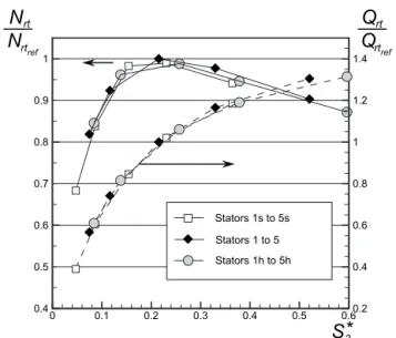
Figure 8 illustrates the importance of the reduced section value in the identification of the overlapping zone between the stages. With S3ⴱandtsfixed, and for a given loading of the compressor, the mass-flow and the rotational speed are identical for the three stages, even if the physical value of opening angle or height is different. An overlapping region is found in the map if the reduced section ranges of the three stages overlap also.
This assessment leads to the conclusion that the two solutions 共opening or height variation兲 are equivalent provided that the technological effects are discarded, which is not the case in real-ity. Basically, the choice to adopt one of the two solutions should be considered through the actual ability to limit the losses associ-ated with one or the other. But, in principle, they are of equivalent validity. The key to the problem is the variation of the reduced section. If the right variation is ensured, the right operating range seems almost guaranteed even if some dispersion in the perfor-mance is observed共efficiency-lines are not strictly superimposed in Fig. 7兲.
Stator opening and height are not the only physical possibilities to interfere with the reduced section value. As explained in the first part of the paper, three more geometric parameters are
in-Fig. 5 −map atts= 1.8 for some combined variations of
stator opening position and stator height
Fig. 6 Variation of the pressure-ratio line’s slope with the value of S3ⴱ 0.80 0.90 1.00 1.00 1.10 1.10 0.60 0.70 0.80 0.90 1.00 1.10 1.4 1.6 1.8 0.4 0.6 0.8 1 1.2
π
Qrt/Qrtref ts 0.66 0.75 0.83 0.91 Speed-lines for large-height stator Speed-lines for small-height stator Efficiency-lines for large-height stator Efficiency-lines for small-height statorFig. 7 Superposition of the map for both high and small stator heights. Numerical values are relative to the reference state.
Fig. 8 Mass-flow and rotational speed evolution against the reduced section forts= 1.8
volved in the definition of S3ⴱ. Thus, there might be, for a given reduced section, an optimal geometric construction. The second step of the approach then brings the other geometric parameters of the stator into the study to confirm the importance of the reduced section and have a first discussion about performance.
4.2 Generalization to Other Parameters. Here, the results
of stators 1m , . . . , 5m are presented. This succession of configu-rations aims at reproducing the behavior of a variable-opening stator without changing opening configuration. All the other pa-rameters 共Hb, cb, Nb, and Rb兲 are thus modified to perform the geometry variation. On the− map of Fig. 9 are plotted the four pressure-ratio lines of the modified configurations compared with the five reference configurations. The linearity is still verified compared with the reference machine even if fewer points were acquired. Configurations 1m, 2m, and 4m are very close to their related initial configuration: The experimental points are almost located on the linear regression obtained for the initial geometry of the stators despite the fact that the opening angle is different. However, configuration 5m is quite different from its original dec-lination. It seems closer to stator 3 rather than stator 5. This kind of result was expected from the very beginning of the study, as we have already pointed out that configuration 5m does not give a proper definition of the interblade channels due to its low number of small blades共as was illustrated in Fig. 3兲. As a result, it is quite difficult to identify a throat and thus an adequate definition of the reduced section. Here, the fact that the result is quite similar to stator 3 better than stator 5 suggests that some phenomenology, most likely separations, reduces the actual geometric value of the reduced section to a lesser effective one. However, without local data, this assumption is purely conjectural. Some computational fluid dynamics共CFD兲 could be most useful in that purpose and is scheduled in forthcoming work.
The slope values of the lines obtained with configurations 1m , . . . , 5m are plotted in the correlation between slope and re-duced section value共see Fig. 10兲. Here, the modified configura-tions merge completely in the trend of what was defined by the variable-opening configurations. It reinforces the predominance of the reduced section value over any geometric factor to define the pressure-ratio line in the− map. Quite logically, configuration 5m is not in the normal evolution and presents a slope higher than what could be expected for reasons explained above.
The results obtained are also compared with what was pre-sented in Fig. 8. In Fig. 11, a best fit evolution has been defined using all the configurations of the first step of the study 共1s,2s, ... ,3, ... ,5h兲; the reference stators’ value has been
ex-plicitly transferred. Here, the pressure-ratio is fixed共ts= 1.8兲 to-gether with the compressor loading configuration. The modified configuration results are thus compared with this expected evolu-tion. The result speaks for itself either for rotational speed or for the reduced mass-flow. Except for configuration 5m, the modified stators describe accurately the expected evolution. In other words, whatever the geometric factor choice to perform geometry varia-tion, as long as the reduced section value is kept constant, the stage behavior is not strongly affected. However, the question of efficiency is raised. Figure 12 presents the evolution of the total-to-static isentropic efficiency against mass-flow for the reference and the modified configurations at the fixed pressure-ratio. The configurations presented on the first part of the paper were also plotted. Once again, the modified configuration follows the ex-pected trend. The typical deviation compared with the reference configuration is completely in the range of what was observed when changing the stator blades and height. It confirms the fact that the choice of the geometric parameter operating the geometry variation is not such an important choice from a theoretical point of view. It is the value of the reduced section that defines the
Fig. 9 Equivalence in the − map of initial and modified
configurations forts= 1.8 Fig. 10 Pressure-ratio line’s slope of the modified configurations
Fig. 11 Reproduction of the variable geometry behavior with-out opening-configuration modification
operating point and an order of magnitude for the performance for a given pressure-ratio and a given loading configuration of the compressor. However, we can observe that some configurations give better results than others. For example, stator 2m proves more efficient than the reference geometry. This means that be-sides the obtention of a given operating point, some latitude for improvement is available. Surprisingly, configuration 5m is defi-nitely integrated to the evolution, but not at the expected location: The results are very similar to those of a lower reduced section configuration, which once again points out that some blockage must occur.
We have then proved that the value of the reduced section de-fines the operating point for a given pressure-ratio. This is true provided that the stator has a “reasonable” construction 共i.e., a good guidance of the flow is supplied by the stator blades兲. How-ever, quite logically, some variations in the performance for given S3ⴱhave been observed. It leads to focus on the influence of the geometric construction on the efficiency of a given reduced sec-tion. This analysis is now performed.
4.3 Importance of Geometric Construction. Even if the
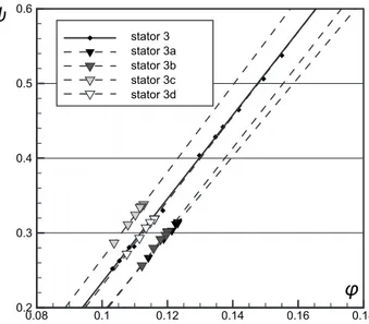
re-duced section defines the operating point, we have shown above that it does not constrain efficiency. For a given value of S3ⴱ, dif-ferent geometric configurations are possible to design, but are not equivalent in terms of performance. This dependence of the effi-ciency to the geometric construction is due in part to the complex local process of rotor/stator interaction, difficult to apprehend and beyond the scope of this paper. However, some observations can be made. The stators 3a , . . . , 3d have been designed in order to present the same value of S3ⴱ as the reference configuration. The same stage behavior is then expected from all of these configura-tions. In Fig. 13 are presented the results of the stators in the − map compared with the reference stator at ts= 1.8. The evo-lution is still linear for each of the configurations. The slope of the line is quite the same as the different lines are almost perfectly parallel to the reference stator line. However, an offset is observed between the evolutions.
The stage behavior is presented by using the usual indicators in Fig. 14. The variations of reduced mass-flow and rotational speed against the pressure-ratio display a deviation between the different configurations. It is very small regarding the rotational speed共less than 2%兲, but the mass-flow differs by ⫾5% compared with the reference configuration. Here, the metrologic control of the geom-etries has proved useful, as it revealed the fact that the actual reduced section of configuration 3a was slightly greater than the
reference configuration, as was presented in Table 2. The differ-ence of geometry should explain most of the deviation. But, the possibility of interference of the geometric construction on some local phenomenology exists. For example, configuration 3c is close to the reference stator in terms of the actual value of the reduced section and still presents a deviation in the mass-flow value, which is not fully understood.
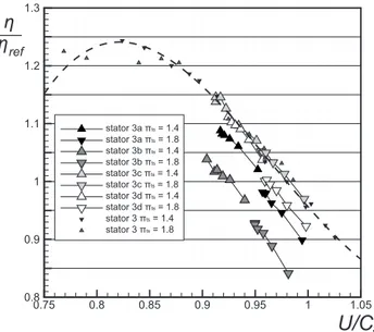
However, beside the exact reproduction of the operating point, the evolution of efficiency is most interesting. In Fig. 15 is pre-sented the evolution of the efficiency against the reduced tip-speed for the four declinations of the reference stator compared with the reference geometry共a polynomial interpolation has been operated for the reference stator兲. Two pressure-ratio lines are considered 共ts= 1.4 and 1.8兲 for each configuration. Two main observations are retained: First, the two pressure- ratio lines are almost in continuity from one to another in this diagram, whatever the configuration considered. This is the expression of the impor-tant correlation between reduced tip-speed and efficiency for ra-dial turbine stages. This has been widely presented and explained in the literature with the well known optimum found around U/Cs= 0.7. In fact, a lot of prediction process makes the
assump-tion of the unicity of this evoluassump-tion for a given stage in order to
Fig. 12 Efficiency evolution with the mass-flow forts= 1.8
Fig. 13 −map atts= 1.8 for the different geometries
hav-ing the same reduced section value„3a, . . . ,3d…
1.3 1.4 1.5 1.6 1.7 1.8 1.9 2 0.7 0.8 0.9 1 1.1 1.2 1.3 0.5 0.6 0.7 0.8 0.9 1 1.1
Qrt
Qrt
reN
N
rtrtref stator 3 stator 3a stator 3b stator 3c stator 3dπ
tsFig. 14 Mass-flow and rotational speed evolutions against the pressure-ratio value
obtain the order of magnitude of efficiency. The second observa-tion is the clear hierarchy between the configuraobserva-tions. Configura-tion 3c is a match for the reference configuraConfigura-tion and configura-tion 3b clearly presents the worst performance. The explanaconfigura-tion of this difference cannot be simple since it is an expression of the complex physical phenomenon occurring between the rotor and the stator. Choosing a global indicator expressing local behavior in order to classify the configurations is thus challenging. One choice is the free space parameter found in Ref.关15兴 whose ex-pression is recalled in Eq.共7兲,
⌬Rⴱ= R3− R4
H cos共␣3兲 共7兲
This indicator is a nondimensional expression of a trajectory esti-mation of the particles in the free space between the stator and the rotor. An optimum was observed and reputed to be found around ⌬Rⴱ= 2. It is obvious that this criterion will not allow to take into account the full complexity of the loss process occurring in the real flow, but has the advantage to be built with data available at the very beginning of the design process. A correlation between the performance of the different configurations and the free space parameter is proposed in Fig. 16. A global trend is observed,
reaching an optimum almost centered on 2, for two different val-ues of the pressure-ratio. But, the fact that few geometries were tested and the range of⌬Rⴱbeing restrictive does not allow to be strictly conclusive about the relevance of the parameter. More specifically, one can note the deviation of configuration 3d from the trend, which appends to be the configuration having the most important number of blades. It thus leads to consider the necessity of other criteria describing the performance potential of a given geometry, as it is needed in the classic stator design. But, it must be reminded that in the variable geometry context, some choices appearing good for a given position of the nozzle can prove di-sastrous for another one. Finally, the choice of the design nozzle-position has as much importance as the design itself.
5 Conclusion
Both theoretical and experimental analyses have been con-ducted in order to understand the variable geometry process in radial turbines. The use of an alternative to the usual turbine map eases the understanding of such an effect, highlighting the nondi-mensional section of the stator as a key parameter to the problem. Based on the presumed importance of this reduced section in the variable geometry process, a specific approach involving the ex-tensive variation of parameters of the geometry has been built, and tests were conducted. The results allowed discussing the state-ments expressed at the beginning of the paper. Summarizing, we have shown the following.
1. From a theoretical point of view, yes, both the solutions found in the industry for variable geometry stages共variable opening or variable height兲 are equivalent, but are not in reality because some technological drawbacks are unavoid-able.
2. Yes, it is possible to reproduce the exact behavior of a variable-opening stator without changing the stator opening angle.
3. Two configurations with different geometric configurations but with the same value of reduced section tend to behave the same way.
Some divergence from the expected behavior, predicted by the theory, was observed. Some of those divergence were due to a perfectible conformity of the geometry built, but other were inher-ent to the stage functioning. This was expectable as the complex tridimensional flow occurring in the stage cannot be completely modeled by a one-dimensional approach. Even if they proved of a small order of magnitude, those divergence need more local data in the stator region to deepen the analysis. But, small divergence can have dramatic consequences on the efficiency of a stage. In that field, we presented the free space criterion as a good candi-date to apprehend the performance potential of a geometry for a given reduced section value. Other criteria exist and should be gathered from the literature focused on the design process of the stator. In the author’s view, the right combination of them is prob-ably necessary to propose adequate correlations. A judicious para-metric study at constant reduced section could also precise these correlations since the geometric factors constituting the stator should be classified in importance. Anyway, some part of the op-erating range of a variable geometry stage can be favored com-pared to other ones, since it might not be possible to match the proper design criteria for all of the stator positions. This should be taken into account in the very first steps of the design process, and not analyzed subsequently.
Nomenclature
Roman
A ⫽ gradient of the pressure-ratio lines Cb ⫽ chord of the blades
Cs ⫽ isentropic speed 0.75 0.8 0.85 0.9 0.95 1 1.05 0.8 0.9 1 1.1 1.2 1.3 stator 3a πts= 1.4 stator 3a πts= 1.8 stator 3b πts= 1.4 stator 3b πts= 1.8 stator 3c πts= 1.4 stator 3c πts= 1.8 stator 3d πts= 1.4 stator 3d πts= 1.8 stator 3 πts= 1.4 stator 3 πts= 1.8
η
η
ref sU/C
Fig. 15 Efficiency evolution against the reduced tip-speed0.6 0.8 1 1.2 1.4 1.6 1.8 2 2.2 2.4 0.8 0.9 1 1.1 1.2
η
η
ref∆R
* stator 3a stator 3b stator 3c stator 3d stator 3 π = 1.4 π = 1.8 ts tsD ⫽ diameter H ⫽ enthalpy m˙ ⫽ mass flow rate Nb ⫽ number of blades
Nrt ⫽ nondimensional rotational speed P ⫽ pressure
Qrt ⫽ nondimensional mass flow rate R ⫽ radius
S ⫽ geometric cross-section area Sⴱ ⫽ reduced cross-section area
U ⫽ tip-speed
Greek
␣ ⫽ absolute flow angle ␣b ⫽ opening angle of the blades
 ⫽ relative flow angle ␥ ⫽ specific heat ratio ⫽ efficiency ⫽ intermediate pressure-ratio ⫽ pressure-ratio ⫽ density ⫽ flow coefficient ⫽ loading coefficient Subscripts 3 ⫽ stator outlet 4 ⫽ rotor inlet 5 ⫽ rotor outlet ts ⫽ total-to-static state ref ⫽ reference state References
关1兴 Baines, N. C., and Lavy, M., 1990, “Flows in Vaned and Vaneless Stators of
Radial Inflow Turbocharger Turbines,” IMech Paper No. C405/005. 关2兴 Spence, S., Rosborough, R., Artt, D., and McCullough, G., 2007, “A Direct
Performance Comparison of Vaned and Vaneless Stators for Radial Turbines,” ASME J. Turbomach., 129共1兲, pp. 53–61.
关3兴 Lakshminarayana, B., 1996, Fluid Dynamics and Heat Transfers of
Turboma-chinery, Wiley Interscience, New York.
关4兴 Chappie, P. M., Flynn, P. R., and Mulloy, J., 1980, “Aerodynamic Design of Fixed and Variable Geometry Nozzleless Turbine Casings,” ASME J. Eng. Power, 102共1兲, pp. 141–147.
关5兴 Baines, N. C., 2005, Fundamentals of Turbocharging, Concepts ETI. 关6兴 Meitner, P. L., and Glassman, A. J., 1980, “Loss Model for Off-Design
Per-formance Analysis of Radial Turbines With Pivoting-Vane, Variable-Area Sta-tors,” SAE Technical Paper No. 801135.10.4271/801135
关7兴 Qiu, X., Anderson, M. R., and Baines, N. C., 2009, “Meanline Modeling of Radial Inflow Turbine With Variable Area Nozzle,” ASME Paper No. GT2009-59170.
关8兴 Fukaya, M., and Watanabe, A., 2000, “Compressible Turbulent Flow Analysis on Variable Nozzle Vane and Spacers in Turbochargers Turbine,” SAE Tech-nical Paper Series 2000-01-0526.
关9兴 Binder, N., Carbonneau, X., and Chassaing, P., 2004, “Volute Outlet Condi-tions Study by Measurements on the Stator Blades of a Small Dimension Radial Turbine Stage,” Third International Conference on Heat Transfer, Fluid Mechanics and Thermodynamics.
关10兴 Moustapha, H., Zeleski, M. F., Baines, N., and Japikse, D., 2003, Axial and
Radial Turbines, Concepts ETI.
关11兴 Zhang, J., Zhuge, W., Hu, L., and Li, S., 2007, “Design of Turbocharger Variable Nozzle,” Proceedings of the ASME Turbo Expo 2007, Montreal, QC, Canada.
关12兴 Binder, N., Carbonneau, X., and Chassaing, P., 2008, “Off-Design Consider-ation Through the Properties of Some Pressure-Ratio Line of Radial Inflow Turbines,” Int. J. Rotating Mach., 2008, p. 273296.
关13兴 Carbonneau, X., and Binder, N., 2009, “Analysis of the Pressure-Ratio Lines for Radial Turbines,” Proceedings of the Eighth European Turbomachinery
Conference (ETC 8).
关14兴 Binder, N., Carbonneau, X., and Chassaing, P., 2005, “Influence of a Variable Guide Vane Nozzle on the Design Parameters of a Radial Turbine Stage,”
Proceedings of the ETC 2005, Lille, France.
关15兴 Watanabe, I., Ariga, I., and Mashimo, T., 1971, “Effect of Dimensional Param-eters of Impellers on Performance Characteristics of a Radial Inflow Turbine,” ASME J. Eng. Power, 93共1兲, pp. 81–102.