UNIVERSITÉ DE SHERBROOKE Faculté de génie
Département de génie Mécanique
OPTIMISATION DE TRANSDUCTEURS
PIÉZOÉLECTRIQUES POUR LA GÉNÉRATION
D’ONDES GUIDÉES
Thèse de doctorat Spécialité : génie mécanique
Peyman YAZDANPANAH MOGHADAM
Jury : Patrice MASSON (directeur) Nicolas QUAEGEBEUR Ahmed MASLOUHI Pierre BÉLANGER
To my father, Ali, my mother, Akram, my brother, Ehsan, all my teachers, family and close friends who have always supported and encouraged me in my life to continue my education in the name of freedom and humanity.
i
RÉSUMÉ
Les systèmes de surveillance de santé structurale sont proposés pour la détection d’endommagement dans les infrastructures qui dépassent leur durée de vie en utilisant les ondes guidées (GW). Les ondes guidées peuvent parcourir de longues distances et sont sensibles à une variété d’imperfections. Les transducteurs piézoélectriques sont communément utilisés pour générer et mesurer les ondes guidées dans des structures minces. Comme la détection du défaut et sa localisation sont souhaitées, la nature de la génération des ondes guidées sous forme de plusieurs modes implique une complexité supérieure dans le traitement du signal. Pour remédier à cette limitation, une nouvelle méthode est présentée ici pour la génération des ondes guidées par sélection de mode, et un nouveau transducteur piézoélectrique est ensuite conçu, fabriqué et testé.
Tout d'abord, la génération des ondes guidées par optimisation systématique du profil interfacial de la contrainte de cisaillement en mode sélectif est étudiée. En utilisant le principe de superposition, une méthode d'analyse est d'abord développée pour la modélisation de la génération des ondes guidées par un nombre fini de segments de contrainte de cisaillement uniforme, chacun contribuant à un profil élémentaire d’une contrainte constante de cisaillement. Sur cette base, deux fonctions coût sont définies afin de minimiser les modes indésirables et amplifier le mode sélectionné et le problème d'optimisation est résolu avec un cadre d'optimisation d’algorithme génétique parallèle. Les avantages de cette méthode par rapport à d'autres approches de conception de transducteurs classiques sont (1) la contrainte de cisaillement peut être explicitement optimisée à la fois pour exciter un mode et supprimer d'autres modes indésirables, (2) la taille de la zone d'excitation n’est pas limitée et l’excitation en mode sélectif est toujours possible, même si la largeur d'excitation est inférieure à toutes les longueurs d'onde excitées, et (3) la sélectivité est accrue et la largeur de bande est étendue. La méthode analytique et les fonctions coût sont ensuite développées pour concevoir un transducteur piézoélectrique à éléments multiples (MEPT) simple et performant. Une méthode numérique est tout d'abord mise au point pour extraire la contrainte interfaciale entre un seul élément piézocéramique et une structure d'accueil et ensuite utilisée comme entrée d'un modèle analytique pour prédire la propagation des ondes guidées à travers l'épaisseur d'une plaque isotrope. Deux nouvelles fonctions coût sont proposées pour optimiser la contrainte de cisaillement interfaciale pour supprimer le(s) mode(s) indésirable(s) et maximiser un mode désiré. Simplicité et faible coût de fabrication sont deux principales cibles visées dan la conception du MEPT. Un prototype TPEM est ensuite fabriqué à l'aide de micro-usinage laser. Une procédure expérimentale est présentée afin de valider les performances de la TPEM comme une nouvelle solution pour la génération des ondes guidées en mode sélectif. Des essais expérimentaux illustrent la forte capacité du TPEM pour la génération des ondes guidées en mode sélectif, puisque le mode indésirable est supprimé par un facteur allant jusqu'à 170 fois par rapport aux résultats obtenus avec un seul piézocéramique.
Mots-clés: Surveillance de santé structurale, ondes guidées, transducteur piézoélectrique à
ii
ASTRACT
Structural Health Monitoring (SHM) systems are being proposed for damage detection of infrastructures that exceed their life using ultrasonic Guided waves (GWs). GWs can travel over long distances and are sensitive to variety of defects. Piezoelectric transducers (PZTs) are commonly used to generate and measure GWs in plate-like structures. As damage detection and localization is sought, the multi-mode nature of GW generation involves higher complexity in signal processing. To overcome this limitation, a new method is presented here for mode-selective GW generation, and a novel mode-mode-selective PZT is then designed, manufactured and tested.
First, mode-selective generation of GWs by systematic optimization of the interfacial shear stress profile is investigated. Using the superposition principle, an analytical method is first developed for modeling GWs generation by a finite number of uniform shear stress segments, each contributing with a constant elementary shear stress profile. Based on this, two cost functions are defined in order to minimize the undesired modes and amplify the selected mode and the optimization problem is solved with a parallel Genetic Algorithm (GA) optimization framework. Advantages of this method over more conventional transducers tuning approaches are that (1) the shear stress can be explicitly optimized to both excite one mode and suppress other undesired modes, (2) the size of the excitation area is not constrained and mode-selective excitation is still possible even if excitation width is smaller than all excited wavelengths, and (3) the selectivity is increased and the bandwidth extended.
The analytical method and objective functions are then developed to design a novel and cost-effective multi-element piezoelectric transducer (MEPT). A numerical method is first developed to extract the interfacial stress between a single piezoceramic element and a host structure and then used as the input of an analytical model to predict the GW propagation through the thickness of an isotropic plate. Two novel objective functions are proposed to optimize the interfacial shear stress for both suppressing unwanted mode(s) and maximizing a desired mode. Simplicity and low manufacturing cost are two main targets driving the design of the MEPT. A prototype MEPT is then manufactured using laser micro-machining. An experimental procedure is presented to validate the performances of the MEPT as a new solution for mode-selective GW generation. Experimental tests illustrate the high capability of the MEPT for mode-selective GW generation, as unwanted mode is suppressed by a factor up to 170 times compared with the results obtained with a single piezoceramic.
Keywords : Structural Health Monitoring, Guided waves, multi-element piezoelectric
iii
ACKNOWLEDGMENTS
I would like to say thank you to my supervisor Prof. Patrice Masson for all his support and consideration. It has been a great honor for me to be your student. Under your supervision, I learned how to work professionally. Thank you for helping me to become a mature researcher. You never let me down; instead you helped me get things better. Thank you very much.
I would like to say thank you to my colleague, Nicolas Quaegebeur, for all his professional support. Nicolas, thank you for sharing your knowledge and experience in SHM with me. Thank you very much.
I would like to say thank you to all my colleagues in SHM team at the GAUS, Kyle Mulligan and Pierre-Claude Ostiguy, for sharing their knowledge and expertise on simulation and experimental tests to support this project.
I would like to say thank you to my parents and my brother for all their support. I learned from my parents that humanity and honesty should be always first priorities of my life.
From all my friends, I wish to especially thank Mr. Javad Ensmaelpanah and Mr. Ehsan Masouni who instead to remain anonymous for being true friends.
This study has been conducted with the financial support from the Natural Sciences and Engineering Research Council of Canada (NSERC).
iv
TABLE OF CONTENTS
CHAPTER 1 ... 1 INTRODUCTION... 1 1.1 Problem statement ... 2 1.2 Objectives ... 2 1.3 Originality ... 3 1.4 Thesis outline ... 4 CHAPTER 2 ... 6 Literature review ... 62.1 Structural Health Monitoring (SHM) ... 7
2.2 NDT and SHM systems ... 9
2.3 Damage detection using GWs ... 10
2.3.1 GWs propagation in plate-like structures ... 11
2.3.2 GW mode selection ... 13
2.4 Piezoelectric transducers ... 14
2.4.1 Monolithic piezoelectric transducers ... 15
2.4.2 Ring and circular piezoelectric transducer ... 17
2.4.3 Interdigital transducer (IDT) ... 19
2.4.4 Phased array transducer ... 24
2.4.5 Micro-Fiber-Composite (MFC) ... 26
2.4.6 Wedge angle transducer ... 27
2.4.7 Tilted angle polarization type piezoelectric transducer (TAPP) ... 29
2.4.8 Electromagnetic acoustic transducer (EMAT) ... 30
2.4.9 Composite long-rang variable-direction emitting radar (CLoVER) ... 32
2.4.10 Frequency steerable acoustic transducer (FSAT) ... 33
2.5 Modeling of GW generation ... 34
2.6 Optimization of piezoelectric transducers ... 39
2.6.1 Genetic Algorithm (GA) ... 40
2.6.2 Artificial Neural Network (ANN) ... 41
2.6.3 Other popular optimization methods in SHM ... 41
CHAPTER 3 ... 44
MODE SELECTIVE GENERATION OF GUIDED WAVES BY SYSTEMATIC OPTIMIZATION OF THE INTERFACIAL SHEAR STRESS PROFILE ... 44
3.1 Contribution summary ... 45
3.2 Abstract ... 45
3.3 Introduction ... 46
3.4 Methodology ... 50
v
3.4.2 Optimal shear stress profile determination ... 55
3.4.3 Parameters of the optimization process ... 57
3.5 Validation of the optimization process ... 58
3.5.1 Application ... 58
3.5.2 Results ... 60
3.5.2.1 Convergence of the optimization process ... 60
3.5.2.2 Optimal shear stress profile ... 62
3.5.3. Discussion... 67
3.6 Conclusion ... 68
CHAPTER 4 ... 69
DESIGN AND OPTIMIZATION OF A MULTI-ELEMENT PIEZOELECTRIC TRANSDUCER FOR MODE-SELECTIVE GENERATION OF GUIDED WAVES ... 69
4.1 Contribution Summary ... 70
4.2 Abstract ... 70
4.3 Introduction ... 71
4.4 METHODOLOGY ... 74
4.4.1 Modeling GW generation ... 74
4.4.1.1 FEM modeling and interfacial shear stress extraction ... 74
4.4.1.2 Analytical solution of GW propagated from the MEPT ... 76
4.4.2 Optimization approach ... 78
4.4.2.1 Parameters ... 78
4.4.2.2 Objective functions ... 78
4.5 Design and Performance Validation ... 80
4.5.1 Manufacturing constraints of the MEPT ... 82
4.5.2 Design parameters of the MEPT ... 82
4.5.3 Optimal Interfacial Shear Stress ... 85
4.5.4 Experimental Setup ... 86
4.5.5 Experimental correction factors ... 86
4.5.6 Mode-selective GW excitation ... 88 4.6 Conclusion ... 93 4.7 Ackowledgement ... 93 CHAPTER 5 ... 94 CONCLUSION ... 94 5.1 Discussion ... 94
5.2 Originality of the Work ... 95
5.3 Limitations and future work ... 95
APPENDIX A ... 97
MICRO-MACHINING WITH THE LPKF PROTOLASER U3 ... 97
A.1 Minimal Requirements, High Performance ... 97
A.2 Broad Range of Materials ... 97
A.3 Advantages of Laser Processing ... 97
A.4 Impressive Results with the LPKF ProtoLaser U3 ... 98
viii
LIST OF FIGURES
FIGURE 2. 1 HUMAN NEURAL NETWORK CONCEPT IN STRUCTURAL HEALTH MONITORING OF
AIRCRAFT STRUCTURE (TRILAKSONO ET AL., 2013). ... 8
FIGURE 2. 2 VARIATION OF DAMAGE DELECTABILITY VERSUS SENSOR SIZE FOR THE COMMON SHM TECHNIQUES IN THE CASE OF A COMPOSITE PANEL OF 1 M × 1 M. FOR EACH TECHNIQUE, THE DETECTION IS EFFECTIVE LOCALLY (L), ON THE HALF PLATE (H) OR ON THE ENTIRE PLATE (E). THE ONLY RELIABLE TECHNIQUES ON THE ENTIRE STRUCTURE ARE GW AND MODAL ANALYSIS (SETH STOVACK KESSLER, 2002). ... 10
FIGURE 2.3BULK WAVE GENERATION WITH A BONDED PZT.LONGITUDINAL AND SHEAR WAVES ARE GENERATED IN THE PLATE. ... 11
FIGURE 2. 4 SYMMETRIC AND ANTI-SYMMETRIC GW MODES (SU, YE, & LU, 2006). ... 13
FIGURE 2. 5 (A) PHASE VELOCITY DISPERSION CURVES FOR A 2 MM THICK ALUMINUM PLATE. (B) GROUP VELOCITY DISPERSION CURVES FOR A 2 MM THICK ALUMINUM PLATE (WAN, ZHANG, XU, & TSE, 2014). ... 13
FIGURE 2. 6 V13 DENOTES A RESPONSE MEASURED BY THE INNER CIRCULAR PART OF THE SENSING PZT WHEN BOTH THE OUTER RING AND THE INNER CIRCULAR PARTS OF THE EXCITATION PZT ARE ACTIVATED. (HERE, THE SUBSCRIPTS, 1, 2 AND 3 DENOTE THE ENTIRE DUAL PZT, THE OUTER RING PZT AND THE INNER CIRCULAR PZT, RESPECTIVELY.) THE DARKER AREA OF THE DUAL PZT REPRESENTS THE PZT COMPONENT(S) ACTIVATED EITHER FOR EXCITATION OR SENSING (YEUM ET AL., 2011). ... 18
FIGURE 2. 7 ELASTIC PLATE WITH PIEZOELECTRIC ACTUATORS (EV GLUSHKOV ET AL., 2010). .... 19
FIGURE 2. 8 PLANE VIEW AND CROSS SECTION OF THE IDT TRANSDUCER (MONKHOUSE ET AL., 2000). ... 20
FIGURE 2. 9 TYPICAL TRANSDUCER ELECTRODE PATTERNS FOR Λ = 2.4 MM (A) PLAIN; (B) APODISED (MONKHOUSE ET AL., 1997). ... 21
FIGURE 2.10600 RADIAL TRANSDUCER (MONKHOUSE ET AL.,2000). ... 22
FIGURE 2. 11 SCHEMATIC DESIGN OF AN IDT WITH APODIZATION (SCHMIDT ET AL., 2013). ... 23
FIGURE 2. 12 MAX. AMPLITUDE OF A0 AND S0 MODE AT DIFFERENT ELECTRODE WIDTHS, ACTUATOR WITH 7 ELECTRODES,40 KHZ,2 MM THICK CFRP PLATE (SCHMIDT ET AL.,2013). ... 24
FIGURE 2. 13 A TIME-DELAY SYSTEM WITH PULSE (PHYSICAL) DELAYS AND SOFTWARE DELAYS FOR A TRANSDUCER ARRAYS (J. LI & ROSE, 2001). ... 25
FIGURE 2. 14 ILLUSTRATION OF A PHASED ANNULAR ARRAY WITH A TIME DELAY DT APPLIED BETWEEN EACH ADJACENT ARRAY ELEMENTS (YAN, BORIGO, LIANG, KODURU, & ROSE, 2011). ... 25
FIGURE 2. 15 MACRO-FIBER COMPOSITE TRANSDUCER (TYPE P2) WITH GEOMETRICAL REFERENCE (MATT & DI SCALEA,2007). ... 26
FIGURE 2. 16 GEOMETRY OF THE FINITE ELEMENT MODEL IN ABAQUS (S LI & CLIFF, 2011). ... 27
FIGURE 2. 15 EXPERIMENTAL SYSTEM (IMANO, 2007). ... 30
FIGURE 2.18CONCEPT OF A TRIAL EMAT(MURAYAMA &MIZUTANI,2002). ... 31
FIGURE 2. 19 ILLUSTRATION OF THE CLOVER TRANSDUCER (K. SALAS & C. CESNIK, 2010). ... 32
FIGURE 2. 20 ELECTRODE DESIGN USED IN FIRST GENERATION OF CLOVER SECTORS (SALAS & CESNIK,2009). ... 33
ix
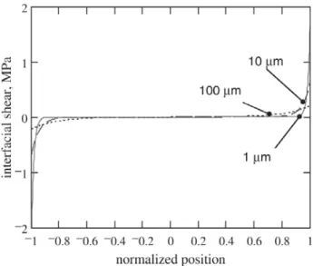
FIGURE 2. 21 SCHEMATIC OF ELECTRODE PATTERNING OF FSAT (BARAVELLI ET AL., 2011). ... 34 FIGURE 2. 22 VARIATION OF SHEAR LAG TRANSFER MECHANISM WITH BOND THICKNESS FOR A
APC-850 PZT (EA = 63 GPA, TA = 0.2 MM, L = 7 MM, D31= -175 MM/KV) ATTACHED TO A THIN-WALL AL STRUCTURE (E=70GPA AND T =1MM) THROUGH A BOND LAYER OF GB=2
GPA (GIURGIUTIU & BOTTAI-SANTONI, 2009). ... 35 FIGURE 2. 23 DECOMPOSITION OF THE BOUNDARY CONDITIONS INTO SYMMETRIC AND
ANTI-SYMMETRIC PARTS (VON ENDE &LAMMERING,2007). ... 36 FIGURE 2. 24 PLOTS VARIATION OF A WITH FREQUENCY-THICKNESS PRODUCTS FOR S0 AND A0
-MODES (GIURGIUTIU & BOTTAI-SANTONI, 2009). ... 38 FIGURE 3. 1 COMPARISON OF CLASSICAL ACTUATOR DESIGN MODELS FOR PZT TRANSDUCERS
USING THE PIN-FORCE ASSUMPTION (A, B) WITH POSSIBLE ACTUATOR DESIGN USING PARALLEL POLARIZATION DIRECTIONS (C), WITH THE CAPABILITY OF CONTROLLING INDIVIDUAL
ELEMENTS (D). ... 47 FIGURE 3.2DESCRIPTION OF THE GEOMETRY AND ARBITRARY SYMMETRIC SHEAR STRESS PROFILE
USED IN THE STUDY. ... 51 FIGURE 3. 3 VARIATION OF NORMALIZED EXCITATION TERM ERROR! OBJECTS CANNOT BE CREATED
FROM EDITING FIELD CODES.FOR DIFFERENT WITH RESPECT TO SEGMENT WIDTH ERROR!
OBJECTS CANNOT BE CREATED FROM EDITING FIELD CODES. FOR BOTH A0 AND S0-MODES. .. 54 FIGURE 3. 4 CONVERGENCE OF OBJECTIVE FUNCTION BASED ON NUMBER OF SEGMENTS N FOR (A) R
= 0.01 M (CASE III), (B) R = 0.04 M (CASE II), (C) R = 0.1 (CASE I) FOR BOTH A0AND S0 -MODES. THE VERTICAL BARS INDICATE THE SIZE OF ONE SEGMENT IN RELATION TO MODAL WAVELENGTH FOR SPECIFIC N VALUES. ... 59 FIGURE 3. 5 REAL (LEFT) AND IMAGINARY (RIGHT) PARTS OF THE OPTIMAL SHEAR STRESS AFTER
MINIMIZATION IN THE CASE III R =0.1 M (A, B), CASE II R = 0.04 M (C, D), CASE I R =0.01 M (E, F), AND PIN FORCE MODEL CASE IV R = 13.5 MM (G) FOR SELECTIVE S0-MODE EXCITATION AT 100 KHZ USING N =35 SEGMENTS. ... 60 FIGURE 3.6REAL (LEFT) AND IMAGINARY (RIGHT) PARTS OF THE OPTIMAL SHEAR STRESS AFTER
MINIMIZATION IN THE CASE III R = 0.1 M (A, B), CASE II R = 0.04 M (C, D), CASE I R = 0.01 M (E, F), AND PIN FORCE MODEL CASE IV R = 3.2 MM MM (G) FOR SELECTIVE A0-MODE EXCITATION AT 100 KHZ USING N =35 SEGMENTS. ... 61 FIGURE 3. 7 MAGNITUDE OF THE SPATIAL FOURIER TRANSFORM OF THE SHEAR-STRESS PROFILE AS
A FUNCTION OF WAVENUMBER (K) FOR SELECTIVE S0-MODE GENERATION IN THE CASES I (A), II (B), III (C) AND IV (D)... 63 FIGURE 3. 8 MAGNITUDE OF THE SPATIAL FOURIER TRANSFORM OF THE SHEAR-STRESS PROFILE AS
A FUNCTION OF WAVENUMBER (K) FOR SELECTIVE A0-MODE GENERATION IN THE CASES I (A), II (B), III (C) AND IV (D)... 65 FIGURE 3.9EVOLUTION OF THE WAVENUMBER VERSUS FREQUENCY FOR A0 AND S0-MODES.THE
BANDWIDTH OF (A) S0-MODE AND (B) A0-MODE GENERATED BY OPTIMAL SHEAR STRESS PROFILES ARE INDICATED USING DASHED LINES. ... 66 FIGURE 4.12D SCHEMATIC OF ARRAY OF N PZT ELEMENTS BONDED ON A PLATE USED FOR FEM.
... 75 FIGURE 4. 2 ABSOLUTE VALUE OF INTERFACIAL SHEAR STRESS DISTRIBUTION OVER EXCITATION
AREA |X| < R WHEN ONLY ELEMENT NUMBER TWO (E2) IS EXCITED AT FREQUENCIES (A) 100
KHZ AND (B) 500 KHZ. ... 75 FIGURE 4. 3 PROPOSED CONCEPT FOR THE MULTI-ELEMENT PIEZOELECTRIC TRANSDUCER (MEPT)
x
STRESS, AND NON-EXCITED AREAS TO KEEP PARALLELISM BETWEEN THE ELEMENTS. ... 81 FIGURE 4. 4 CONVERGENCE STUDY OF OBJECTIVE FUNCTION OF DESIRED MODE WITH RESPECT TO
THE NUMBER OF ELEMENTS AT 100 KHZ AND 500 KHZ. ... 83 FIGURE 4.5SCHEMATIC OF EXPERIMENTAL SET UP TO EXCITE THE MEPT’S ELEMENTS FOR MODE
-SELECTIVE GW GENERATION. ... 85 FIGURE 4. 6 IN-PLANE AND OUT-OF-PLANE AMPLITUDE OF THE SPATIAL FOURIER TRANSFORM OF
PROPAGATED GW BY EACH ELEMENT (E) OF THE MEPT AS A FUNCTION OF WAVENUMBER AT 300 KHZ. ... 87 FIGURE 4. 7 COMPARISON OF X AND Z COMPONENTS AMPLITUDE VELOCITY OF PROPAGATED GW
FROM THE MEPT (SOLID LINE) AND A SINGLE ELEMENT PZT (DOTTED LINE) FOR A0 AND S0 -MODES AT THE DRIVING FREQUENCY... 92 FIGURE A. 1 THE LPKF PROTOLASER U3 ... 98
xii
LIST OF TABLES
TABLE 2. 1 AVAILABLE TECHNIQUES FOR TYPICAL SHM SYSTEMS. ... 9 TABLE 2. 2 OPTIMIZATION PROBLEM TYPES (BADER, 2009) ... 40 TABLE 3. 1 PARAMETERS AND OPERATORS OF THE GA PROCESS. ... 58 TABLE 3.2POWER FLOW RATIOS OF DESIRED MODE TO UNDESIRED MODE USING GA OPTIMIZATION PROCESESS. ... 64 TABLE 4. 1 PARAMETERS AND OPERATORS OF THE GA. ... 80 TABLE 4. 2 EXPERIMENTAL DRIVING FREQUENCIES, WAVELENGTHS AND WAVENUMBERS. ... 81 TABLE 4. 3 OPTIMAL AMPLITUDE Α (V) AND PHASE Φ0 OF INPUT HARMONIC EXCITATION SIGNAL TO
EACH ELEMENT OF MEPT FOR MODE-SELECTIVE EXCITATION IN A 1.6 MM THICK ALUMINUM PLATE. ... 84 TABLE 4. 4 CONTRIBUTION FACTOR FOR EACH ELEMENT FOR SELECTIVE A0 AND S0-MODE
GENERATION AT DRIVING FREQUENCY. ... 87 TABLE A. 1. THE TECHNICAL DATA OF THE LPKT PROTOLASER U3 ... 99 TABLE A.2OPTIMAL ADJUSTMENTS FOR A MICRO-MACHINING ON A PZT-5A OF THICKNESS
xiv
LIST OF SYMBOLS
Symbols Definition
i
α Complex correction coefficient corresponding to element i Α Amplitude of input harmonic excitation signal
a PZT element width p c Phase velocity g c Group velocity L
c Longitudinal (pressure) velocity
T
c Transverse (shear) velocity
ρ Material density
d Half thickness of host structure E Material Young’s Modulus
Γ Shear-lag coefficient
ε Strain field
φ0 Phase of input harmonic excitation signal
f0 Driving frequency
g Gap size between PZT elements
∇ Gradient operator
0 S
J Objective function for suppression of A0-mode
0 A
J Objective function for suppression of S0-mode λmode Wavelength of excited guided wave mode v Poisson’s ratio for isotropic elastic material H Heaviside step function
τ Interfacial shear stress
P Power flow of propagated wave ϕ Potential of longitudinal wave ψ Potential of shear wave
x
∆ Segment width at excitation area ξ
∆ Wavenumber band
r Half of the excitation area
tp Thickness of PZT
ω Circular frequency
x Horizontal distance form center (Cartesian coordinate) y Vertical distance form center (Cartesian coordinate)
xvi
LIST OF ACRONYMS
Acronym DefinitionAl Aluminum
ANN Artificial Neural Network
CLoVER Composite Long-Range Variable-Direction Emitting Radar EMAT Electromagnetic Acoustic Transducers
FEM Finite Element Method
FSAT Frequency Steerable Acoustic Transducer
GA Genetic Algorithm
IDT Interdigital Transducers
GW Guided Wave
MFC Micro-Fiber Piezoelectric Composites MEPT Multi-Element Piezoelectric Transducer
NDT Nondestructive Test
PVDF Polyvinylidene Fluoride
PZT Piezoelectric Lead Zirconate Titanate Transducer
SAW Surface Acoustic Wave
SHM Structural Health Monitoring
TAPP Tilted Angle Polarization Type Piezoelectric Transducer
1
CHAPTER 1
INTRODUCTION
The term “Smart Structures” or “Intelligent Material Systems” is a relatively young field of study among the engineering community. Rogers (Rogers, 1993) proposed two definitions for intelligent material systems. The first definition is based a technology paradigm: “the integration of actuators, sensors, and controls with a material or structural component.” The second definition addresses the goal of intelligent material systems: “material systems with intelligence and life features integrated in the microstructure of the material system to reduce mass and energy and produce adaptive functionality.” One application of smart structures is for the inspection, evaluation or damage detection in structures, a field known as Structural Health Monitoring (SHM).
Nowadays, there are many different types of non-destructive evaluation (NDE) techniques and some of them may be adapted SHM systems. The NDE methods that may be adapted for SHM purpose are ultrasonic methods based on Guided Waves (GW) for damage detection in solid structures.
SHM systems have been constantly improved in the past decades. A complete system should consist of two main components: a set of actuator(s) and sensor(s) that are networked on a monitored structure and a system that analyzes data for its processing and interpretation.
Based on Lord Rayleigh’s work, Horace Lamb discovered in 1917 waves that can exist in thin plates with parallel free stress boundaries. These types of waves are now called GWs. Their main advantage is that they may travel over a long distance in different types of materials which allows for examination of large area with only few transducers. GWs are highly sensitive to a variety of structural damages.
2
The implementation of SHM systems within new structures or to those structures that exceeded their life enhances reliability, safety and maintenance performance as well as economic aspects, but it still needs to be demonstrated. An on-line SHM system consists of a network of smart transducers for data acquisition to excite and receive GW which are permanently attached the structure. By analyzing the sensor signals, different kinds of structural damage can be detected (Giurgiutiu, 2007; J. L. Rose, 2004). Several techniques are used to generate GW, like piezoelectric transducers, so called PZTs in this thesis, electromagnetic acoustic transducers (EMATs), laser generation, etc.
1.1 Problem statement
PZTs have a significant potential to be used in active SHM to generate and sense GWs (Giurgiutiu, 2007; Raghavan & Cesnik, 2005; I. Viktorov, 1967). GWs have a multi-mode nature and two fundamental symmetric mode (S0-mode) and anti-symmetric mode (A0-mode) are excited at any given frequency. This involves higher complexity in signal processing and defect detection (Santoni, Yu, Xu, & Giurgiutiu, 2007), because each mode has its own dispersive characteristic and interaction with structural discontinuities that lead to complex wave fields. SHM systems have not been largely implemented yet because of their complexity and inaccuracy, partly explained by multi-mode GW generation, so that single-mode GW generation is required to improve performance of SHM systems.
1.2 Objectives
Maintenance industry is requesting improvements in SHM systems, so that they can installed on structures. To decrease the complexity of using GWs in SHM system, the objectives of this thesis are to optimize, design, manufacture, and test in laboratory scale a novel PZT transducer for mode-selective GW generation to improve the performances of SHM systems. So, four major problems should be investigated:
3
1. Present an analytical solution for modeling GW propagation though-the-thickness of the plate generated by an arbitrary interfacial shear stress profile.
2. Present the best objective functions for optimization of interfacial shear stress for mode-selective generation.
3. Present an approach for optimization of the interfacial shear stress for mode-selective GW generation.
4. Design, manufacture, and test a mode-selective GW transducer.
1.3 Originality
The mode-selective transducer presented in this thesis is designed for global conditions; in other words, it is not a local design and optimization. The manufactured Multi-Element Piezoelectric Transducer (MEPT) could be installed on structures with any thickness, and then using global optimization approach, input signals sent to the MEPT could be obtained. Originality of this thesis can be divided in categories as follow:
1. The interfacial shear stress at inner area of the transducer is very complicated at higher frequencies. So, a hybrid method is used to consider this complexity.
2. Analytical method is developed for GW modeling through the thickness of the plate. 3. Advantages of this method over more conventional transducers tuning approaches are
that (1) the shear stress can be explicitly optimized to both excite one mode and suppress the other undesired modes, (2) the size of the excitation area is not constrained and mode-selective excitation is still possible even if excitation width is smaller than all excited wavelengths, and (3) the selectivity is increased and the bandwidth extended with respect to a single PZT element.
4
5. The MEPT is designed, fabricated, and successfully tested experimentally. Simplicity and low fabrication cost are two main advantages of the MEPT.
1.4 Thesis outline
The second chapter deals with literature review. The concept of SHM systems and its advantages over traditional NDT/NDE methods are reviewed. GW generation and propagation are presented briefly. The multi-mode nature of the GW is highlighted and requirement for mode-selective GW generation is discussed.
Several well-known analytical methods for modeling GW propagation and induced interfacial shear stress are presented and their advantages and limitations are discussed. A comprehensive literature review is then performed on mode-selective transducers and their advantages and limitations.
In addition, different optimization methods in the field of SHM are studied and their usage for optimization of transducers design is presented. Genetic algorithm (GA), artificial neural network (ANN), and withdrawal weighting are investigated.
The third chapter presents the methodology for mode-selective generation of GW by systematic optimization of the interfacial shear stress profile. Using the superposition principle, an analytical method is first developed for GWs excitation by a finite number of uniform segments, each contributing with a constant elementary shear stress profile. Based on this, cost functions are defined in order to minimize the undesired modes and amplify the selected mode and the optimization problem is solved with a parallel GA optimization framework. This paper has been published in the Journal Smart Materials and Structures (Yazdanpanah Moghadam, Quaegebeur, & Masson, 2015) and presented in the international conference (Yazdanpanah Moghadam, Quaegebeur, & Masson, 2013).
5
The fourth chapter presents an approach for modeling GW accurately considering the effect of wave propagation on non-excited PZT elements. Two new objective functions are presented for global optimization of interfacial shear stress. A novel idea is presented to design the MEPT. The MEPT is then manufactured using laser-micromachining. An experimental procedure is presented to validate the performances of the MEPT as a new solution for mode-selective GW generation. This paper has been submitted in the Journal Smart Materials and Structures and presented in the international conference (Yazdanpanah Moghadam, Quaegebeur, & Masson, 2015).
The fifth chapter presents a conclusion of this thesis. Advantages and limitations of the presented MEPT are discussed.
6
CHAPTER 2
Literature review
In this section, SHM systems and their advantages over typical damage detection systems are explained. GWs that are used in SHM technology are described briefly and requirements for mode selective GW generation are then discussed. Several methods for modeling GW are introduced. In the next section, different types of PZTs with their advantages and disadvantages are reviewed. The ability of each type of these transducers in generating a specific mode is investigated by presenting the related literature. The general categorization for GW sensors or actuators is:
1) monolithic piezoelectric transducers, 2) ring and circular shape,
3) interdigital transducer (IDT), 4) phased array transducer,
5) micro-fiber piezoelectric composites (MFC), 6) wedge angle transducer,
7) tilted angle polarization (TAPP),
8) electromagnetic acoustic transducers (EMAT),
9) composite long-range variable-direction emitting radar (CLoVER), 10) frequency steerable acoustic transducer (FSAT).
In spite of unique advantages of these transducers, they have some disadvantages. A comprehensive literature review is presented in the following section.
7
2.1 Structural Health Monitoring (SHM)
There are many civil, mechanical, and aerospace structures that have exceeded their life and many billion dollars is required annually for maintenance of infrastructure plants, equipments, and facilities. Damage detection of these structures using typical NDE methods is costly and time consuming. Manual inspection often involves techniques such as visual inspection, radiography, and eddy current. Damage detection systems facilitate tracking the location and type of defect and making decision regarding when and where to apply maintenance remedies. A range of different technologies have been developed during the past decades for damage detection in metallic and composite materials.
SHM is a new born technology to overcome limitations of previous damage detection techniques. The SHM systems should be improved significantly because of sensitivity to temperature variation, the amount of data that may be exhaustive, transducer deboning. SHM system may be installed permanently on a structure for continuous monitoring. Automated SHM systems could ensure reduced time and cost of defect inspection, improved performance and higher operator availability, increased public safety and reliability, and extended life of structure. The adoption of SHM allows an optimal use of the structure, and gives an additional advantage for design improvement.
A SHM system is generally composed of an acquisition system, sensor networks, and data analysis systems; in this way, it can be compared with biological neural systems as SHM mimics the synaptic parallel computation networks. For instance, delamination that is a common mode of failure in composite structures could be detected by SHM technique, as shown in Figure 2. 1.
SHM’s four-step process includes (Farrar & Worden, 2007):
i. operational evaluation,
ii. data acquisition, normalization and cleansing, iii. feature selection and information condensation, and iv. statistical model development for feature discrimination.
8
Figure 2. 1 Human neural network concept in structural health monitoring of aircraft structure (Trilaksono et al., 2013).
The purpose of the SHM system (Hayward, Hailu, Farlow, Gachagan, & McNab, 2001) is to provide early enough warning of collapse or catastrophic failure,
i. provide information for planning maintenance activities on-demand, rather than on a usage or post-event basis,
ii. determine if the structure meets predetermined performance criteria. iii. identify the presence of fault conditions,
iv. provide structural condition assessment information for use in maintenance, operational, and rehabilitation activities,
v. evaluate the condition of the structure upon discovery of a problem, such as cracks, vi. assess the integrity of the structure following catastrophic events,
vii. provide data to estimate the remaining lifetime of the structure,
viii. provide information that aids in the development of new design codes and procedures, ix. assist in construction processes by increasing safety and/or productivity,
x. establish the viability and performance of novel sensor or SHM systems, xi. certify the safety of prototype and production designs, and
xii. provide a maintenance history and state assessment as part of an economic assessment of a structure.
9
2.2 NDT and SHM systems
Eddy current and ultrasonic equipments used in NDT are expensive and should be used by an operator that makes usage of these systems time-consuming.
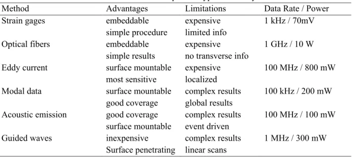
Various NDT techniques have been presented and developed for damage detection in infrastructures over past decades. Most common methods described in Table 2. 1 include: Visual inspection and enhanced visual inspection using liquid penetrant and magnetic particle, eddy current, microwave, thermography, optical interferometry, acoustic inspection, ultrasonic inspection, acoustic emission, and vibration/modal analysis.
Table 2. 1 Available techniques for typical SHM systems.
Method Advantages Limitations Data Rate / Power
Strain gages embeddable
simple procedure expensive limited info 1 kHz / 70mV
Optical fibers embeddable
simple results expensive no transverse info 1 GHz / 10 W Eddy current surface mountable
most sensitive expensive localized 100 MHz / 800 mW
Modal data surface mountable
good coverage complex results global results 100 kHz / 200 mW Acoustic emission good coverage
surface mountable complex results event driven 100 MHz / 100 mW
Guided waves inexpensive
Surface penetrating complex results linear scans 1 MHz / 300 mW
The advantages of SHM over conventional NDT are (Huston, 2010): i. no access to the inspection area required,
ii. safe inspection of hazardous areas,
iii. continuous online monitoring of many locations at the same time, and iv. reduced influence of the human factor on inspection results.
10
Figure 2. 2 Variation of damage delectability versus sensor size for the common SHM techniques in the case of a composite panel of 1 m × 1 m. For each technique, the detection is effective locally (L), on the half plate (H) or on the entire plate (E). The only reliable techniques on the entire structure are GW and modal analysis (Seth Stovack Kessler, 2002).
The relative efficiency of each technique for crack detection on metallic structures is described in Figure 2. 2. On this figure, it appears that the only techniques that are sensitive to cracks on the entire structure are the modal analysis and the GW technique. Since modal analysis give only global results and no local information, GW generation appears to be the most reliable technique for embedded SHM. Smaller sizes of damage reaching a few millimeters can be detected using GWs in the frequency range from 100 kHz to 1 MHz, as seen in Figure 2. 2 for the case of GWs, this gives GW based damage detection techniques advantage over established NDE techniques. The main reason for the limited damage size sensitivity is that the small wavelength waves could interact with the micro-structural details of the material, such as grain size of rolled sheets, thus contaminating the signal with multiple reflections to the degree that it yields no useful information (Seth Stovack Kessler, 2002).
2.3 Damage detection using GWs
Damage could be defined as change(s) to the material and/or geometrical properties of a structure. For instance, loosened bolts, corrosion, and cracks that form in a mechanical part
11
produce a change in geometry that alters the stiffness characteristics of that part could be considered as a damage. Damage could be detected when GWs propagate and interact with it in a structure. This interaction is dependent on type, location, and size of the damage.
2.3.1 GWs propagation in plate-like structures
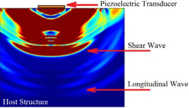
SHM applications tend to monitor large areas of a structure with a minimum number of transducers. Ultrasonic GWs can travel large distances in thin-wall structures, such as pipelines and pressure vessels, with only little loss of energy. GWs are highly sensitive to the interaction with damages, depending on mode and frequency ranges. GWs can be generated by excitation devices, commonly an actuator that is integrated into the structure or bonded on the surface of a structure, to induce normal and shear stress to the host structure. The induced stresses to the plate generate bulk waves known as longitudinal and shear waves, as presented in Figure 2. 3.
Figure 2. 3 Bulk wave generation with a bonded PZT. Longitudinal and shear waves are generated in the plate.
Reflected longitudinal and shear waves superimpose and propagate along a plate-like structure to generate dispersive symmetric (S0, S1, S2, …) and anti-symmetric (A0, A1, A2, …) modes, as shown in Figure 2. 4. Solving the wave equation of motion of the plate, GW symmetric modes are formulated as:
12
( )
( )
(
)
2 2 2 2 tan 4 tan qh k qp ph = − k −q (2.1)and anti-symmetric modes are defined as:
( )
( )
(
)
2 2 2 2 tan tan 4 k q qh ph k qp − = − (2.2) where 2 2 2 2 L w p k c = − , 2 2 2 2 T w p k c= − , k w c= / p. Eq. (2.1), correlates the propagation velocity with its frequency, implying that GWs, regardless of the mode, are dispersive (velocity is dependent on frequency).
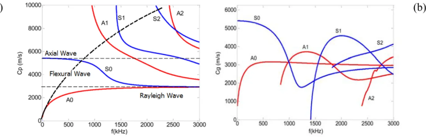
At any given frequency, at least two fundamental (A0 and S0) GW modes are excited simultaneously, and as the frequency-thickness product increases, larger number of modes appear. Figure 2. 5 illustrates the group and phase velocity dispersion curves of a 2 mm thick Al plate for first three symmetric modes, red curves labeled S0, S1, S2, and first three anti-symmetric modes, blue curves labeled A0, A1, A2.
In addition, Figure 2. 5-a shows also phase velocity dispersion curves of Axial, Rayleigh and Flexural waves. At lower frequencies, the velocity of the first symmetric mode (S0) is almost non-dispersive and so close to the speed of axial wave, though A0-mode has very close phase velocity to the flexural wave. However, as the frequency increases, they become separated, and at higher frequency, they differ substantially. At the other end of the spectrum, Rayleigh waves are a high frequency approximation of the S0 and A0-modes. As the frequency becomes very high, the S0 and the A0 wave speeds coalesce, and both have the same value, corresponding to the Rayleigh wave speed. At high frequency, the particle motion of GWs becomes restricted to the proximity of the free surfaces, and thus resembles that of the Rayleigh waves (Giurgiutiu, 2007).
13
Figure 2. 4 Symmetric and anti-symmetric GW modes (Su, Ye, & Lu, 2006).
(a) (b)
Figure 2. 5 (a) Phase velocity dispersion curves for a 2 mm thick aluminum plate. (b) Group velocity dispersion curves for a 2 mm thick aluminum plate (Wan, Zhang, Xu, & Tse, 2014).
2.3.2 GW mode selection
A successful damage inspection with SHM and GWs should be performed based on type of the damage under investigation. Shape, size, geometry, and location of the damage affects its interaction with different GW modes (Alleyne & Cawley, 1992). The selected GW mode should
14
have high sensitivity and detectability to the type of the damage (Wilcox, Lowe, & Cawley, 2001). Furthermore, a proper generated GW mode should be non-dispersive, lightly attenuated and easily excitable (Nicolas Quaegebeur, Micheau, Masson, & Maslouhi, 2011). In addition to proper GW mode selection, frequency of excitation strongly affects damage detection based on the fact that the wavelength of the selected mode must be lower than or equal to the size of the damage (Castaings, Le Clezio, & Hosten, 2002).
Symmetric modes exhibit higher sensitivity to defects anywhere in the thickness such as vertical cracks, loosened bolts (Lemistre & Balageas, 2001). On the other hand, anti-symmetric modes show considerable interaction with surface cracks and corrosion, but it may not be suitable for long-distance propagation because of its high attenuation rate (Pierce, Culshaw, Manson, Worden, & Staszewski, 2000). As anti-symmetric modes have considerable transverse movement, they are very sensitive to defects with horizontal posture such as delamination and transverse ply cracks (Grondel, Delebarre, Assaad, Paget, & Levin, 2001). Thus, this thesis provides a solution for mode-selective GW excitation that improves accuracy of damage detection in SHM systems and decrease, complexity of usage of GWs in these systems since piezoelectric transducers are commonly used in SHM systems to generate GW in plate-like structures, modeling GWs by a PZT considering the coupled piezo-elastodynamic behavior between the actuator and the host medium is one of the fundamental issues for designing a mode-selective actuator.
2.4 Piezoelectric transducers
Waves in elastic structures can be excited using different methods. For NDT purpose the excitation devices that can be used are not necessarily coupled or weakly coupled with the structure, for SHM the wave actuators need to be integrated into the structure or mounted on its surface. A comprehensive review on piezoelectric transducers is performed here for GW excitation. Actually, piezoelectric materials can generate an electric charge an electric charge in response to applied mechanical stress, so called direct piezoelectric effect, as they are used as
15
sensors. On the other hand, the applied electric potential to a piezoelectric materials lead to stress and when they are used as actuators it induces interfacial shear stress to the substructure.
Using coordinate transformation, for linear piezoelectric medium, the stress, strain, electric field, and temperature rise are related by
{ }
{ }
{ }
{ }
t P P e Q Q D Q Q E σ − ε = − , (2.3)where stress
{ }
σ and electrical displacement{ }
D in the plate may be written as{ }
σ = σx σy σxy σyz σxzt,{ }
.t
x y z
D = D D D (2.4)
Also,
{ }
E = Ex Ey Ezt is the electrical field vector; Q , QP , and Qe are the transformed
plane stress reduced stiffness matrix, the matrix of transformed piezoelectric stress module, and the transformed permittivity matrix. The electric field at any point within the plate is expressed as
,
i i
E = −Φ , i =1,2,3. (2.5)
where Φ is the applied potential to the piezoelectric actuator (Yazdanpanah Moghadam, Tahani, & Naserian-Nik, 2013). In this thesis, surface boded PZTs are selected because of their perfect coupling with the host structure. They have a negligible added mass, are easy of integration, excellent mechanical strength, wide frequency responses, low power consumption and acoustic impedance, as well as low cost.
2.4.1 Monolithic piezoelectric transducers
Many investigations have been done to selectively measure and generate GW using PZT. Selecting the desired GW mode depends on the nature of the damage, host-structure, properties and geometries of the type and location of the used transducers, etc. As noted, at any given
16
frequency at least two fundamental GW modes, symmetric mode (S0, S1, S2, …) and anti-symmetric mode (A0, A1, A2, …) can be generated.
(Shelke, Kundu, Amjad, Hahn, & Grill, 2011) used two adjusted and co-localized PZT transducers on the opposite sides of a plate. Therefore, both symmetric and anti-symmetric GW modes could be generated. They investigated the best given frequency and mode type for delamination detection in a laminated plate. A0-mode was selected as the proper mode for delamination detection as its conversion to S0 and A1-modes indicate presence of delamination. It was investigated that A0-mode converts to symmetric mode in interaction as delamination processes, but S0 and S2-modes are not converted to anti-symmetric modes by the delamination. (Santoni et al., 2007) investigated analytically and experimentally the GW-mode tuning with PZT. They found those frequencies in which the amplitude of one of the generated modes completely dominates the other ones. In addition, they tried to find the effective PZT dimension. They concluded that in addition to the given frequency, the shape and geometry of a sensor affect the sensed signal(s).
(Grondel et al., 2001) used dual-element transducers for damage detection in composite plates. They expanded the investigation of (Moulin, Assaad, Delebarre, & Osmont, 2000) about the development of hybrid modeling technique. Based on this method, they tried to select the best GW mode and given frequency for SHM of a composite laminated plate. (Grondel, Paget, Delebarre, Assaad, & Levin, 2002) the found S0 and A0-modes are not significantly dispersive and selected a frequency before appearance of A1-mode to have least dispersion and wavelength. Their investigation concentrated on the A0-mode generation, because of its smaller wavelength than the S0-mode, and its higher detectability consequently. Overall, it is possible to excite a PZT to generate one dominant GW mode. The dimension and geometry of PZT strongly affects mode generation. By selecting the proper frequency, the amplitude of a selected GW-mode can be maximized or minimized. The resonance frequency of the transducer has to be considered in design process to have the required mechanical to electrical conversion (Clarke, Simonetti, & Cawley, 2009).
17
One of the important parameters in optimization of transducers is the material properties. Piezoelectric materials, like polyvinylidene fluoride (PVDF), or piezoceramic (PZT) are commonly used for GW based SHM. Piezopolymers are flexible and can be applied on curved structures. They are lightweight as well as cheaper and easier to manufacture than piezoelectrics (Monkhouse, Wilcox, Lowe, Dalton, & Cawley, 2000). PVDF has higher internal damping than PZT, and they possess a much lower modulus of elasticity and actuation force in comparison to PZT. Thus, piezopolymers are less suitable for actuator applications. Due to the limited temperature range of -40°C to +110°C piezopolymers are inappropriate for aerospace applications. The piezopolymers, with weak piezoelectric properties, high internal losses, low mechanical quality factor and very low acoustic impedance, yield maximum bandwidth when left untuned (Brown, 2000).
2.4.2 Ring and circular piezoelectric transducer
Fundamental symmetric (S0) and antisymmetric (A0) GW-modes are coupled in excitation. If the distance between two edges of a transducer (2a) is equal to the half-integer number of wavelengths (λ) of excited GW-mode as
1
2 ,
2
a=λn+
n = 0, 1, 2, … (2.6)
it can carry maximum energy in low frequency range (Evgeny Glushkov, Glushkova, Kvasha, & Seemann, 2007; EV Glushkov, Glushkova, Seemann, & Kvasha, 2006). Similarly, if the size of the transducer is equal to the integer of a number of the wavelengths, minimal values of energy are obtained.
2a=λn, n = 0, 1, 2, … (2.6)
(Yeum, Sohn, & Ihn, 2011) designed a PZTs to present a mode decomposition technique that is a dual PZT composed of a concentric ring and a circular PZT that can decouple A0 and S0-modes
18
at a given frequency. The approach is based on the changing amplitude rate of S0 and A0-modes, as the sizes of the excitation and sensing PZTs vary. They could define a scaling factor as a function of wavenumbers in which the difference between the wavenumbers of the S0 and A0 -modes rises especially at high frequency. The main investigated parameter here was the inner and outer radius of the ring and circular parts without changing other parameters.
Figure 2. 6 V13 denotes a response measured by the inner circular part of the sensing PZT when both the outer ring and the inner circular parts of the excitation PZT are activated. (Here, the subscripts, 1, 2 and 3 denote the entire dual PZT, the outer ring PZT and the inner circular PZT, respectively.) The darker area of the dual PZT represents the PZT component(s) activated either for excitation or sensing (Yeum et al., 2011).
As shown in Figure 2. 6, ring, circular or entire parts of this transducer can be used to generate and sense the desired mode. For instance, A0-mode can be excited but S0-mode sensed by the sensor, and the difference between A0 and S0 mode is increased at higher frequency, because their formulation is a function of wavenumber and the difference between the wavenumbers of the S0 and A0 modes raised at a high frequency. The advantages of this method over the conventional approaches are that (1) PZTs need to be placed only a single surface of a specimen and (2) mode decomposition can be performed at any desired frequency without changing the PZT size and/or spacing configuration. The proposed method is based on the ‘pin-force’ model (Raghavan & Cesnik, 2005) that considers the interfacial shear stress induces to the host structure mostly around its circumference boundary which is not accurate higher frequencies. In
19
addition, this technique is limited to S0 and A0 modes, therefore, the given frequency was limited below the cutoff frequencies of the S1 or A1 modes.
(EV Glushkov, Glushkova, Kvasha, & Lammering, 2010) investigated a special choice of the amplitudes and time delays of the sinusoidal tone burst driving signals for each element of a PZT with several coaxial ring-shaped elements for mode-selective GW excitation, as shown in Figure 2. 7. As the transient solution tends towards the solution of the corresponding time-harmonic problem for an increasing number of cycles, they defined the driving amplitudes and time delays required via the amplitudes and phase shifts obtained from the related time harmonic problem.
Figure 2. 7 Elastic plate with piezoelectric actuators (EV Glushkov et al., 2010).
2.4.3 Interdigital transducer (IDT)
A popular type of piezoelectric transducers is interdigital transducer (IDT) that are used widely because of their mode selectivity nature, wave directivity, excitation strength, shape flexibility, size and relatively low cost.
20
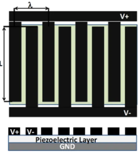
Figure 2. 8 Plane view and cross section of the IDT transducer (Monkhouse et al., 2000).
As shown in Figure 2. 8 , IDT transducer consist of three main layers: bottom (ground) electrode, piezoelectric layer and top (phase) electrodes (Monkhouse, Wilcox, & Cawley, 1997). The second layer, piezoelectric layer, could have different characteristics like the numbers of layers, materials properties, polarization direction, direction of piezoelectric fibers, etc. The material properties of this layer may be of PVDF (Bellan et al., 2005), piezoceramic material (Luginbuhl et al., 1997), piezoceramic composite, or micro fiber composites (MFCs) (Williams, Park, Inman, & Wilkie, 2002).
The most significant part of the IDT is the third layer which consists of top electrode patterns. A number of research efforts are presented in the following in which the pattern of the top electrode was studied. Typically on the top surface, there are two sets of comb shape electrodes. The distance between electrodes (finger separation) defines the length of the induced wavelength λ (Monkhouse et al., 1997), (Monkhouse et al., 2000).
(Mańka, Rosiek, Martowicz, Uhl, & Stępiński, 2010) designed a simple IDT considering wavelength of excited modes. They studied another aspect of IDTs that is directional generation the GWs. GWs are generated in perpendicular direction to the electrodes fingers and divergence of the wave is dependent on the fingers length that is a significant advantage with respect to the
21
standard PZT patch. As will be seen in CLoVER and FSAT sections, it is possible to generate GWs in a specified direction using directional bonded electrodes.
Figure 2. 9 Typical transducer electrode patterns for λ = 2.4 mm (a) plain; (b) apodised (Monkhouse et al., 1997).
They showed that the bandwidth of wave induced by IDT is narrower which can reduce wave dispersion. Moreover, the energy generated by IDT is focused on desired mode. (Hayward et al., 2001) used FEM and experimental methods to study IDTs and plate transducers to generate uni-modal GW. They selected S0-mode for propagation because the S0-mode demonstrates negligible velocity dispersion at lower frequencies. Therefore, the IDT was positioned in the middle of the plate to generate the pure S0-mode, and they could suppress A0-mode.
(Monkhouse et al., 1997) developed a cheap PVDF IDTs for SHM systems in order to strengthen the symmetric modes in plates with different thicknesses and materials. They studied the frequencies at which the selected mode with desired wavelength has the fastest group velocity and least dispersion. As shown in Figure 2. 9, they designed an IDT to excite the A0-mode dominantly by consideration of desired wavelength. By keeping the length of the fingers, they changed the width of the fingers.
22
The materials of electrical connections are important for GW mode excitation. They used copper material connection on their PVDF film. They showed that as the thickness of copper connections increases, the frequency of maximum response is reduced and the low frequency response is improved.
There is a desire to design an IDT with 3600 vision inspection ability. (Monkhouse et al., 2000) expanded their previous work to the IDTs with selective area inspection ability. They designed a 600 sub-transducer with sector IDT, as shown in Figure 2. 10, to generate a uniformly diverging beam. But results showed that the beam covered uniformly around 400 well below the angular aperture (600) of the device and this kind of IDT needs more investigation.
Figure 2. 10 600 radial transducer (Monkhouse et al., 2000).
(Liu, Veidt, & Kitipornchai, 2002) investigated the piezoelectric element interaction effects of array of an IDT for low frequency excitation. They used different parameters in their uncoupled formulation to study the influence of effective parameters on GW generation such as the electrical characteristics of the excitation circuit, the material properties of piezoelectric of the
23
transducer array, the thickness and width of elements, the thickness of the plate and its mechanical properties, the spacing distance between the center of elements, and the number of elements. It was observed that considering the effects of electro-mechanical interaction significantly changes the acoustic wave field generated in all presented cases. This effect was more pronounced for larger number of array elements. They could generate stronger GWs amplitude by increasing the number of the elements in the array, because it increases the transducer’s impedance and the transferred energy form its power source to the elements.
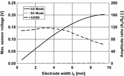
(Schmidt, Sinapius, & Wierach, 2013) designed and optimized the mode selective piezocomposite transducer with applied interdigitated electrodes. As can be seen in Figure 2. 11, to increase the effectiveness of their transducer, they used apodisation, but not for the width of the elements, for the overlaps of each electrode pair that was varying along the transducer designed to excite a specific GW-mode. They studied the width variation of electrodes and amplitude of symmetric and anti-symmetric GW-modes. As can be seen in Figure 2. 12, to maximize one mode and minimize another one, an electrode width of 80% of the half-wavelength seems to be obtained.
Figure 2. 11 Schematic design of an IDT with apodization (Schmidt et al., 2013).
The complexity of analysis of generated GW by piezoelectric composite IDT increases, when using SAW on composite. (Mahapatra, Singhal, & Gopalakrishnan, 2005) used layerwise theory to develop the equivalent single-layer model based on higher order shear deformation (HSDT) and presented a coupled analysis based in spectral element method (SEM), which overcomes
24
some of the modeling difficulties. Using this numerical method, they studied the effect of IDT geometrical parameters, the material properties of the each layer, and finite space-time window. It should be noted that (Mohamed & Masson, 2010) presented two-dimensional SEM as modeling tools specifically tailored for rapid computer aided design of SHM applications because of its advantages in comparison with FEM. (Mohamed, Demers, & Masson, 2011) studied the effect of thickness variation on the fundamental GW S0 and A0 mode using SEM as a solver.
Figure 2. 12 Max. amplitude of A0 and S0 mode at different electrode widths, actuator with 7 electrodes, 40 kHz, 2 mm thick CFRP plate (Schmidt et al., 2013).
2.4.4 Phased array transducer
To overcome disadvantages of traditional transducer array, (J. Li & Rose, 2001) built a multi-channel time-delay system to improve the array technology for GW excitation. As shown in Figure 2. 13, for each of these channels an individual output power control, physical time delay, receiver amplifier, and software time-delay were considered. In fact, the resolution and time domain delays can be determined by sending high energy controllable tone-burst signals from each channel. Based on element spacing and dispersion curves of a thin-wall carbon steel hollow cylinder, they determined time delays.
25
Figure 2. 13 A time-delay system with pulse (physical) delays and software delays for a transducer arrays (J. Li & Rose, 2001).
Figure 2. 14 Illustration of a phased annular array with a time delay dt applied between
each adjacent array elements (Yan, Borigo, Liang, Koduru, & Rose, 2011).
(Yan et al., 2011) used electronically tuning the GW modes and frequencies to apply different loading function in ultrasonic modal analysis technique. Appropriate time delays were applied to a multiple elements annular array transducer to generate A0 and S0-modes selectively, as it is shown in Figure 2. 14. So, they calculated the Hankel transform of the axial source loading profile. They achieved wave mode and frequency tuning by applying proper time delays to each element.
26
2.4.5 Micro-Fiber-Composite (MFC)
MFCs are made of micro piezoelectric fibers that are localized in the matrix construction of a composite that increases directivity of the transducers. The MFC layer can be aligned or sandwiched between two sets of electrode patterns, as shown in Figure 2. 15.
Figure 2. 15 Macro-fiber composite transducer (type P2) with geometrical reference (Matt & di Scalea, 2007).
(Matt & di Scalea, 2007) used Pb(Zr-Ti)O3 (PZT) fibers to study rectangular MFCs or rosettes as sensors. They investigated the effect of angle between fibers and wave propagation directions in MFC sensors and their location. They used four important parameters in their investigation: length, width, thickness and density of arrays of rosettes for covering large areas. Their sensor sensed the propagated A0-mode at higher frequencies where the wavelength is comparable to the sensor’s dimensions due to tuning effects. It was assumed that the wave fields were not affected by the presence of the sensor. The response of the sensor increased as its length increased. Their experimental tests on both composite and sandwich panels showed that the material property of the host structure is an important factor that has to be considered in MFC transducers design.
Piezoelectric fiber composites (PFCs) are used as actuators in some fields, such as vibration control, energy harvesting devices, and SHM (Bent, Hagood, & Rodgers, 1995; Schulz,
27
Sundaresan, Ghoshal, & Pai, 2000; Wilkie, High, & Bockman, 2002). Sensitive factors on GW generation by PFCs are polymeric matrix, fiber volume fraction, fiber orientation and poling direction (Sheng Li & Lissenden, 2010; Lissenden, Li, & Rose, 2010).
Figure 2. 16 Geometry of the finite element model in ABAQUS (S Li & Cliff, 2011).
(Pasco & Masson, 2009) presented an analytical model in order to simulate PFCs with inter-digital electrodes in the plate-like structure in order to allow ultrasonic wave generation at high frequency. They showed that the length of the sensor and wavelength of the desired GW-mode has to be considered in directivity patterns. Like what was seen in (Matt & di Scalea, 2007), they concluded that the angle between the wave propagation and fibers direction affects on sensibility of this sensor. In addition, they fixed PFC actuator and used it for GW generator in particular direction.
(S Li & Cliff, 2011) simulated PFC transducers using ABAQUS software, as shown in Figure 2. 16, to study the sensitivity of this type of transducer for the detection of different kinds of defects. Selected GW-mode can be excited by adjusting fiber spacing to be equal to the wavelength of the desired mode.
2.4.6 Wedge angle transducer
The angle beam method uses wedges to better control mode generation with higher sensitivity (I. Viktorov, 1967). The desired mode can be excited by changing the wedge angle manually or by using a stepper motor. Water immersion or Plexiglas wedges have to be used to couple the
28
ultrasonic angle beam transmission into the host structure. The problem is that the involvement of a mechanical system makes the inspection much longer than an electronic scanning system. (I. Viktorov, 1967) analyzed both theoretically and experimentally the wedge method of generating GWs in isotropic layers. He computed the optimal angle wedge on the neighberhood of the Snell’s law angle of a given wavenumber. Regarding the incidednt beam only insonifies the layer over a finite portion of its surface, he also concluded that there was actually a continuous dependence of the excitation amplitude of any mode on the angle of incidence that is other than being a single angle at which a particular mode could be generated.
(Ditri & Rajana, 1995) developed wedge technique considering the displacement of the excitation amplitude of the desired GW-mode on the angle of incidence of the wedge. They presented the amplitude of the given mode as a function of the Snell’s law phase, and shown its width is dependent only upon the ratio of loading length to wavelength of the mode being generated.
Using two wedge transducers, (Pruell, Kim, Qu, & Jacobs, 2009) presented a technique to identify the plasticity-driven damage by the generated S2-mode. They improved the wedge design and increased the fundamental amplitude five times more that the similar one in (Bermes, Kim, Qu, & Jacobs, 2007), by using a separate screw-tightened piece to apply a constant pressure on the transducer. At one angle, the wedge transducer generates the S1 and S2–mode simultaneously in which their phase velocities are equal. They governed the amplitude of the second harmonic GW by synchronous velocity in which the energy of the fundamental mode transfers to the second harmonic mode. In the measured results, the acoustic nonlinearity increases monotonically with the level of the plasticity. The resonant behavior of the wedge transducer /receiver makes it more sensitive to the S2-mode which is normally weak thus improving the signal-to-noise ratio.
(Rosalie, Vaughan, Bremner, & Chiu, 2004) used both embedded PZT and wedge transducers to detect the delamination in an aluminum plate by considering the group velocity of the GWs.
29
As an application of wedges, (Joo, Park, Lee, Kim, & Lim, 2011) designed and used a wedge transducer for an under-sodium visual inspection of the in-vessel structures. They attached a wedge transducer on a 10 m long ultrasonic waveguide sensor module which consists of a plate waveguide. Then, A0-mode was generated because of its effective radiation capability and its perpendicular displacement to the plate due to the flexural mode and high radiation in the fluid. Because of the contact of the plate and the liquid, the propagated GW become leaky GWs from the solid plate to the longitudinal waves in liquid. They controlled the radiation beam angle ultrasonically by a frequency tuning method of the excitation pulse in the dispersive low frequency range of the A0-mode.
Modes with a small amount of out-of-plane surface displacement have low leakage attenuation and are also hard to excite with an out-of-plane surface force. For this reason alone it would be expected that the angle incidence technique is not a good transduction method to use with low attenuation GW-modes, and this will shortly be demonstrated quantitatively. Alternative transduction schemes must then be investigated. In spite of the capability of the wedge angle transducers for mode-selective GW generation, PZTs are still more attractive to be used in SHM system because the adhesive layer between the PZT and the host structure leads to maximum transmission level of energy to the host structure.
2.4.7 Tilted angle polarization type piezoelectric transducer (TAPP)
Polarization direction can be considered as another parameter in optimization of PZTs transducers. This polarization is usually perpendicular or parallel to the surfaces of the transducer. As shown in Figure 2. 15, (Imano, 2007) used Snell’s law to design a titled angle polarization type piezoelectric transducer (TAPP) with title angle 500 for S
0-mode generation. The TAPP was then manufactured by Fuij Ceramics Co. Ltd.:C-13.