This is an author-deposited version published in :
http://oatao.univ-toulouse.fr/
Eprints ID : 8045
To link to this article : DOI:10.1109/IWECMS.2011.5952367
URL :
http://dx.doi.org/10.1109/IWECMS.2011.5952367
O
pen
A
rchive
T
OULOUSE
A
rchive
O
uverte (
OATAO
)
OATAO is an open access repository that collects the work of Toulouse researchers and
makes it freely available over the web where possible.
To cite this version :
Llibre, Jean-François and Martinez, Nicolas and Nogarede,
Bertrand and Leprince, Pascal
Linear tubular switched reluctance
motor for heart assistance circulatory: Analytical and finite
element modeling
. (2011) In: 10th International Workshop on
Electronics, Control, Measurement and Signals - ECMS-2011, 1-3
jun
e 2011, Liberec, Czech Republic.
Any correspondence concerning this service should be sent to the repository
administrator:
[email protected]
!Linear tubular switched reluctance motor for heart
assistance circulatory
Analytical and finite element modeling
J-F. Llibre, N. Martinez, B. Nogarède
Université de Toulouse; INPT, UPS; ENSEEIHTCNRS; LAPLACE; 2 rue Charles Camichel, BP7122 F-31071, Toulouse Cedex 7, France
P. Leprince
Institut de Cardiologie Groupe Hospitalier Pitié-Salpêtrière47-83 Boulevard de l’hôpital F-75013, Paris, France
Abstract—A linear tubular switched reluctance motor is
presented. This actuator is devoted to be used as a left ventricular assist device (LVAD). In order to avoid thrombosis, this actuator includes pump and valve functions. By using a St. Jude Medical mechanical valve inside the tubular mover, a pulsatile flow is created in the descending aorta. A linear model of a basic pattern of the actuator based on a reluctance network is developed. Then, a two dimensions finite element method analysis is performed in order to check the analytically calculated performances. Relying on these both models, specific requirements for the design of this kind of motor are discussed.
Keywords - switched reluctance motor; finite element; tubular mover; heart assistance
I. INTRODUCTION
Patients suffering from severe heart failure require mechanical circulatory support (MCS). Most of the time, a left ventricular assist device (LVAD) is used. This last one assists the failing left ventricule by providing an additional flow of blood in the body.
At the beginning of heart transplantation, MCSs were pneumatic providing a pulsatile flow. Thus the MCS functioning was close to the heart functioning. The major limitations were the pump bulk, the limited mobility because of a large drive console and the need for chronic anticoagulation [1]. Actually, the last generation of MCS is electromagnetic and provides a continuous flow. For example, the “Debakey VAD”, the “Hearmate II” and the “Jarvik 2000” are miniaturized axial flow pumps (with a turbine and a motor) [2]. The success of these devices is limited by the risk of thrombus in the pump. Moreover, the impact of continuous blood flow on the body remains unknown for the scientific and medical community [3].
We proposed here a new LVAD concept of pulsatile blood pump to be implanted in the aorta descending which is an evolution of that presented in [4]. In order to avoid thrombotic events, this pump called “Pulsamag” incorporates the valve and pump functions. The actuator is a linear switched reluctance motor (LSRM). The stator and the mover have a cylindrical or
tubular shape. A mechanical unidirectional valve is placed inside the mover. The topology of the motor and its main characteristics are described in section II. Section III gives some considerations on the dimensioning and particularly the thrust calculated analytically with the help of a basic pattern of the actuator. A linear model based on a reluctance network of the basic pattern is presented in section IV, while section V is dedicated to the results obtained via a two dimensions finite element method (2D-FEM) analysis. Finally, section VI describes the conclusion and perspectives of the work.
II. PULSATILE PUMP CONCEPT DESCRIPTION
A. Overview of switched reluctance motors
For the application considered, the LSRM is a good candidate. Indeed, its structure is simple and robust. One characteristic is the lack of windings on either the stator or mover part. Usually, the windings are concentrated around the poles rather than distributed. So, the manufacturing and the maintenance are easier and a functioning with a phase shorted or open is possible [5, 6].
There are several types of LSRM. The most frequently studied are counterparts of rotary switched reluctance motors (RSRMs) [5, 6, 7, 8]. The linear configuration can be obtained from the rotating configuration by cutting radially and by unrolling. The windings are concentrated around the poles and the static part is a plate. In [9], a configuration with two E-cores mounted on a carrier structure that moves along a stationary bar is investigated (two air gaps). In [10], a structure called transverse flux tubular switched reluctance motor (TSRM) with concentrated windings around the stator poles is studied (the stator is similar to RSRM one).
An interesting structure is the cylindrical LSRM [11, 12, 13, 14] where the mover part has no windings like [10]. It consists of a moving ferromagnetic cylinder with transverse slots and an outer cylindrical stator containing a number of identical phase sets. Each set consists of a magnetic core, formed of two discs and a ring, and an enclosed solenoidal winding. In the same manner, a six phase cylindrical LSRM has been developed for heart assistance circulatory [15]. A
hybrid form with permanent magnets in the stator was investigated in [16]. The linear pulse motor (LPM) designed consists of a pair of primary stators placed above and below a flat secondary mover (pancake design). A pulsatile total artificial heart (TAH) is then constituted of the LPM, two pusher plates, two sac type blood pumps and four Jellyfish valves [17]. The TAH pumps the blood by expanding and compressing the sacs according to the reciprocating motion of the pusher plates attached to the mover.
B. Presentation of our concept
The objective of the actuator to be implanted in the aorta is to provide a physiological pulsatile flow. It is planned that the actuator ensures both valve and pump functions in a small space. Our LVAD is then composed of a linear actuator (cylindrical LSRM type) equipped with a St. Jude Medical mechanical valve (unidirectional) inside the tubular mover. This 25 mm diameter valve, shown in Fig. 1, allows the blood moving.
Figure 1. St. Jude Medical mechanical valve
The actuator proposed is of the same type as the one studied by [11, 14] and is composed of height stator coils (four phases with two coils per phase) and a tubular mover. The longitudinal cross-sectional view of “Pulsamag” is shown in Fig. 2 and a three dimensional view is shown in Fig. 3.
Figure 2. Basic structure of “Pulsamag”
When the phases are excited sequentially with unipolar current, a magnetic field that slides alternately from one to the other end of the actuator is generated. Then the ferromagnetic cylinder moves back and forth in order to align its saliencies with that of the excited stator phases (maximization of the magnetic flux). During the motion of the cylinder in one direction, the mechanical valve closes and pushes the fluid (blood). In the other direction, the valve opens and thus limits its influence on the fluid.
Figure 3. Three dimensional view of “Pulsamag”
In this low speed application, because of low eddy current losses, the magnetic core does not have to be made of laminated steel. Moreover, due to the cylindrical shape, the normal forces are neutralized. The other advantages of this type of actuator are its reliability, its simplicity of implementation, its ability to generate a linear motion directly (without mechanical processing)...
One of the main drawbacks is the difficulty of guiding the mover part in order to ensure a constant air gap. The latter is usually small to ensure good performances.
C. Desired mechanical characteristics
The physiological requirements for a LVAD are a flow of 3 liters per minute (l/min) and a pressure of 120 mmHg (16 kPa) under a 2 Hz frequency (120 beats per minute). The thrust F (in N) and the stroke L (in mm) of the mover are given by: 10 . . 6 103 S P F f S Q L= = . (1)
Where Q is the flow (l/min), S is the cross-section (cm²), f is the frequency (Hz) and P is the pressure (kPa).
Thus, with a 25 mm diameter valve, the stroke and the required thrust could reach 51 mm and 8 N respectively. In the next section, we present an analytical model based on a basic pattern in order to give elements on the dimensioning of the actuator.
III. ANALYTICAL MODEL OF THE ACTUATOR
A. Basic pattern
We can see in Fig. 2 that each phase set of the actuator forms an independent magnetic circuit thanks to the nonmagnetic ring. So we can consider one set and extrapolate the results to the entire actuator.
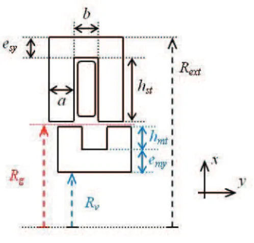
The basic pattern of the actuator is then constituted of a stator ferromagnetic part with one slot (with a coil) and two teeth and a mover ferromagnetic part with one slot (without coil) and two teeth as we can see in Fig. 4. To build the whole actuator, the modules are stacked, separated by a stator nonmagnetic ring.
Figure 4. Basic pattern
The notations of the axial and radial geometrical dimensions, presented in Fig. 4 are: a tooth width, b slot width,
Rv valve radius, Rg air gap radius, Rext external radius, hmt mover tooth length, emy mover yoke thickness, hst stator tooth length and esy stator yoke thickness.
In order to ensure a smooth and regular functioning, we have chosen the tooth pitch of the stator λs and the tooth pitch of the mover λm equal:
b a m
s =λ =λ= +
λ . (2)
The tooth width a and the slot width b of the stator and the
mover are chosen equal too:
b
a = . (3)
B. Analytical static force calculation
When operating in linear mode, the magnetic energy Wmag and the magnetic co-energy Wc are equal and can be expressed by:
( )
( )
( )( )
2 . 2 1 , ,y W i y y Ni i Wmag = c = P . (4)Where N is the number of coil turns, i is the current supply,
y is the position of the mover and P is the permeance. The
force Fy along axis y is done by:
( )
( ) ( )
cte Ni cte Ni c y Ni y y y y i W F = = ∂ ∂ = ∂ ∂ = 2 . 2 1 , P . (5) Assuming that the magnetic material does not saturate and that the magnetic relative permeability is infinite, the permeance P in (5) is limited to the air gap permeance Pg.For a step ∆y, as we can see in Fig. 5, the variation of the air gap permeance ∆Pg is done by:
( )
(
)
g y R g S y g g g 2 2 2 0 0 µ ⋅ π ⋅∆ = ⋅ µ = ∆P , (6)where g is the air gap length and Sg is the average cross section of the flux tube.
Figure 5. Calculation of air gap permeance
Finally, the mean static force for a basic pattern Fy is done by:
( )
2 0 2g Ni R Fy g ⋅ π µ = . (7)This expression is identical to that given by [14].
The magnetomotive force Ni can be calculated in terms of the air gap induction Bg as:
0 2
µ = g Bg
Ni . (8)
Than the force Fy in terms of the air gap induction Bg is:
2 0 2 g g y gR B F ⋅ µ π = . (9)
The same expression of the force can be found in [5, 10]:
XZ B Fy g ⋅ µ = 0 2 2 , (10)
where X and Z are respectively equal to 2g and 2πRg (the product XZ is the air gap exchange area).
C. Elements for dimensionning
According to (7), we can notice that the mean thrust is high if the air gap length g is small and the radius air gap Rg is high. In our structure, Rg is greater than the valve radius Rv but cannot be too high because of the limited volume of the actuator (implantation in the human body).
We can also notice that the thrust is proportional to the square of the magnetomotive force. Thus the increasing of the current leads to an increasing of the thrust but also an increasing of the copper loss (square increasing). One dimensioning factor for switched reluctance motors is the maximization of the mean torque per copper loss. In [14], this optimization gives the following result:
(
)
(
ext sy)
g R e
R ≅ 2−1⋅ − . (11)
If we neglect in (11) the stator yoke thickness esy compared to the external radius Rext, the optimum ratio is 0.4 between the
air gap radius Rg and the external radius Rext. Then the stator tooth length hst is equal to 1.4 times Rg.
The stroke of the actuator is another major consideration for the dimensioning. To increase the stroke, we can increase the basic pattern number i.e. the phase number m and/or the coil per phase number n. By supplying several coil in serial (n ! 1), both the stroke and the thrust increase.
We can notice in Fig. 2 that to separate two basic patterns, a nonmagnetic ring thickness of c value has to be inserted. The mechanical step yp of the actuator is done by:
c b m p = − λ = λ . (12)
For example, when the phase number one is excited, a force is produced between the stator and the mover in order to maximize the magnetic flux (stator and mover teeth in aligned position). Then the distance between the stator tooth of the next phase (phase number two for example) and the closest mover tooth is λp.
D. Dimensions of the prototype
The actuator presented in Fig. 2 has got m = 4 phases and
n = 2 coils per phase. Moreover, the tooth and slot widths are
equal as written in (3). From (12), we can deduce that:
c a p = = λ = λ 2 4 . (13)
The supplying of the coils 1-5 (phase 1), 2-6 (phase 2), 3-7 (phase 3) and 4-8 (phase 4) by a four-phase current system leads to a leftward shift whereas the reverse sequence 1-5, 4-8, 3-7 and 2-6 leads to a rightward shift.
The external radius Rext according to (11) will be larger than 31 mm considering the radius valve value Rv which is equal to 12.5 mm. In order to limit the bulk of the actuator (external radius inferior to 30 mm) and the mass of the mover, we have chosen the dimensions given in Table I.
TABLE I. PROTOTYPE DIMENSIONS
Name Abbreviation Size (mm)
Valve radius Rv 12.5
Mover yoke thickness emy 2
Mover tooth length hmt 1.5
Air gap g 0.2 Air gap radius Rg 16.1
Stator tooth length hst 9
Stator yoke thickness esy 1.5
External radius Rext 26.7
Tooth width a 2.9 Slot width b 2.9 Nonmagnetic ring thickness c 1.45
The total length of the stator LsT is given by:
(
a b) (
m n)
c nm
LsT = ⋅ ⋅ 2 + + ⋅ −1 ⋅ . (14) The total length of the mover LmT is dependant of the desired stroke:
sT mT stroke L
L ≥ + . (15)
With the previous dimensions done, the external length dimensions of the prototype are: LsT ≅ 80 mm and LmT " 130 mm.
The total expected thrust FyT is given by:
( )
2 0 2g Ni R n FyT g ⋅ π µ ⋅ = . (16)To reach the desired thrust of 8 N, the magnetomotive force
Ni is equal to 158 At (considering a slot fill factor of 100 %
and n = 2 coils per phase).
IV. LINEAR MODEL BASED ON RELUCTANCE NETWORK
A. Reluctance network
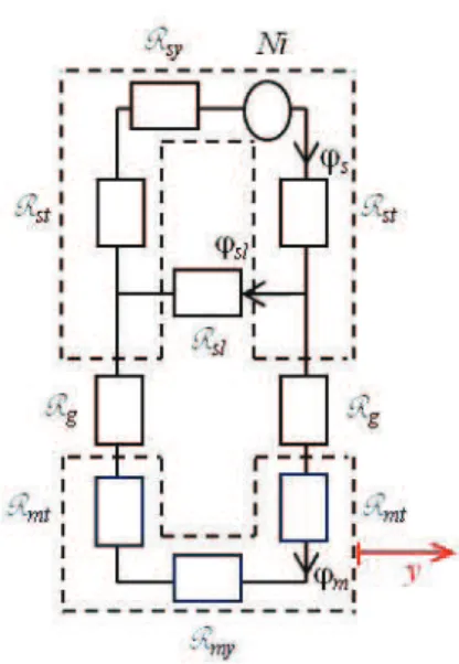
The basic pattern of Fig. 4 can be modeling by using the reluctance network of Fig. 6 [14]. We consider that the magnetic material is linear with a constant permeability µ.
Figure 6. Reluctance network of the basic pattern
The stator flux ϕs is divided in one slot leakage flux ϕsl and one useful flux ϕm reaching the mover.
The air gap reluctance Rg varies with the position y of the
mover. An axial magnetic flux flows through the stator tooth reluctance Rst, the mover tooth reluctance Rmt and the air gap
reluctance Rg. A radial magnetic flux flows through the stator
yoke reluctance Rsy and the mover yoke reluctance Rmy. The
slot leakage flux ϕsl is modeled by the specific reluctance Rsl. The reluctances are listed in Table II.
TABLE II. RELUCTANCE VALUES Name Expression air gap reluctance R y g g g ∆ π ⋅ µ = 2 0 R stator tooth reluctance
[
(
R e) (
R g)
]
a h g sy ext st st ⋅ + + − π ⋅ µ = 5 . 0 R mover tooth reluctance[
(
R g) (
R g h)
]
a h mt g g mt mt ⋅ − − + − π ⋅ µ = 5 . 0 5 . 0 R stator yoke reluctance[
2(
)
2]
2 sy ext ext sy e R R b a − − π ⋅ µ + = R mover yoke reluctance[
(
) (
2)
2]
5 . 0 5 . 0 2 my g g my e g R g R b a − − − − π ⋅ µ + = R slot leakage reluctance h(
h(
R g)
)
b g st st sl 5 . 0 4 3 6 0⋅π + + µ = R B. Force calculationWith the help of Matlab software we have calculated the reluctances and the fluxes above mentioned for several magnetomotive forces in function of the displacement ∆y of the mover. The relative permeability of the magnetic material was taken constant and equal to 1000.
The static force Fy for a specific value of magnetomotive force NI is done by:
( )
( )
(
)
1 1 2 1 − − − ϕ − ϕ = ∆ ∆ = k k k k NI c NI y y y y y NI y y W F . (17)We consider in this section that the entire slot is filled with copper (slot fill factor of 100 %) i.e.:
J bh
NI = st ⋅ . (18)
So for a current density J of 10 A/mm² in the slot, the magnetomotive force NI is equal to 261 At (26.1 mm² slot area).
By using (17), we can then calculate the force for different positions of the mover for a given magnetomotive force value. Fig. 7 shows the static force versus the relative displacement called “shift” (expressed in %) for different magnetomotive forces (the corresponding density current in the slot is between 2 A/mm² to 10 A/mm² with a step of 2 A/mm²). When the stator and the mover teeth are in aligned position (maximum flux), the shift is 0%. For a displacement equal to the mechanical step yp, the shift is 50%.
We can notice that for a magnetomotive force of 261 At and a shift of 50 % (corresponding to the maximum thrust in the actuator), the force is near 10 N.
We can compare this result to 10.8 N which is the value obtained by using (7).
Figure 7. Force versus shift
V. TWO DIMENSION FINITE ELEMENT METHOD ANALYSIS
A. Flux density and force determination
The basic pattern of Fig. 4 has been simulated with the help of Ansys software by using the same magnetic characteristics than the previous model. We can see in Fig. 8 the flux lines and the magnetic flux density for a shift equal to 25 % and a current density in the slot equal to 10 A/mm².
Figure 8. Flux line and magnetic flux density plots for J = 10 A/mm² and shift = 25%
We can see that the magnetic flux density in the air gap is around 0.8 T and the induction in the yoke is around 1 T. There are some local areas where the magnetic flux density is high.
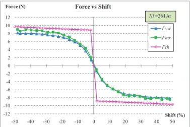
Fig. 9 shows the static electromagnetic force computed using two techniques: the Maxwell stress tensor “Fmx” and the
Rv
virtual work principle “Fvw”. We have also plotted the analytical force “Fth” calculated previously in Fig. 7.
Figure 9. Force versus shift for J = 10 A/mm² (i.e. NI = 261 At)
We can notice that the forces are similar, which validates the previous model.
B. Prototype dimensioning
The prototype build is shown in Fig. 10. The active stator length is 80 mm and the mover length is 140 mm (30 mm stroke on each side) according to (14) and (15).
Figure 10. Pulsamag prototype
The slot fill factor is equal to 52 % and the number of turns
N in a coil is equal to 155. With a supply current I equal to 1 A,
the magnetomotive force is equal to 155 At and the current density in the coil is equal to 11.4 A/mm².
For one basic pattern, as we can see in Fig. 7, the expected thrust will be close to 3.5 N. Because there are two coils per phase excited, the expected thrust will be equal to 7 N. In order to reach the desired thrust mentioned in II.C, it will be necessary to supply two phases at the same time or to double the current during a part of the electrical period.
VI. CONCLUSION
We have presented in this paper a linear tubular switched reluctance motor for mechanical circulatory support. A
mechanical valve is inserted inside the mover in order to create a pulsatile flow. A theoretical study and a FEM Analysis were performed on a basic pattern using linear magnetic materials. These studies suggest that the actuator can provide the stroke and the thrust necessary for the intended application. In order to validate this concept, we plan to make experimental tests for different electrical power supply strategies.
REFERENCES
[1] P.L. DiGiorgi, Y. Naka, M.C. Oz, “Left ventricular assist devices,” Contemporary Cardiology: Surgical management of congestive heart failure, Chapter 7, 2005, pp. 155–189.
[2] A. Blitz, J.C. Fang, “Ventricular assist devices and total artificial hearts,” Contemporary Cardiology: Device Therapy in Heart Failure, Chapter 13, 2009, pp. 339–371.
[3] G.S. Allen, K.D. Murray, D.B. Olsen, “The importance of pulsatile and non pulsatile flow in the design of blood pumps,” Artificial Organs, vol. 21, issue 8, 1997, pp. 922–928.
[4] N. Martinez, P. Leprince, B. Nogarede, “A novel concept of pulsatile magnetoactive pump for medical circulatory support,” 18th International
Conference on Electrical Machines, ICEM, 2008, pp. 1–6.
[5] B-S. Lee, H-K. Bae, P. Vijayraghavan, R. Krishnan, “Design of a linear switched reluctance machine,” IEEE Trans. Ind. Appl., Vol. 36, No. 6, 2000, pp. 1571–1580.
[6] M.R.A. Calado, A. Espirito Santo, S.J.P.S. Mariano, C.M.P. Cabrita, “Characterization of a new linear switched reluctance actator,” International Conference on Power Engineering Energy and Electrical Drives, POWERENG'09, 2009, pp. 315–320.
[7] D.S.B. Fonseca, C.P. Cabrita, M.R.A. Calado, “Linear switched reluctance motor. A new design methodology based on performance evaluation,” International Conference on Industrial Technology, IEEE ICIT'04, Vol. 1, 2004, pp. 519–524.
[8] D.S.B. Fonseca, T.J.B. Godinho, C.P. Cabrita, “Electromagnetic characterization of a linear reluctance actuator. A new approach,” 18th
International Conference on Electrical Machines, ICEM, 2008, pp. 1–6. [9] D.G. Taylor, R. Ahmed, “Current limited optimal excitation of
magnetically coupled linear variable reluctance motors,” IEEE International Electric Machines and Drives Conference, IEMDC'03, Vol. 2, 2003, pp. 857–860.
[10] I-A. Viorel, K. Hameyer, L. Strete, “Transverse flux tubular switched reluctance motor,” 11th International Conference on Optimization of
Electrical and Electronic Equipment, OPTIM'08, 2008, pp. 131–136. [11] J. Corda, E. Skopljak, “Linear switched reluctance actuator,” 6th
International Conference on Electrical Machines and Drives, 1993, pp. 535–539.
[12] J. Corda, M. Wilkinson, “Modelling of static thrust characteristics of cylindrical linear switched reluctance actuator,” 7th International
Conference on Electrical Machines and Drives, 1995, pp. 354–358. [13] J. Corda, B. Ouhab, “Electromagnetic design optimisation of a
linear-cylindrical variable-reluctance motor,” 9th International Conference on
Electrical Machines and Drives, 1999, pp. 276–280.
[14] L. El Amraoui, F. Gillon, S. Vivier, P. Brochet, M. Benrejeb, “Optimal design approach for linear tubular machines,” IEEE International Conference on Systems Man and Cybernetics, Vol. 5, 2002, pp. 1–6. [15] H. Yamada, T. Hamajima, S. Xiang, N. Nishizawa, “Six-phase linear
pulse motor as linear oscillatory actuator,” IEEE Trans. On Magn., Vol. MAG-23, No. 5, 1987, pp. 2841–2843.
[16] M. Karita, Y. Sato, H. Yamada, “Mock circulatory test of linear pulse motor-driven artificial heart,” IEEE Translation Journal on Magnetics in Japan, Vol. 6, Issue 7, 1991, pp. 560–568.
[17] H. Yamada, T. Mizuno, H. Wakiwaka, Y. Izumi, Y. Kataoka, M. Karita, M. Maeda, Y. Kikuchi, “Drive control of linear pulse motor for artificial heart,” International Conference on Power Electronic Drives and Energy Systems for Industrial Growth, Vol. 1, 1998, pp. 427–431.
-12 -10 -8 -6 -4 -2 0 2 4 6 8 10 12 -50 -40 -30 -20 -10 0 10 20 30 40 50 Force (N) Shift (%) Force vs Shift Fvw Fmx Fth NI =261At

![TABLE II. R ELUCTANCE VALUES Name Expression air gap reluctance R yg gg=µ⋅π ∆02R stator tooth reluctance [ ( R e ) ( R g ) ] ah gsyextstst=µ⋅π−+ + ⋅5.0R mover tooth reluctance [ ( R g ) ( R g h ) ] ahmtggmtmt=µ⋅π−+−−⋅5.05.0R stator yoke](https://thumb-eu.123doks.com/thumbv2/123doknet/3664233.108359/6.892.476.815.83.410/eluctance-values-expression-reluctance-reluctance-gsyextstst-reluctance-ahmtggmtmt.webp)