Use of second generation coated conductors for efficient shielding of dc
magnetic fields
J. F. Fagnard,1,a兲M. Dirickx,1G. A. Levin,2P. N. Barnes,2B. Vanderheyden,3and P. Vanderbemden3
1
SUPRATECS, CISS Department, Royal Military Academy, B-1000 Brussels, Belgium
2Propulsion Directorate, Air Force Research Laboratory, Wright-Patterson AFB, Ohio 45433, USA 3SUPRATECS, Department of Electrical Engineering and Computer Science, University of Liège, B-4000 Liège, Belgium
共Received 27 April 2010; accepted 4 June 2010; published online 15 July 2010兲
This paper reports the results of an experimental investigation of the performance of two types of magnetic screens assembled from YBa2Cu3O7−␦ 共YBCO兲 coated conductors. Since effective screening of the axial dc magnetic field requires the unimpeded flow of an azimuthal persistent current, we demonstrate a configuration of a screening shell made out of standard YBCO coated conductor capable to accomplish that. The screen allows the persistent current to flow in the predominantly azimuthal direction at a temperature of 77 K. The persistent screen, incorporating a single layer of superconducting film, can attenuate an external magnetic field of up to 5 mT by more than an order of magnitude. For comparison purposes, another type of screen which incorporates low critical temperature quasipersistent joints was also built. The shielding technique we describe here appears to be especially promising for the realization of large scale high-Tcsuperconducting screens. © 2010 American Institute of Physics.关doi:10.1063/1.3459895兴
I. INTRODUCTION
Magnetic screening is of technological importance for a variety of applications requiring an ultralow magnetic field environment, including biomedical,1naval,2or fundamental research instrumentation like superconducting quantum in-terference devices3 or cryogenic current comparators 共CCCs兲4
necessitating field attenuation larger than 106.5 The traditional approach to shielding low-frequency magnetic fields is to use high permeability ferromagnetic materials such as permalloy or mu-metal.6At cryogenic temperatures 共77 K and below兲, high temperature superconductors 共HTSs兲 often exhibit better low-frequency shielding performances than those of ferromagnets as follows: e.g., magnetic field attenuations in excess of 105 can be attained with Bi-2223 ceramics at 77 K.6 With such an attenuation level, HTS are good candidates5,7for replacing classical CCC based on low temperature superconductors.4
Until recently, HTS shields have been made out of bulk materials.5,8–10The significant progress in manufacturing the second generation 共2G兲 coated conductors11,12 has opened a possibility that they can be used as a material for magnetic screens. A recent study13 reported the use of YBCO coated conductors to attenuate ac magnetic fields at low frequencies 共10–100 Hz兲. A distinction should be made between “ac” and “dc” shielding. In the ac regime, the flux density B共t兲 = B0sin共t兲 at the sample surface induces alternating
shield-ing currents that are limited by both the equivalent resistance
R and self-inductance L of the current loop. The magnetic
field can be attenuated if the resistance R is finite provided the condition RⰆL is met. In the dc regime, however, an
effective superconducting shield requires the existence of
persistent current loops. In this paper, we show that loops
made of 2G tapes can be candidates for replacing HTS bulks as efficient cylindrical dc magnetic shields.
II. EXPERIMENT
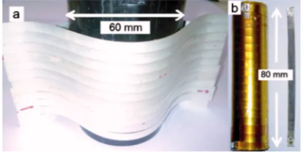
The screening shell was assembled from eleven 12 ⫻150 mm2 sections of coated conductor manufactured by SuperPower.14 The average critical current共Ic兲 of these sec-tions at 77 K is⬃170 A. Similar to Ref.15, along the center line of each 150 mm long section a 1 mm wide, 124 mm long slit was milled leaving a superconducting film in the form of a closed race track. Extended over a cylinder, such a section forms a superconducting closed loop. The magnetic shield, called Screen A, is assembled by stacking 11 sections, one on top of another, over a 60 mm diameter nonmetallic holder to form a quasicylindrical shell. Screen A has an “eye-shaped” cross-section as shown in Fig. 1共a兲. A preliminary
a兲Electronic mail: fagnard@montefiore.ulg.ac.be.
FIG. 1. 共Color online兲 共a兲 Screen A—a screening shell assembled from 11 sections of 2G tape stacked together around a 60 mm diameter cylinder.共b兲 Screen B is an 18 turn solenoid which can be either open or short-circuited by a 80 mm long superconducting tape.
JOURNAL OF APPLIED PHYSICS 108, 013910共2010兲
0021-8979/2010/108共1兲/013910/4/$30.00 108, 013910-1 © 2010 American Institute of Physics
characterization of the magnetic properties of each individual loop is carried out in order to place the best samples system-atically in the central zone of the stack.
The properties of Screen A were compared with those of a more conventional solenoidal coil. Screen B is made out of a similar 2G YBCO 4 mm wide tape from American Super-conductor 共Ic⬃70 A at 77 K in self-field兲.14 The length of the solenoid is 80 mm关Fig.1共b兲兴. Its diameter 共20 mm兲 was made intentionally smaller than that of Screen A. This allows us to insert Screen B into the sample chamber of a physical property measurement system 共Quantum Design兲 and to carry out measurements at temperatures down to 2 K. The ends of the solenoid can be either left open共“open” configu-ration兲 or connected by soldering an 80 mm long 2G tape 共“closed” configuration兲. The superconducting critical tem-perature of indium used as a solder is 3.4 K.
The attenuation by a screen was determined as follows: the screen was zero-field cooled, then an axial magnetic field
Bapp was applied and the magnetic flux density inside the shield, Bin, was measured using a high sensitivity Hall probe.9The shielding factor共SF兲 is defined as SF=Bapp/Bin. The external field Bappwas ramped up from zero to the maxi-mum value at a constant rate. The dc properties reported below correspond to a very low sweep rate 共10 to 800 T/s兲.
III. RESULTS AND DISCUSSION A. Conventional solenoidal coil
First we examine the dc SF of a conventional solenoidal coil 共Screen B兲 under a 12 T/s sweep rate. At T=77 K 共not shown兲, no shielding is observed in either configuration. Figure2shows SF between 2.5 and 4 K. The inset shows the corresponding Binversus Bappdata. In the open configuration,
Binequals the applied magnetic field at all temperatures. In the closed configuration, a magnetic shielding共i.e., SF⬎1兲 is clearly observed at 2.5 and 3 K. This is attributed to the superconducting transition of indium at 3.4 K. As a result, the contact resistance strongly decreases allowing much greater azimuthal screening current to flow through the
sole-noid. Note that the critical field of indium is 15 mT at 2.5 K and 7 mT at 3 K.16These values, indicated by arrows in Fig. 2, are consistent with the field amplitudes at which the shield effect disappears.
In coated conductors the interfacial resistance reported in the literature is of the order of 50 n⍀ cm2.17–20
In Screen B the contact area is 4⫻4 mm2 so that a joint resistance ⬃100–300 n⍀ seems to be a reasonable estimate. A sole-noid like Screen B 共self-inductance L⬃1 H兲, “short-circuited” by a superconducting tape with two 100 n⍀ joints, has a time constant ⬃5 s. For a given sweep rate dBapp/dt, the resistance of the joints will render magnetic shielding ineffective above a threshold induction Blim ⬃共dBapp/dt兲, i.e., ⬃0.06 mT for a sweep rate of 12 T/s. Thus, the results of Fig. 2 provide direct experimental evi-dence that under small sweep rates 共dc operation兲 an effec-tive shield made of 2G superconductors requires a macro-scopic persistent current.
B. Shield assembled with slit coated conductors
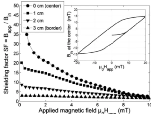
Let us now consider the effectiveness of the screening shell assembled from the slit conductors 关Screen A, Fig. 1共a兲兴. Figure 3 shows the SF measured in the center of the coil 共circles兲 at a 720 T/s sweep rate; the inset shows a complete hysteresis curve with the external field Bappramped up to 20 mT and cycled subsequently between two symmet-ric values. As the applied magnetic field increases, Bin is smaller than Bappdue to the shielding currents flowing along the tape loops. This leads to a SF greater than 10 for applied fields up to 5 mT. The relatively low value of the SF is mainly due to a small aspect ratio l/D⬃1, where l is the
length and D the diameter of the Screen A.6
In order to estimate the influence of the finite size of the Screen A on its effectiveness, it is of interest to compare our measured SF to the theoretical results expected for an ideal screen made of type-I superconductor of the same dimen-sions. Grohmann and Hechtfischer21have shown that the in-ternal magnetic field along the axis of a cylindrical semi-infinite type-I superconducting screen, close to the open ends, follows an exponential decaying function of the dis-tance from the open end. Magnetic measurements and mod-FIG. 2. SF measured in the center of Screen B at 4, 3, and 2.5 K. The open
and solid symbols refer to the solenoid either in open or closed configura-tion, respectively. Inset: the dependence of Binvs applied field.
FIG. 3. SF measured on the axis of Screen A at several elevations from the center. Inset: hysteresis loop measured at the center of Screen A.
013910-2 Fagnard et al. J. Appl. Phys. 108, 013910共2010兲
eling have shown that this exponential law holds true for HTS tubes subjected to small magnetic fields.6A useful ap-proximation of the SF in the vicinity of the opening end is given by
SF⬃ exp
冉
2Cl/2 − zD
冊
, 共1兲where z is the elevation from the center of the cylinder and
C⬇3.83 is the first zero of the Bessel function of the first
kind, J1共x兲. At the center of an ideal type-I superconducting tube, with roughly the same dimensions as those of Screen A 共l=5.5 cm and D=6 cm兲, the SF is ⬃33.5, a value which is close to the experimental values measured on Screen A at the lowest fields 共circles in Fig. 3兲, e.g., SF=35 at Bapp = 0.5 mT. The agreement between our experimental results and the theoretical estimate for an ideal type-I screen thus confirms that the limitation of the SF measured on Screen A is caused by the relatively small aspect ratio l/D⬃1. For comparison, at the center of an ideal type-I superconducting tube, with roughly the same dimensions as those of Screen B 共l/D=4兲, the theoretical SF would be 4.5⫻106, which is five orders of magnitude higher than for a shield whose aspect ratio equals 1.
The small value of the aspect ratio also has an impact on the threshold induction, Blim, above which the shielding is ineffective. In the framework of the critical state model, the threshold induction Blim equals the full penetration field. Therefore, the correcting factor, 共CF兲, of the threshold field for a type-II cylinder of finite length with respect to that of an infinite cylinder can be estimated from the CF for the full penetration field; the analytical expression reads:22
CF = l 2Dln
再
2D l +冋
1 +冉
2D l冊
2册
1/2冎
. 共2兲If the eye-shaped cross-section is not taken into account, the correction for Screen A can be estimated to be⬃0.7.
The inset of Fig.3shows the penetration of the magnetic field after the threshold value, Blim. Above Blim, the magnetic flux density inside the shield scales linearly with Bapp. When the direction of Bapp is reversed, the internal magnetic flux density follows a hysteresis curve, yielding a remnant induc-tion of 6.4 mT. The corresponding current circulating in each loop, by taking into account the cross-sectional shape and the finite length of the coil is estimated to be 42.5 A, which is smaller than the expected critical current of the slit tape. The reason is that the electromotive force共S⫻dBapp/dt, where S denotes the “eye” cross-section of a loop兲 gives rise to a smaller electric field E than the usual threshold value Ec = 1 V/cm used for the determination of Ic. A smaller cur-rent density is then expected because of the rather low
n-values of E = Ec共I/Ic兲n observed in coils made of 2G conductors.23
Finally, SF was also measured at several points along the
z-axis. The results are qualitatively in agreement with Eq.
共1兲. The measurements共Fig.3兲 show that the shielding effect even manifests itself close to the top/bottom of the shell 共z = 3 cm兲, where SF values exceeding 3 are observed up to
Bapp= 2 mT.
The measurements reported above demonstrate the po-tential of the screening shell assembled from the slit conduc-tors for screening axial magnetic fields. It is of interest to comment on the ability of such shields for screening mag-netic fields of any direction, and in particular transverse magnetic fields. The superconducting shielding of a trans-verse magnetic field is, in general, less efficient than the axial shielding because of demagnetizing effects. In the case of type-I superconductors subjected to a transverse magnetic field, it has been shown theoretically and experimentally that an exponential decay of the magnetic field occurs from the extremity of the cylinder similarly as in the axial configuration.21This decay is described by the same equation in both configurations关Eq.共1兲兴, where now C⬇1.84 is lower than in the axial configuration. Similarly, our previous work on bulk HTS cylinders9has shown that both demagnetizing effects and a small finite aspect ratio lead to a Blim that is smaller in the transverse configuration than in the axial con-figuration. Another limitation arises from the fact that shield-ing currents can only flow in discrete areas limited by the width of the different tapes making the structure of the shield and not on the whole lateral surface of the shield. For these reasons, the stacked structure of Screen A is expected to provide shielding efficiency against a transverse magnetic field that is smaller than in the axial configuration. In order to increase the shielding efficiency in transverse configura-tion, the width of the tapes and the height of the screen should be as large as possible and a multilayer structure with overlaps should be preferred in order to reduce flux leakage between adjacent tapes.
IV. CONCLUSION
In summary, the measurements reported above demon-strate a possibility to assemble a magnetic screen using state-of-the-art YBCO coated conductors. An effective screening of a low sweep rate 共dc兲 magnetic field is possible at tem-peratures as high as 77 K. The described method allows as-sembling a superconducting screen of practically unlimited volume with consistent properties using coated conductors instead of bulk superconductors. The circulating persistent current共and the screening factor兲 can be scaled up by stack-ing several slit coated conductors on top of each other before expanding such a loop over the coil former.15The neighbor-ing sections of the screen can be made to overlap, preventneighbor-ing magnetic field leakage through the “magnetic cracks” be-tween the adjacent tapes.
A potential large-scale application that can benefit from persistent magnetic shields made out of coated conductors is inductive fault current limiters 共FCLs兲.24,25 These devices function similar to a transformer with superconducting short-circuited secondary winding. The superconducting winding 共typically a cylinder兲 serves as a perfect magnetic shielding for the primary winding. This results in low residual imped-ance during normal operation. When the current in the pri-mary winding exceeds a certain limit, the induced current in the superconducting shield also exceeds the critical current, leading to increased impedance.
For the inductive FCL, it seems likely that a large size
013910-3 Fagnard et al. J. Appl. Phys. 108, 013910共2010兲
superconducting shield assembled from coated conductors somewhat similar to the arrangement shown in Fig. 1 here and that in Ref.15will have advantage over a bulk YBCO in several respects—the consistency of the superconducting properties, potentially lower ac losses, as well as the lower cost and complexity of the manufacturing processes. More work on persistent magnetic shields made out of coated con-ductors is needed to clarify the scope of the problems to be solved and the scale of the potential advantages that may be associated with such shields.
1H. Ohta, M. Aono, T. Matsui, Y. Uchikawa, K. Kobayashi, K. Tanabe, S.
Takeuchi, K. Narasaki, S. Tsunematso, Y. Koyabu, Y. Kamekawa, K. Na-kayama, T. Shimizu, K. Koike, H. Hoshino, E. Kotaka, H. Sudoh, Y. Takahara, K. Yoshida, M. Shinada, Y. Takahata, Y. Yamanda, and K. Ka-mijo,IEEE Trans. Appl. Supercond.9, 4073共1999兲.
2J. J. Holmes, Synthesis Lectures on Computational Electromagnetics
共Morgan and Claypool, Arizona State University, 2008兲, Vol. 3.
3K. Kamiya, B. Warner, and M. DiPirro,Cryogenics41, 401共2001兲. 4K. Grohmann, H. D. Hahlbohm, H. Lübbig, and H. Ramin,Cryogenics14,
499共1974兲.
5T. Watanabe, S. Watanabe, T. Ikeda, M. Kase, Y. Sasaki, T. Kawaguchi,
and T. Katayama,Supercond. Sci. Technol.17, S450共2004兲.
6S. Denis, L. Dusoulier, M. Dirickx, P. Vanderbemden, R. Cloots, M.
Aus-loos, and B. Vanderheyden,Supercond. Sci. Technol.20, 192共2007兲. 7G. Giunchi, E. Bassani, T. Cavallin, N. Bancone, and F. Pavese,
Super-cond. Sci. Technol.20, L39共2007兲.
8J.-F. Fagnard, S. Denis, G. Lousberg, M. Dirickx, M. Ausloos, B.
Vander-heyden, and P. Vanderbemden, IEEE Trans. Appl. Supercond.19, 2905
共2009兲.
9J.-F. Fagnard, M. Dirickx, M. Ausloos, G. Lousberg, B. Vanderheyden,
and P. Vanderbemden,Supercond. Sci. Technol.22, 105002共2009兲. 10H. Matsuba, A. Yahara, and D. Irisawa,Supercond. Sci. Technol.5, S432
共1992兲.
11S. R. Foltyn, J. L. Civale, Q. X. Jia, B. Maiorov, H. Wang, and M. Maley,
Nature Mater.6, 631共2007兲.
12V. Selvamanickam, Y. Chen, X. Xiong, Y. Xie, X. Zhang, Y. Qiao, J.
Reeves, A. Rar, R. Schmidt, and K. Lenseth, Physica C463–465, 482
共2007兲.
13J. Kvitkovic, S. Pamidi, and J. Voccio, Supercond. Sci. Technol. 22,
125009共2009兲.
14http://www.superpower-inc.com/system/files/
SP_2G_Wire_Soldering_Instr_0808.pdf, http://www.amsc.com/pdf/ SN002_0409.pdf
15G. A. Levin, P. N. Barnes, J. Murphy, L. Brunke, J. D. Long, J. Horwath,
and Z. Turgut,Appl. Phys. Lett.93, 062504共2008兲.
16R. W. Shaw, D. E. Mapother, and D. C. Hopkins, Phys. Rev.120, 88
共1960兲.
17D. K. Park, M. C. Ahn, H. M. Kim, H. G. Lee, K. S. Chang, S. J. Lee, S.
E. Yang, and T. K. Ko,IEEE Trans. Appl. Supercond.17, 3266共2007兲. 18M.-H. Sohn, S. Kim, K.-D. Sim, C.-H. Min, E.-Y. Lee, and K.-C. Seong,
IEEE Trans. Appl. Supercond.17, 2212共2007兲.
19J. Kato, N. Sakai, S. Miyata, A. Ibi, Y. Sutoh, Y. Yamada, N. Chikumoto,
K. Nakao, T. Izumi, and Y. Shiohara,Physica C468, 1571共2008兲. 20M. Polak, P. N. Barnes, and G. A. Levin,Supercond. Sci. Technol.19, 817
共2006兲.
21K. Grohmann and D. Hechtfischer,Cryogenics17, 579共1977兲. 22C. Navau, A. Sanchez, E. Pardo, D.-X. Chen, E. Bartolomé, X. Granados,
T. Puig, and X. Obradors,Phys. Rev. B71, 214507共2005兲.
23K. Nakao, T. Machi, Y. Yamada, and Y. Shiohara, IEEE Trans. Appl.
Supercond.17, 3251共2007兲.
24M. Noe and M. Steurer,Supercond. Sci. Technol.20, R15共2007兲, and
references therein.
25A. Gyore, I. Vajda, V. Meerovich, and V. Sokolovsky,IEEE Trans. Appl.
Supercond.19, 1976共2009兲, and references therein.
013910-4 Fagnard et al. J. Appl. Phys. 108, 013910共2010兲