HAL Id: hal-02475326
https://hal.archives-ouvertes.fr/hal-02475326
Submitted on 8 Feb 2021HAL is a multi-disciplinary open access archive for the deposit and dissemination of sci-entific research documents, whether they are pub-lished or not. The documents may come from teaching and research institutions in France or abroad, or from public or private research centers.
L’archive ouverte pluridisciplinaire HAL, est destinée au dépôt et à la diffusion de documents scientifiques de niveau recherche, publiés ou non, émanant des établissements d’enseignement et de recherche français ou étrangers, des laboratoires publics ou privés.
Novel calcium phosphate/PCL graded samples: Design
and development in view of biomedical applications
Clémence Petit, Jean-Marc Tulliani, Solene Tadier, Sylvain Meille, Jérome
Chevalier, Paola Palmero
To cite this version:
Clémence Petit, Jean-Marc Tulliani, Solene Tadier, Sylvain Meille, Jérome Chevalier, et al.. Novel calcium phosphate/PCL graded samples: Design and development in view of biomedical applications. Materials Science and Engineering: C, Elsevier, 2019, 97, pp.336-346. �10.1016/j.msec.2018.12.044�. �hal-02475326�
1 Novel calcium phosphate/PCL graded samples: design and development in view of biomedical applications
Clémence Petit1, Jean-Marc Tulliani1, Solène Tadier2, Sylvain Meille2, Jérôme Chevalier2 and
Paola Palmero1*
1 Department of Applied Science and Technology and INSTM Research Unit PoliTO, LINCE
Laboratory, Politecnico di Torino, Corso Duca degli Abruzzi 24, Torino, Italy
2 Université Lyon, INSA Lyon, MATEIS UMR CNRS 5510, Bât. Blaise Pascal, 7 Avenue Jean
Capelle, Villeurbanne, France
* Corresponding author: Paola Palmero, paola.palmero@polito.it
Department of Applied Science and Technology and INSTM Research Unit PoliTO, LINCE Laboratory, Politecnico di Torino, Corso Duca degli Abruzzi 24, Italy, Phone: +39 0110904678
Abstract
Scaffolds for bone tissue engineering require a combination of bioactivity and bioresorption on the sample surface and high mechanical properties in the bulk. This work presents a novel calcium phosphate (CaP)/polycaprolactone (PCL) scaffold with graded composition and porosity fraction. The scaffold is made of (i) a dense hydroxyapatite (HA)/β-tricalcium phosphate (β-TCP) core, (ii) a macroporous HA/β-TCP transition layer and (iii) a macroporous PCL/(HA/β-TCP) external layer. The ceramic layers were fabricated by gel-casting whereas the outer composite layer was obtained by a solvent casting/particle leaching process. The microstructure, phase composition and biodegradation of the scaffolds were characterized. The gradient of porosity was clearly obtained whereas the gradation of phase composition was less pronounced. An in vitro dissolution test was performed by immersing the scaffolds in a TRIS
2 solution. The results showed a dissolution phenomenon with possible differentiated mechanisms in the different layers, in relation with the targeted multi-functionality.
Keywords: Calcium phosphate, Tissue engineering, Scaffold, Biodegradation
1. Introduction
Calcium phosphates (CaP) have been extensively studied for bone tissue engineering scaffolds [1]. Among the CaP crystalline phases, two of them have received most attention: hydroxyapatite (Ca5(PO4)3(OH), HA) and β-tricalcium phosphate (β-Ca3(PO4)2, β-TCP). They
are biocompatible, osteoconductive and have a chemical composition close to the mineral part of bone [1-4]. β-TCP is considered to be bioresorbable in physiological conditions and shows
higher solubility in aqueous media than HA [1, 5, 6]. This latter is characterized by the lowest
solubility constant among CaP phases, thus to be considered non-resorbable under in vivo
conditions [1, 7, 8]. Therefore, biphasic calcium phosphate (BCP) materials consisting of HA and β-TCP with different HA/β-TCP ratios have been widely developed [9, 10] to optimize material’s properties and resorption rates.
Important work has been also dedicated to the development of biodegradable polymer/CaP composites. Impregnation of CaP with a polymer can improve the mechanical properties, in comparison with CaP alone. The most commonly used biodegradable polymers for bone tissue engineering are aliphatic polyesters, especially poly(lactic acid) (PLA), poly(glycolic acid) (PGA) and poly(ε-caprolactone) (PCL) [11, 12]. The latter is a semicrystalline and soft polymer. It has similar biocompatibility to PLA and PGA [13] but a much lower degradation rate [14, 15].
It is now widely accepted that a high volume fraction of interconnected macroporosity is needed to favour bone colonization and vascularization of the implants through circulation of fluids and cells into the scaffolds [16-18]. The suitable pore size range is still discussed in literature
3 [19, 20]: macropores with a size in the range 100-500 μm are reported by most authors [21, 22, 23]. The presence of smaller pores with a size ranging from 1 to 30 µm, is also important to favour bone cell attachment [21]. The shortcomings of such porous macrostructures are their poor mechanical properties, which limit their use to non-load bearing applications. For large bone defects, it can be interesting to combine sufficient mechanical resistance with proper biological functions. Different solutions have already been suggested in the literature to develop multifunctional implants: porous coating of dense implants [23] as well as ceramic composites
combining a strong inert phase (i.e., alumina or zirconia) with a bioactive CaP phase [24]. More
recently, functionally graded materials (FGM) characterized by a gradation in composition have
been developed. HA/metals such as HA/titanium [25, 26] were first investigated, but they
showed poor interfacial bonding at metal/ceramic interface. Other works focused on
HA/zirconia/alumina FGMs [27, 28], but the significant difference in mechanical properties
between CaP phases and alumina or zirconia leaded to weak interfaces. Porosity-graded
structures, based on CaP materials, have been developed as well. Wang et al. [29] fabricated a
three-layer FGM in which an outer dense layer is connected to a porous core (volume fraction of pores of 60vol%) by an intermediate porous layer (volume fraction of pores of 30 vol%). HA two-layer scaffolds were designed by Lee et al. [30] and fabricated by freeze-casting of HA slurries with different solid loadings. Chamary et al. [31] fabricated HA two-layer scaffolds by combining the sacrificial template process (to produce a porous core with spherical pores) and freeze-drying (to produce the porous shell with elliptically shaped pores).
This paper reports the design, fabrication and characterization of an innovative multi-layer
scaffold based on a BCP dense core, a porous BCP intermediate layer and a porous BCP/PCL
outer layer. This new graded scaffold combines a gradient of both composition and porosity,
with the aim of obtaining sufficient mechanical resistance in the bulk and resorption rate on the
4 effective way - of an external polymer layer to an inner ceramic core. Even if out of the scope
of the current work, the polymer-based outer layer can supply additional functionalities to the
scaffold as it can act as a carrier for cells and drug delivery into the body. Entrapment of drugs
as antibiotics in PCL/CaP composites have already been tested [33]. Therefore, such innovative
scaffold has a potential for use in the biomedical field, but can also be viewed as a model system
towards the design and fabrication of further innovative architectures with targeted
multi-functionalities. The graded structure realized is then characterized in terms of phase
composition and microstructure as well as biodegradation evolution.
2. Materials and methods
2.1. Materials
Two kinds of commercial calcium phosphate powders were used as starting materials: a HA powder (Plasma Biotal, Captal S BM192, batch P270S), and a β-TCP powder (Plasma Biotal,
Captal R, batch P364S). The as-received HA powder has a purity of 95%, its specific surface
area is 0.85 m2/g and its average particle size is 2.76 μm. The as-received β-TCP powder has a
purity of 99%, its specific surface area is 1.2 m2/g and an average particle size of 1.84 µm. To
reduce agglomerate size, HA powder was ball-milled for 1 hour, by using zirconia spheres (2
mm diameter) with a powder-to-spheres ratio of 1:5.
A polycarboxylate type dispersant (Duramax D-3021) was added into the calcium phosphate aqueous suspension to obtain well-dispersed and stable suspensions. The optimal concentration
was set at 0.64 wt.% with respect to the dry powder, according to a previous experimentation [40].
Agar (Sigma-Aldrich, A7049, ash >2%), a polysaccharide constituted by chains of glycosyl units, was employed as gelling agent (0.5 wt% with respect to water content into the aqueous suspensions).
5 Polyethylene spheres (PE, supplied by Clariant Italia SpA), sieved in the 224-355 μm range, were used as pore formers for the intermediate layer.
PCL pellets were supplied by Sigma-Aldrich (Mw=80,000). Acetone (Sigma Aldrich) was used
as solvent. Sodium chloride NaCl particles (Sigma Aldrich) with a size range 200-400 µm were used as pore formers for the external layer.
2.2. Powder characterization
As-received powders were submitted to X-Ray Diffraction (XRD) analysis. Spectra were recorded on a Philips PW 3800 apparatus operating with Cu Kα radiation (0.154 nm) and acquired in the range 5-70° 2θ, with a step size of 0.026° and an acquisition time per step of 5 /s.
The morphology of the two starting powders was observed by Field Emission Scanning Electron Microscopy (FESEM, Zeiss Merlin). The mean grain sizes of the particles were determined by image analysis (public domain Java-based ImageJ software [43]).
The particle size distribution of starting and ball-milled powders and were determined by laser granulometry (Fritsch, Laser Particle Sizer Analisette 22).
Thermogravimetric and Differential Thermal Analyses (TG-DTA, Netzsch STA 409C) were carried out up to 1400°C (heating and cooling rates of 10°C/min, under static air).
Powders were submitted to different calcination treatments in the range 1000-1300°C (without
isothermal step at the maximum temperature), with heating and cooling rates of 20°C/min. A high cooling rate was used to retain high temperature phases at room temperature [42]. The calcined powders were submitted to XRD and the peaks were indexed through the JCPDS files of HA (09-0432), β-TCP (09-0169) and α-TCP (09-0438). When different phases were identified in a pattern, their weight fractions were estimated by calculating the proportion of the
6 relative intensity of their most intense peak [43], which corresponds to (211), (0210) and (170) planes for HA, β-TCP and α-TCP, respectively.
2.3. Preparation of the powder batches
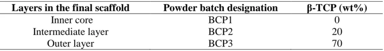
First, three batches of powders were prepared from HA and β-TCP powders, each batch being used for the different layers of the final scaffolds. For each batch, the required amounts of powders were weighed and ball-milled with zirconia balls. The composition of each batch is given in Table 1.
Table 1: β-TCP weight fraction (wt%) of the three BCP powder batches
Layers in the final scaffold Powder batch designation β-TCP (wt%)
Inner core BCP1 0
Intermediate layer BCP2 20
Outer layer BCP3 70
2.4. Fabrication of the scaffolds
Fig. 1 depicts a schematic diagram of the different preparation steps of the graded scaffold.
Each layer was prepared by a different process: gel-casting, gel-casting combined with
sacrificial template and solvent casting combined with particle leaching. The following sections
7
Fig. 1: Schematic diagram illustrating the main steps of the fabrication of the graded scaffold. In the bottom part, the specimens at the different steps of the process are graphically shown.
2.4.1. Step 1: BCP1 dense core by gel-casting
Ceramic slurries with an initial solid loading of 69 wt% were prepared from BCP1 powder and dispersed under magnetic stirring for 24 h. Agar was dissolved in deionized water (2 wt%), at 90°C for 10 minutes, to ensure a complete dissolution. The solution was then cooled down to 60°C and added to the dispersed ceramic slurries, at the same temperature. After agar addition, the BCP1 slurries reached a final solid loading of 62 wt%, while the agar concentration
decreased to 0.5 wt% (as respect to water). The suspensions were cast into cylindrical Plexiglas
moulds (12 mm internal diameter, 20 mm high). Casting was carried out under vacuum (about
10-2 Pa) to remove air bubbles entrapped into the ceramic suspensions. Gelation of the samples
occurred during slow cooling to room temperature. Samples were then slowly dried into humidity controlled chambers, in which the high initial relative humidity (RH > 90%) was slowly decreased after demoulding of the samples.
2.4.2. Step 2: BCP2 porous intermediate layer by gel-casting/sacrificial template
For the ceramic porous layer, ceramic slurries were prepared from BCP2 batch and dispersed under magnetic stirring for 48 hours. A fixed amount of sieved PE spheres was added to the
Step 1: Fabrication of inner core
Gel-casting
Step 2: Fabrication of intermediate layer
Gel-casting / Sacrificial template
• Preparation of the ceramic slurry • Addition of gelling agent • Mixing
• Casting into moulds • Gelation and demoulding • Partial drying
• Preparation of the ceramic slurry • Addition of porogen agents (PE spheres) • Addition of the gelling agent (agar) • Mixing
• Casting into moulds
• Gelation, demoulding and drying
• Debinding and sintering of the bilayer samples
Step 3: Fabrication of outer layer
Solvent casting / Particle leaching
• Dissolution of the polymer (PCL) in acetone • Addition of the ceramic powder
• Addition of the pore formers (NaCl) • Mixing
• Casting of the mixture around the previosly prepared bilayer samples
8 suspension, to obtain a porosity of 60 vol.% in the fired intermediate layer. Agar addition was
carried out following the same procedure described for BCP1 dense core. Then, BCP2
suspension was cast into cylindrical Plexiglas moulds (25 mm internal diameter, 15 mm high)
around the dense BCP1 core, which was already partially dried for one week. This procedure
was set up on the ground of the different shrinkage behaviour of the two layers. In fact, during
drying, BCP2 layer undergoes to a lower shrinkage as respect to BCP2, due to the presence of
the PE spheres. When simultaneously dried, an undesired separation between the two layers
occurred, thus requiring the two-steps fabrication process.
After drying, the bilayer samples were submitted to different heating steps of two hours each at
230°C, 300°C, 450°C, and 600°C, to gradually burn out the organic phase (PE and agar) without
collapse of the ceramic bodies. This thermal cycle was set up on the ground of TG-DTA curves
of PE spheres, as reported in a previous study [44]. The thermogravimetric curves showed that
PE burn out was accomplished at 550°C, through different decomposition steps at the
previously mentioned temperatures.The samples were then sintered at 1300°C for 3h (heating
and cooling rate of 1°C/min), being this thermal cycle defined on the ground of dilatometric
analyses, as described in 2.4.4.
2.4.3. Step 3: PCL/BCP3 porous external layer by salt leaching
First, 1.5 g of PCL pellets were dissolved in 10 mL acetone for 6 hours under vigorous magnetic
stirring. The required amount of the BCP3 powder was then added (40 wt% relatively to PCL content). The mixture was stirred for 24 hours for a complete homogenization. NaCl particles
were added in the mixture at a weight ratio of 9:1 (NaCl:PCL) under stirring. After homogenization of the NaCl particles in the mixture, this latter was poured around the BCP1/BCP2 sintered samples in plastic moulds (30 mm diameter, 20 mm high). Before the
9 PCL dissolved in acetone) for 5 seconds. This coating step was added to obtain a better adhesion
between the BCP2 and PCL/BCP3 layers. The three-layer samples were then air-dried for 24
hours at room temperature for complete evaporation of acetone. They were demoulded and immersed in deionized water for 4 days to leach out NaCl crystals. The water was refreshed
every 12 hours.
2.4.4. Fabrication and characterization of single pellets
In order to characterize properly the different layers, single cylindrical specimens
"representing" each layer of the final scaffold (i.e., dense BCP1, porous BCP2 and porous
PCL/BCP3) were fabricated with the processes described above (i.e., gel-casting, gel-casting
with PE spheres and solvent casting/salt leaching respectively).
In the case of BCP1, gelcast bars were prepared and submitted to dilatometry (Netzsch 402E). The following conditions were applied: peak temperature of 1300°C, heating and cooling rate of 1°C/min, soaking time of 3 h. On the ground of this analysis, both BCP1 and BCP2 were
sintered according to this thermal cycle.
The phase composition of the single samples was analysed by XRD, under the same conditions
described for the powders.
The densities were estimated from weight and geometrical measurements and the relative densities were calculated considering the densities of fully dense samples and pure phases: 3.15 g.cm-3 for HA, 3.07 g.cm-3 for β-TCP and 1.15 g.cm-3 for PCL.
The microstructures were observed under SEM with a voltage of 12 kV. Before observation,
the samples were mirror polished and metallized with a chromium coating. The grain size was determined by linear intercept method on different SEM images using Image J software. The results of these characterizations are presented in section 3.3.
10
2.5. In vitro dissolution test of the three-layer scaffolds
2.5.1. Immersion tests
The three-layer scaffolds were immersed in a 0.1 M tris(hydroxymethyl)aminomethane (C4H11NO3, TRIS) solution, buffered at pH 7.4 (physiological pH) by dropwise addition of
nitric acid. Immersion tests were performed in a dissolution tester PTWS 1210 (Pharmatest,
Germany). The temperature of the TRIS solutions was maintained at 37°C by a thermostatic
bath and the solutions were constantly stirred at 50 rpm with blades. In total, 12 samples were immersed for four different durations: 2, 6, 11 and 17 days (n=3 different samples tested per time point). A solution volume to sample weight ratio of 20 mL/g was chosen. The average volume of solution for each sample was 146.6 mL. Renewal of the immersion solution was made every 24 hours by the mean of peristaltic pumps: one pump removed 100 mL of solution (out of a mean volume of 145 mL) and the other one introduced 100 mL of freshly prepared TRIS solution. These test conditions, including the renewal of the solution, enable to model physiological conditions as closely as possible (constant temperature, pH and constant composition of biological fluids).
2.5.2. Characterization of the scaffolds
The scaffolds were characterized before and after immersion. At each time-point, they were removed from the solutions, dried at 37°C until constant weight, weighed, and measured. Variation of weight and apparent density was calculated with the equation (1):
𝛥𝑋 = 100 (𝑋𝑖𝑛 − 𝑋𝑓𝑖𝑛
𝑋𝑖𝑛 ) (1)
where ΔX is the weight loss (or apparent density) in percent, Xin and Xfin are the initial and final
weight (or apparent density) of the scaffolds.
Evolution of the phase composition was analysed by XRD (Brucker D8 Advance, equipped with a LynxEye detector) with Cu Kα radiation (λ = 0.15406 nm). Collection of data was done
11 along the angular range 4°-65°, with a step size of 0.02° and a time per step of 0.4 s. To avoid cutting the samples, the whole surface of each scaffold was scanned in one single analysis. Therefore, the resulting patterns provide an average composition of the three layers.
The whole microstructure of the samples was investigated by X-ray tomography with a standard laboratory tomograph (Phoenix v | Tome | x, General Electric), equipped with a Varian Paxscan detector (1920x1536 pixels). The following scanning conditions were used: voxel size of 13 µm, scan time of 333 ms, 1000 radiographs per scan, intensity of 80 µA and voltage of 140 kV. The volumes were reconstructed from radiographs thanks to a commercial software coupled to the equipment. They were then analysed using ImageJ software.
Finally, the surface of each layer of the scaffolds was observed by SEM.
3. Results and discussion
3.1. Characterization of the as-received powders
The two powders were composed of HA and β-TCP crystalline phases respectively, as declared by the supplier and confirmed by XRD analyses (not shown).
In Fig. 2a and 2b, the SEM micrographs of as-received HA and β-TCP powders are depicted,
showing a not regular shape of the primary particles, characterized by a micronic size and a
certain agglomeration.
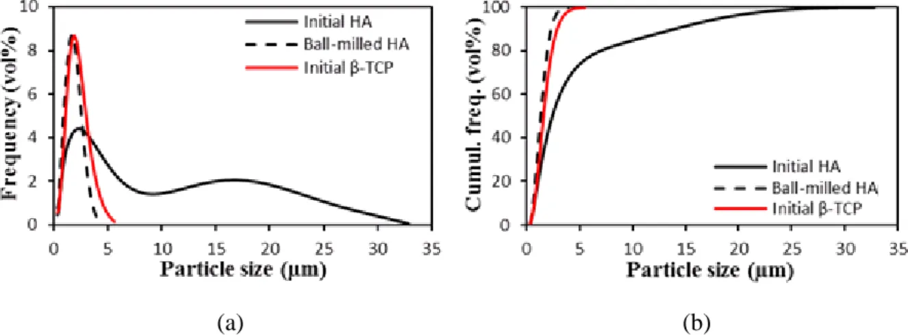
Fig. 3 shows the particle size distribution of the same powders. HA presents a bimodal
distribution, with d10, d50 and d90 (i.e. the agglomerate sizes corresponding to 10%, 50% and
90% of the cumulative frequency distribution) equal to 0.8, 2.5, and 14.7 m respectively. On the opposite, as-received -TCP was characterized by a narrower particle size distribution, with
12 ball-milling for 1 h, HA reached a particle size distribution close to -TCP,with similar d10, d50
and d90 values of 0.7, 1.7 and 3.1 m, respectively.
(a) (b)
Figure 2: FE-SEM micrograph of the (a) HA and (b) β-TCP starting powders. Insets: higher magnification micrographs.
(a) (b)
Figure 3: Frequency (a) and cumulative frequency (b) distributions of as-received and ball-milled HA and of as-received β-TCP.
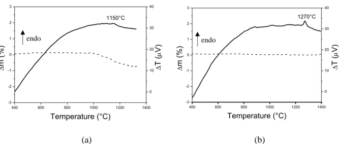
The DTA curves of the two as-received powders are presented in Fig. 4. In the case of HA (a), a small endothermal peak was observed at around 1150°C. In order to ascribe such a thermal signal to decomposition phenomena, HA powder was calcined at different temperatures in the range 1000°C - 1300°C. Even if XRD were carried out in the whole 5-70° 2 range, only the
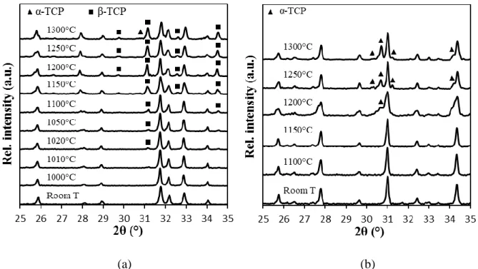
13 25-35° 2 range is depicted in the following Figures, in order to evidence the most intense calcium phosphates peaks and their evolution. Fig. 5(a) reveals that HA undergoes partial decomposition into β-TCP starting from 1010°C. The relative intensity of the β-TCP peaks increases as the calcination temperature raises. The presence of β-TCP from 1010°C indicates the presence of a small amount of Ca-deficient apatite (CDA) Ca10-x-y(HPO4)x(PO4)
6-x-y(CO3)y(OH)2-x-y-2z(CO3)z (having a Ca/P ratio lower than the stoichiometric value of 1.67) in
the commercial powder used in this study, as already found by Yang et al. [45]. CDA has a crystal structure similar to stoichiometric HA and thus cannot be distinguished from HA by XRD. It decomposes into HA and β-TCP at temperatures above 800°C [10, 46]. Therefore, it is possible to assign the small endothermal peak at 1150°C in Fig. 4a to the decomposition of CDA into HA and -TCP. In addition, in the same Figure, the TG curve shows a certain mass loss (of about 1%) starting from about 1050°C, which could be imputed to the continuous dihydroxylation of CDA/HA towards -TCP.
(a) (b)
Figure 4: DTA-TG curves of (a) HA and (b) β-TCP powders. The two main peaks with the corresponding temperatures are identified.
Considering the DTA-TG curves of -TCP, we can observe a clear endothermal peak at 1270°C
(Fig. 4b), while no mass loss was detected. From XRD analysis (Fig. 5b), we observe that
α-400 600 800 1000 1200 1400 -3 -2 -1 0 1 2 3 Temperature (°C) 1150°C 0 10 20 30 40 T ( V) m (%) endo 400 600 800 1000 1200 1400 -3 -2 -1 0 1 2 3 T ( V) m (%) Temperature (°C) 1270°C 0 10 20 30 40 endo
14
TCP phase first appeared at 1200°C and was clearly detected at 1250°C. Therefore, in spite of
a certain discrepancy, the β/α-TCP phase transformation can explain the DTA signal. Previous
investigations attested the -TCP phase transformation into the -polymorph at temperatures
above 1110°C [47-50].
A small amount of α-TCP was also detected in the HA powder calcined at 1300°C (Fig. 5a). We can hypothesize that a small amount of the β-TCP phase resulting from the previous
decomposition of the CDA/HA powder was transformed into α-TCP.
(a) (b)
Figure 5: XRD patterns of (a) HA calcined from 1000 to 1300°C, showing the formation of - and β-TCP (the non-indexed peaks correspond to HA) and (b) β-TCP calcined from 1100 to
1300°C showing its conversion into α-TCP (the non-indexed peaks correspond to β-TCP)
3.2. Sintering behaviour of the BCP1 bars
Dilatometric analyses were carried out on BCP1 gelcast bars. According to this
characterization, the sintering cycle has been defined and applied to both BCP1 and BCP2
samples, as the bilayer structure (made by BCP1 / BCP2 layers) is sintered under the same
15
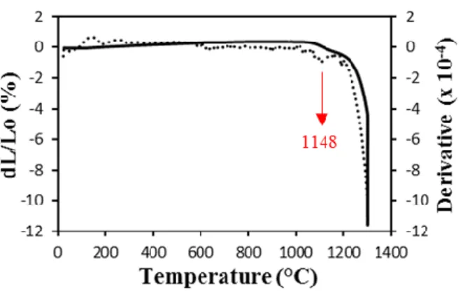
As we can see in Fig. 6, the onset shrinkage temperature was observed at 1018°C. As mentioned
in the previous section, this temperature corresponds to the beginning of CDA/HA
decomposition, which thus overlaps with the beginning of densification. The derivative curve
showes an inflection point at 1148°C, which could again be related to the partial decomposition
of CDA into β-TCP, on the ground of previous DTA (Fig. 4a) and XRD results (Fig. 5a). BCP1
bars underwent a total linear shrinkage of 11.6%. The major contribution of this shrinkage (7.6%) took place during the isothermal step at 1300°C. After sintering, the samples reached a fired density of (80.1 ± 1.0)%, which is quite low in comparison with literature [51, 52]. This incomplete densification can be partially explained by the gel-casting process, and precisely by the use of organic matter as gelling agent, which could give rise to a certain residual porosity in the sintered microstructure [53, 54]. However, in our case, the amount of agar was quite low
(0.5 wt% as respect to water). Therefore, to increase the density, the whole gel-casting process
has to be improved, in particular way by increasing the solid loading of the ceramic particles in
the slurries [34].
Figure 6: Linear shrinkage (solid line) and derivatives curves (dashed lines) versus temperature of the BCP1 single bar. One peak, corresponding to the partial decomposition of
16
3.3. Characterization of the single pellets
The results presented here refer to the single pellets "representing" each layer of the three-layer scaffold (i.e., dense BCP1, macroporous BCP2 and macroporous PCL/BCP3).
The relative densities of the pellets were (80.1 ± 1.0) %, (34.6 ± 1.6) % and (23.8 ± 1.8) % for BCP1, BCP2 and PCL/BCP3 samples, respectively. Despite the incomplete sintering of the all-ceramic samples, a gradient of porosity was obtained from the BCP1 (i.e., the internal layer of the scaffold) to the PCL/BCP3 layer (i.e., the external layer of the scaffold). The volume
fraction of pores measured in the BCP2 pellets (i.e., 65.4%) was slightly higher than the volume
fraction of PE spheres introduced in the suspensions during the gel-casting process (i.e., 60
vol%): the difference was due to the residual pores left by incomplete sintering. The volume
fraction of pores in PCL/BCP3 pellets (i.e., 76.2 %) is also in agreement with the volume
fraction of NaCl porogens added in the samples (i.e., 79%). These results show that the two processes used to prepare the porous layers are effective to obtain the expected volume fraction of pores.
In a previous work [55], we tested the mechanical performance of gel-cast microporous HA samples (i.e., samples having same composition and residual porosity as BCP1) : the compressive strength determined (up to 340 MPa) was in line with the values commonly reported for cortical bone [56], suggesting a possible mechanical function of the core layer in our scaffold.
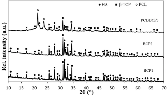
The XRD patterns of the single pellets are depicted in Fig. 7. The three patterns showed the presence of HA and β-TCP phases. In the case of the PCL/BCP3 specimen, the XRD pattern confirmed the presence of PCL thanks to its two main peaks at 2θ = 21.3° and 23.7°, corresponding to (110) and (200) crystallographic planes respectively [15]. No peak
corresponding to the α-TCP phase was detected, contrary to what observed for both HA and
17
high cooling rate (20°C/min) in order to retain the metastable α-TCP phase and highlight the
transformations occurring in the samples at high temperatures. On the contrary, the absence of α-TCP in the BCP1 and BCP2 single pellets (Fig. 7) can be explained by the low cooling rate (1°C/min) applied on purpose to enable the reversible α-to-β-TCP transformation to take place
[42]. Thus, biphasic calcium phosphate samples (containing only HA and β-TCP) could be
obtained.
After fabrication, the samples exhibited a gradation of HA/β-TCP ratio from the internal to the
external layer: in fact, the estimated value of β-TCP fraction gradually increased (from 42, to
53 and finally to 68 wt%) moving from the core to the outer layer. In the case of the BCP1 and
BCP2 ceramic layers, the β-TCP content is coherent with the important decomposition of HA
observed after the calcination treatments of the initial powder (see section 3.2). Despite this
phenomenon, affecting especially the dense core, a gradation of composition through the layers
is successfully achieved.
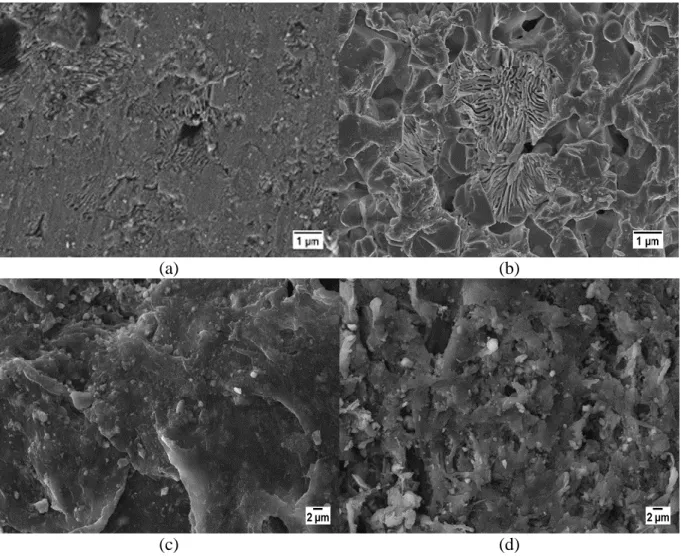
18 The SEM micrograph of each pellet is shown in Fig. 8. The dense BCP1 polished surface (Fig.
8a) exhibited well-sintered grains with an average size of (3.2 ± 1.2) µm. The residual
micrometer-sized pores left by incomplete sintering were also visible. Fig. 8b shows the fracture
surface of the BCP2 specimen. The macropores had a spherical shape with an average size of
(245 ± 21) µm, which is in good agreement with the size of the sieved PE spheres. In addition,
we can observe the numerous interconnections present among the macropores, with size
ranging from one to a few tenths of microns. Fig. 8c shows the fracture surface of the
PCL/BCP3 composite. Here is clearly visible the irregular, square-shape of the macropores left
by the NaCl crystals, due to the grinding and sieving procedure used to produce the granular
salt. The average pore size was (229 ± 46) µm, in a good agreement with the size of NaCl
granules. Fig. 8d shows a magnified image of the polymer strut between the pores, showing the
presence of well-dispersed CaP particles within the PCL matrix. The size of the ceramic
particles was in the range 0.5-2 µm, in good agreement with their granulometric data, thus
suggesting a good dispersion of the CaP powder in the polymer solution. Residual pores having
19 Figure 8: FE-SEM micrographs of (a) polished and thermally etched BCP1 surface, (b)
fracture surface of the BCP2 specimen, (c) fracture surface of the PCL/BCP3 composite, (d)
magnified image of the polymer strut between the macropores in the PC/BCP3 composite.
3.4. Characterization of the three-layer scaffolds
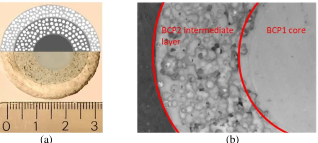
In Fig. 9a, a scheme of the three-layer graded structure is overlapped with the experimentally developed scaffold, showing the good joining of the three different layers, while the stereomicroscopy image in Fig. 9b highlights the continuous and crack-free interface between the two ceramic layers. Moreover, the comparison between the scheme and the picture in Fig. 9a shows that our approach was successful to produce a three-layer scaffold with good interfaces between the layers. In particular, the polymer adhered strongly to the ceramic porous layer. This is a key point for the structures developed in this work.
A
B
C
D
20 (a) (b)
Figure 9: (a) Digital picture (bottom part) and schematic illustration (upper part) of the three-layer scaffold with BCP1, BCP2 and PCL/BCP3 three-layers from the centre to the periphery and (b) stereomicroscope image of a polished surface evidencing the interface between the BCP1
and BCP2 layers
3.5. Dissolution tests of the scaffolds
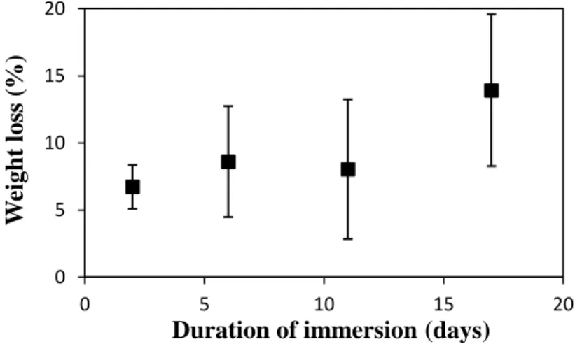
Fig. 10 shows the evolution of the three-layer scaffold’s weight during immersion in TRIS. The samples underwent significant weight losses during the two first days (average weight loss of 6.7% for samples immersed for 2 days). Then the graph shows a quite constant weight loss
between 2 and 11 days (-8.0 % for samples immersed for 11 days) and then an increase in
weight loss from 11 days. At the end of the test, the samples immersed for 17 days had lost
around 13.9% of their initial weight.
Each scaffold was analysed by XRD on the lateral (flat) surface of the cylindrical sample before and after immersion. Table 2 summarizes the evolution of the weight fraction of β-TCP,
measured on a same sample before and after immersion. As explained in section 2.5.2, the
resulting XRD patterns characterized an average of the phase composition on the whole surface (i.e., including the three layers). For this reason, the values of the weight fraction given in Table 2 cannot be directly compared to weight ratio calculated for each layer (section 3.3). For the 4 samples tested before immersion, small variations can be observed from one sample to another.
21 However, these differences were not significant. Comparing the evolution of each sample during immersion, the weight fractions of β-TCP did not vary for immersion times of 2, 6 and 11 days. On the opposite, this weight fraction decreased significantly after 17 days of immersion, suggesting the partial dissolution of the -TCP phase. Besides, this dissolution is consistent with the weight loss observed between 11 and 17 days (Fig. 10).
Figure 10: Weight loss of the scaffolds at different time-points of the test
Table 2: Evolution of β-TCP weight fraction in the whole scaffold before and after immersion in TRIS for each duration of immersion. These values were obtained for one scaffold per
immersion time. Duration of immersion β-TCP (wt%) before immersion β-TCP (wt%) after immersion 2 days 53 53 6 days 55 55 11 days 56 56 17 days 56 48
Fig. 11a and 11b show the micrographs of the surfaces of the BCP1 layer of the scaffolds immersed for 11 days and 17 days. Locally, degraded zones were clearly visible, especially
after 17 days of immersion. The presence of degradation "pits" at different locations on the surface evidences a selective degradation of the surface, possibly related to a dissolution phenomenon. Similar observations can be made on the BCP2 surfaces (not shown here). The
0 5 10 15 20 0 5 10 15 20 W eigh t loss (% )
22 presence of local degradation pits after immersion has already been observed in the literature for biphasic CaP materials such as HA/β-TCP [57] or β/α-TCP [58]. Fig. 11c and 11d depict some representative SEM images of the surfaces of the PCL/BCP3 layer of the scaffolds immersed for 11 and 17 days scaffolds, respectively. No significant changes appeared in the
morphology of the layer after 11 days of immersion with respect to the starting one (see Fig. 8c). On the opposite, the scaffold immersed for 17 days presented a rougher aspect. This
characteristic has already been observed for PCL/CaP composites after immersion in different media [60, 61]. Slightly less CaP particles seemed present at the surface of the immersed scaffolds as compared with the initial state (Fig. 8d), indicating their partial dissolution.
(a) (b)
(c) (d)
Figure 11: SEM micrographs of the BCP1 surface (a) from the scaffold immersed during 11 days and (b) the scaffold immersed for 17 days; of the PCL/BCP3 surface from (c) the
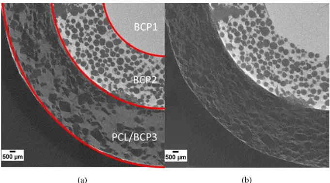
23 X-Ray tomography slices of the 3D images of a scaffold immersed for 17 days before and after
immersion are shown in Fig. 12. From these images, the targeted gradation of porosity is well visible. The pores were correctly dispersed in the two BCP2 and PCL/PCP3 layers and the continuous interfaces between the different layers are here again well evidenced. After immersion, no significant changes were visible for the BCP1 and BCP2 layers, while the PCL/BCP3 layer was clearly less dense after a 17 days immersion, as visible from the different
grey level in the two external layers. Therefore, X-ray tomography confirmed that the loss of
weight observed during the test mainly originated from the PCL/BCP3 layer. Despite the important dissolution of the external polymer layer, it is important to underline that even after 17 days of immersion, it was still joined to the ceramic part, further highlighting the effective interface between the two layers.
(a) (b)
Figure 12: Slice of 3D X-Ray Tomography images of a scaffold (a) before and (b) after immersion for 17 days in TRIS. The ceramic phase has a larger absorption of X-ray as
24 Many authors have performed in vitro dissolution tests of CaP-based materials. However, the test conditions differ importantly from one work to another one (immersion solution, stirring, refresh of solution) and have an influence on the results obtained. It is necessary to choose carefully these parameters in relation with the phenomena to investigate [61]. In this study, the TRIS solution which does not contain Ca2+ nor PO43- ions was chosen to favour dissolution
phenomena. Renewal of solution allows being as close as possible to the physiological conditions (constant temperature, pH and composition of biological fluids).
The weight losses measured prove that a dissolution phenomenon took place from the beginning of the test. Tomography and SEM strengthen this idea showing a matter loss in the bulk and at the surface.
The results from XRD and SEM evidence a preferential dissolution of β-TCP as compared with HA. It agrees with previous results reported for BCP ceramics [57, 62, 63] and the higher solubility of β-TCP in comparison with HA is well-known. This feature and the large dissolution observed in the external layer appear in agreement with the targeted multi-functionality of our scaffolds (i.e., a bioresorbable β-TCP-rich layer in contact with bone coupled with a HA-rich inner layer with lower bioresorption). However, the high HA decomposition in the BCP1 and BCP2 layers during sintering has changed the targeted compositional gradient. The less marked gradation in HA/β-TCP ratio between the layers has probably led to a less marked differentiated dissolution between the layers. It can be noted that a more marked gradation of HA/β-TCP ratio between the layers would be beneficial to emphasize the functional gradient character of the scaffolds. For this purpose, a better control of the composition of the sintered samples appears necessary.
3D images suggest that the largest part of the weight loss can be attributed to a dissolution of the external PCL/BCP3 layer. The low degradation rate of PCL is often mentioned in the literature [15, 64]. However, numerous studies report a higher dissolution rate for PCL/CaP
25 composites [61, 65, 66], linked to the higher dissolution rate of CaP phases in comparison with the PCL alone [66].
It is also difficult to conclude about the respective influence of the porosity (pore size and pore volume fraction) and the HA/β-TCP ratio on the overall dissolution behaviour. To obtain more information, dissolution tests could be performed on different scaffolds with only one variable parameter (i.e., either a porosity gradient only or a compositional gradient only and not both). The signs of dissolution detected are more marked for the scaffolds after 17 days of immersion than for the other ones, suggesting an acceleration of the dissolution phenomenon after 11 days of immersion in the in vitro conditions chosen in this study. To investigate better the long term evolution of the scaffolds, a longer duration of the test would be necessary with time-points of several months [67].
5. Conclusion
In this work, a three-layer graded scaffold was successfully obtained via gel-casting and solvent casting/particle leaching processes. The aim was to obtain a gradation of composition and porosity from a dense core to a porous external layer. In addition, an external polymer layer was strongly joined to an inner ceramic one, being a strong point of innovation in this structure as compared to previous literature. Characterization of the scaffolds demonstrated a clear gradient of porosity between the layers, whereas the gradation of phase composition was less marked than the targeted one, because of the partial HA decomposition during sintering. The fabrication process can be improved to better control the final composition of the scaffolds and to achieve a stronger gradation in composition after sintering. An in vitro dissolution test was conducted by immersion of scaffolds in TRIS solution at 37°C for durations ranging from 2 to 17 days. Different signs of dissolution were found in the three layers. The results give some indications about different behaviours in the different layers. This fits with the targeted
multi-26 functionality of the graded samples, with a resorbable external layer in contact with bone and a core devoted to the mechanical function. However, longer dissolution tests and other in-vitro investigations on the immersed samples are needed to understand better the long-term behaviour and to deepen the dissolution mechanisms of the different layers constituting the scaffolds. As a final consideration, the proposed scaffold can be considered as a model system, opening the way to the design and fabrication of further innovative architectures with targeted multi-functionalities.
6. Conflict of interest None
7. Acknowledgments
This work was partly supported by COST Association in the frame of the COST Action MP1301 NEWGEN "New generation biomimetic and customized implants for bone engineering". The authors want to acknowledge Labormet Due srl, Torino, Italy, for the images of stereomicroscopy and Jérome Adrien, MATEIS, for the X-ray tomography.
8. References
[1] M. Bohner, Calcium from ceramics orthophosphates to calcium phosphate in medicine: cements, Int. J. Care Injured (2000) S-D3747.
[2] R.Z. LeGeros, Properties of osteoconductive biomaterials: calcium phosphates, Clin.
Orthop. Relat. Res. 395 (2002) 81-98.
[3] C. Rey, C. Combes, C. Drouet, M.J. Glimcher, Bone mineral: update on chemical composition and structure. Osteoporos Int. 20 (2009) 1013–1021.
27 [4] A.J. Wagoner-Johnson, B.A. Herschler, A review of the mechanical behavior of CaP and CaP/polymer composites for applications in bone replacement and repair, Acta Biomater. 7 (2011) 16-30.
[5] H.C.S. Beekmans, G.J. Meijer, R. Barkhuysen, et al., The hydroxylapatite-bone interface: 10 years after implant installation, Int. J. Oral Maxillofac. Surg. 37 (2008) 768-772.
[6] J. Lu, M. Descamps, J. Dejou et al., The biodegradation mechanism of calcium phosphate biomaterials in bone, J. Biomed. Mater. Res. Appl. Biomater. 63 (2002) 408-412.
[7] M. Jarcho, R.L. Salsbury, M.B. Thomas, et al., Synthesis and fabrication of β-tricalcium phosphate (whitlockite) ceramics for potential prosthetic applications, J. Mater. Sci. 14 (1979) 142-150.
[8] P. Miranda, A. Pajares, E. Saiz, et al., Mechanical properties of calcium phosphate scaffolds fabricated by robocasting, J. Biomed. Mater. Res. 85A (2008) 218-227.
[9] J.-M. Bouler, R.Z. LeGeros, G. Daculsi, Biphasic calcium phosphates: influence of three synthesis parameters on the HA/b-TCP ratio, J. Biomed. Mater. Res. 51 (2000) 680-684. [10] R.Z. LeGeros, S. Lin, R. Rohanizadeh, et al., Biphasic calcium phosphate bioceramics: preparation, properties and application, J. Mater. Sci. Mater. Med. 14 (2003) 201-209.
[11] Peroglio, L. Gremillard, J. Chevalier, et al., Toughening of bio-ceramics scaffolds by polymer coating, J. Eur. Ceram. Soc. 27 (2007) 2679-2685.
[12] P. Gentile, V. Chiono, I. Carmagnola, et al., An overview of poly(lactic-co-glycolic) acid (PLGA)-based biomaterials for bone tissue engineering, Int. J. Mol. Sci. 15 (2014) 3640-3659.
28 [13] F. von Burkersroda F, L. Schedl, A. Göpferich, Why degradable polymers undergo surface erosion or bulk erosion, Biomaterials 23 (2002) 4221-4231.
[14] K.J. Lowry, K.R. Hamson, L. Bear, et al., Polycaprolactone/glass bioabsorbable implant in a rabbit humerus fracture model, J. Biomed. Mater. Res. 36 (1997) 536-541.
[15] I. Castilla-Cortázar, J. Más-Estellés, J.M. Meseguer-Dueñas, et al., Hydrolytic and enzymatic degradation of a poly(ε-caprolactone) network, Polym Degrad. Stab. 97 (2012) 1241-1248.
[16] A. Bignon, J.J. Chouteau, J. Chevalier, et al., Effect of micro- and macroporosity of bone substitutes on their mechanical properties and cellular response, J. Mater. Sci.Mater. Med. 14 (2003) 1089-1097.
[17] K.A. Hing, B. Annaz, S. Saeed, et al., Microporosity enhances bioactivity of synthetic bone graft substitutes, J. Mater Sci. Mater. Med. 16 (2005) 467-475.
[18] D.M. Liu, Influence of porosity and pore size on the compressive strength of porous hydroxyapatite ceramic, Ceram. Int. 23 (1997) 135-139.
[19] V. Karageorgiou, D. Kaplan, Porosity of 3D biomaterial scaffolds and osteogenesis,
Biomaterials 26 (2005) 5474-5491.
[20] M. Bohner, G. Baroud, A. Bernstein et al., Characterization and distribution of mechanically competent mineralized tissue in micropores of β-tricalcium phosphate bone substitutes, Mater. Today 20 (2017) 106-115.
[21] M. Alshaaer, M.H. Kailani, N. Ababneh, Fabrication of porous bioceramics for bone tissue applications using luffa cylindrical fibres (LCF) as template, Process Appl. Ceram. 11 (2017) 13-20.
[22] S.K. Lan Levengood, S.J. Polak, M.B. Wheeler, et al., Multiscale osteointegration as a new paradigm for the design of calcium phosphate scaffolds for bone regeneration,
29 [23] B.-S. Kim, H. J. Kang, J. Lee, Improvement of the compressive strength of a cuttlefish bone-derived porous hydroxyapatite scaffold via polycaprolactone coating, J. Biomed. Mater.
Res. B 101 (2013) 1302-1309.
[24] J. Brzezińska-Miecznik, B. Macherzyńska, R. Lach, et al., The effect of calcination and zirconia addition on HAp hot pressed materials, Ceram. Int. 40 (2014) 15815-15819.
[25] G. Batin, C. Popa, L. Brânduşan, et al., Mechanical properties of Ti/HA functionally graded materials for hard tissue replacement, Powder Metall. Progr. 11 (2011), 206-209. [26] C. Chu, J. Zhu, Z. Yin, et al., Optimal design and fabrication of hydroxyapatite/Ti asymmetrical functionally graded biomaterial, Mater. Sci. Eng. A 348 (2003) 244-250.
[27] M.A.F. Afzal, P. Kesarwani, K.M. Reddy, et al., Functionally graded hydroxyapatite-alumina-zirconia biocomposite: Synergy of toughness and biocompatibility, Mater. Sci. Eng. C 32 (2012) 1164-1173.
[28] H.B. Guo, K.A. Khor, Y.C. Boey, et al., Laminated and functionally graded hydroxyapatite/yttria stabilised tetragonal zirconia composite fabricated by Spark Plasma Sintering, Biomaterials 24 (2003) 667-675.
[29] Q. Wang, Q. Wang, C. Wan, Preparation and evaluation of a biomimetic scaffold with porosity gradients in vitro, Anais da Academia Brasileira de Ciências 84 (2012) 9-16.
[30] H. Lee, T.S. Jang, J. Song, The production of porous hydroxyapatite scaffolds with graded porosity by sequential freeze-casting, Materials 10 (2017) 367-139.
[31] S. Chamary, D. Hautcoeur, J.-C. Hornez, et al., Bio-inspired hydroxyapatite dual core-shell structure for bone substitutes, J. Eur. Ceram. Soc. 37 (2017) 5321-5327.
[32] J. Yang, J. Yu, Y. Huang, Recent developments in gelcasting of ceramics, J. Eur. Ceram.
Soc. 31 (2011) 2569-5391.
30 [34] B. Chen, Z. Zhang, J. Zhang, et al., Fabrication and mechanical properties of β-TCP pieces by gel-casting method, Mater. Sci. Eng. C 28 (2008) 1052-1056.
[35] B. Flautre, M. Descamps, C. Delecourt, et al., Porous HA ceramic for bone replacement: Role of the pores and interconnections – experimental study in the rabbit, J. Mater. Sci. Mater.
Med. 12 (2001) 679-682.
[36] G. Lehmann, P. Palmero, I. Cacciotti, et al., Design, production and biocompatibility of nanostructured porous HAp and Si-HAp ceramics as three-dimensional scaffolds for stem cell culture and differentiation, Ceramics-Silikáty 54 (2010) 90–96.
[37] S. Alonso-Sierra, R. Velázquez-Castillo, B. Millán-Malo, R. Nava, L. Bucioc, A. Manzano-Ramírez, H. Cid-Luna, E.M. Rivera-Muñoz, Interconnected porosity analysis by 3D X-ray microtomography and mechanical behavior of biomimetic organic-inorganic composite materials, Mater. Sci. Eng. C. 80 (2017) 45-53.
[38] C.-J. Liao, C.F. Chen, J.H. Chen, et al., Fabrication of porous biodegradable polymer scaffolds using a solvent merging/particulate leaching method, J. Biomed. Mater. Res. 62 (2002) 676–681.
[39] N. Thadavirul, P. Pavasant, P. Supaphol, Improvement of dual-leached polycaprolactone porous scaffolds by incorporating with hydroxyapatite for bone tissue regeneration, J.
Biomater. Sci. Polym. Ed. 25 (2014) 1986-2008.
[40] M. Lombardi, P. Palmero, K. Haberko, et al., Processing of a natural hydroxyapatite powder: from powder optimization to porous bodies development, J. Eur. Ceram. Soc. 31 (2011) 2513–2518.
[41] NIH National Institute of Health, Image J. Available on: http://imagej.nih.gov/ij
[42] O. Brown, M. Mc Afee, S. Clarke, et al., Sintering of biphasic calcium phosphate, J. Mater.
31 [43] M.-K. Ahn, Y.-W. Moon, Y.-H. Koh, et al., Production of highly porous triphasic calcium phosphate scaffolds with excellent in vitro bioactivity using vacuum-assisted foaming of ceramic suspension (VFC) technique, Ceram. Int. 39 (2013) 5879-5885.
[44] M. Lombardi, V. Naglieri, J.-M. Tulliani, et al., Gel-casting of dense and porous ceramics by using a natural gelatine, J. Porous. Mater. 16 (2009) 393-400.
[45] H.Y. Yang, S.F. Yang, X.P. Chi, et al., Sintering behaviour of calcium phosphate filaments for use as hard tissue scaffolds, J. Eur. Ceram. Soc. 28 (2008) 159-167.
[46] J. Zhou, X. Zhang, J. Chen, et al., High temperature characteristics of synthetic hydroxyapatite, J. Mater. Sci. Mater. Med. 4 (1993) 83-85.
[47] P.M.C. Torres, J.C.C. Abrantes, A. Kaushal, et al., Influence of Mg-doping, calcium pyrophosphate impurities and cooling rate on the allotropic α↔β tricalcium phosphate phase transformations, J. Eur. Ceram. Soc. 36 (2016) 817–827.
[48] J.C. Elliott, Structure and Chemistry of the Apatites and Other Calcium Orthophosphates, Elsevier, Amsterdam, 1994.
[49] R. Enderle, F. Götz-Neunhoeffer, M. Göbbels, et al., Influence of magnesium doping on the phase transformation temperature of β-TCP ceramics examined by Rietveld refinement,
Biomaterials 26 (2005) 3379–3384.
[50] H.-S. Ryu, H.-J. Yoon, K.S. Hong, et al., An improvement in sintering property of β tricalcium phosphate by addition of calcium pyrophosphate, Biomaterials 23 (2002) 909-914. [51] M. Akao, H. Aoki, K. Kato, Mechanical properties of sintered hydroxyapatite for prosthetic applications, J. Mater. Sci. 16 (1981) 809-812.
[52] R. Halouani, D. Bernache-Assolant, E. Champion, et al., Microstructure and mechanical properties of hot pressed hydroxyapatite ceramics, J. Mater. Sci. 5 (1994) 563–568.
32 [53] G.S. Koçlar, Gelcasting of alumina ceramics with gelatin and carrageenan gum and investigation of their mechanical properties, available at http://hdl.handle.net/11147/3571, (2013) (Master of Science Thesis).
[54] C. Bartuli, E. Bemporad, J.M. Tulliani, et al., Mechanical properties of cellular ceramics obtained by gel casting: characterization and modeling, J. Eur. Ceram. Soc. 29 (2009) 2979-2989.
[55] P. Marcassoli, M. Cabrini, J. Tirillò, et al., Mechanical characterization of hydroxyapatite micro/macro-porous ceramics obtained by means of innovative gelcasting process, Key Eng.
Mater. 417-418 (2010) 565-568.
[56] C. Öhman, M. Baleani, C. Pani, et al., Compressive behaviour of child and adult cortical bone, Bone 49 (2011) 769-776.
[57] S. Raynaud, E. Champion, J.P. Lafon, et al., Calcium phosphate apatites with variable Ca/P atomic ratio III. Mechanical properties and degradation in solution of hot pressed ceramics, Biomaterials 23 (2002) 1081-1089.
[58] F.-H. Lin, C.-J. Liao, K.-S. Chen, et al., Petal-like apatite formed on the surface of tricalcium phosphate ceramic after soaking in distilled water, Biomaterials 22 (2001) 2981-2992.
[59] Y. Wang, L. Liu, S. Guo, Characterization of biodegradable and cytocompatible nano-hydroxyapatite/polycaprolactone porous scaffolds in degradation in vitro, Polym. Degrad. Stab. 95 (2010) 207-213.
[60] F. Wu, C. Liu, B. O'Neill, et al., Fabrication and properties of porous scaffold of magnesium phosphate/polycaprolactone biocomposite for bone tissue engineering, Appl. Surf.
Sci. 258 (2012) 7589-7595.
[61] M. Gallo, S. Tadier, S. Meille, et al., Resorption of calcium phosphate materials: considerations on the in vitro evaluation, J. Eur. Ceram. Soc. 38 (2018) 899-914.
33 [62] S. Sánchez-Salcedo, F. Balas, I. Izquierdo-Barba, et al., In vitro structural changes in porous HA/b-TCP scaffolds in simulated body fluid, Acta Biomater. 5 (2009) 2738-2751. [63] C. Shuai, P. Li, J. Liu, et al., Optimization of TCP/HAP ratio for better properties of calcium phosphate scaffold via selective laser sintering, Mater. Charact. 27 (2013) 23-31. [64] J. Peña, T. Corrales, I. Izquierdo-Barba, et al., Long-term degradation of poly(ε- caprolactone) films in biologically related fluids, Polym. Degrad. Stab. 91 (2006) 1424-1432. [65] R. Nithya, N. Meenakshi Sundaram, Biodegradation and cytotoxicity of ciprofloxacin loaded hydroxyapatite-polycaprolactone nanocomposite film for sustainable bone implants, Int.
J. Nanomedicine 10 (2015) 119-127.
[66] K. Ang, K.F. Leong, C.K. Chua, et al., Compressive properties and degradability of poly(ε-caprolatone)/hydroxyapatite composites under accelerated hydrolytic degradation, J. Biomed.
Mater. Res. A 80 (2007) 655-660.
[67] M. Gallo, S. Tadier, S. Meille, et al., In vitro evolution of resorbable brushite cements: a physico-chemical, micro-structural and mechanical study, Acta Biomater. 53 (2017) 515-525.
34 Table’s and figure’s captions
Table 1: β-TCP weight fraction (wt%) of the three BCP powder batches
Table 2: Evolution of β-TCP weight fraction in the whole scaffold before and after immersion in TRIS for each duration of immersion. These values were obtained for one scaffold per immersion time.
Figure 1: Schematic diagram illustrating the main steps of the fabrication of the graded scaffold. In the bottom part, the specimens at the different steps of the process are graphically shown.
Figure 2: FE-SEM micrographs of the (a) HA and (b) β-TCP starting powders. Insets : higher magnification micrographs.
Figure 3: Frequency (a) and cumulative frequency (b) distributions of as-received and ball-milled HA and of as-received β-TCP.
Figure 4: DTA/TG curves of (a) HA and (b) β-TCP powders. The two main peaks with the corresponding temperatures are identified.
Figure 5: XRD patterns of (a) HA calcined from 1000°C to 1300°C showing the formation of α-TCP and β-TCP (the non-indexed peaks correspond to HA) and (b) β-TCP calcined from 1000°C to 1300°C showing its conversion into α-TCP (the non-indexed peaks correspond to β-TCP).
Figure 6: Linear shrinkage (solid line) and derivative curves (dashed lines) versus temperature of the BCP1 single bar. One peak, corresponding to the partial decomposition of CDA into β-TCP, is identified with the corresponding temperature.
Figure 7: XRD patterns of the single pellets
Figure 8: FE-SEM micrographs of (a) polished and thermally etched BCP1 surface, (b) fracture surface of the BCP2 specimens, (c) fracture surface of the PCL/BCP3 composite, (d) magnified image of the polymer strut between the macropores in the PCL/BCP3 composite.
35 Figure 9: (a) Digital picture (bottom part) and schematic illustration (upper part) of the three-layer scaffold with BCP1, BCP2 and PCL/BCP3 three-layers from the center to the periphery and (b) stereomicroscope image of a polished surface evidencing the interface between the BCP1 and BCP2 layers.
Figure 10: Weight loss of the scaffolds at different time-points of the test
Figure 11: SEM micrographs of the BCP1 surface (a) from the scaffold immersed during 11 days and (b) the scaffold immersed for 17 days; of the PCL/BCP3 surface from (c) the scaffold immersed for 11 days and (d) the scaffold immersed for 17 days.
Table 1
36 Figure 1 (a) (b) Figure 2 (a) (b) Figure 3
37 (a) (b)
Figure 4
(a) (b) Figure 5
38 Figure 6
39 Figure 8
(a) (b)
40 Figure 10
(a) (b)
(c) (d) Figure 11