HAL Id: tel-00474988
https://tel.archives-ouvertes.fr/tel-00474988
Submitted on 21 Apr 2010
HAL is a multi-disciplinary open access archive for the deposit and dissemination of sci-entific research documents, whether they are pub-lished or not. The documents may come from teaching and research institutions in France or
L’archive ouverte pluridisciplinaire HAL, est destinée au dépôt et à la diffusion de documents scientifiques de niveau recherche, publiés ou non, émanant des établissements d’enseignement et de recherche français ou étrangers, des laboratoires
modules bistables : conception, fabrication et commande
de modules monolithiques.
Qiao Chen
To cite this version:
Qiao Chen. Microrobotique numérique fondée sur l’utilisation de modules bistables : conception, fab-rication et commande de modules monolithiques.. Automatique / Robotique. Université de Franche-Comté, 2010. Français. �tel-00474988�
THÈSE
présentée à
L’UFR des Sciences et Techniques de l’Université de Franche-Comté pour obtenir le
GRADE DE DOCTEUR DE L’UNIVERSITÉ
DE FRANCHE-COMTÉ
en Sciences pour l'ingénieur
(École Doctorale Sciences Physiques pour l’Ingénieur et Microtechniques)
Microrobotique numérique fondée sur l’utilisation de modules bistables :
conception, fabrication et commande de modules monolithiques
Digital Microrobotics Based on Bistable Modules:
Design, Fabrication and Control of Monolithic Modules
par :
Qiao CHEN
Soutenue le 18 Mars 2010 devant la commission d'examen :
Rapporteurs :
Etienne DOMBRE, Directeur de Recherche CNRS, LIRMM Herbert SHEA, Professeur, IMT Neuchâtel, EPFL
Examinateurs :
Moustapha HAFEZ, Directeur de Recherche, CEA LIST
Franck CHOLLET, Professeur, FEMTO-ST, Université de Franche-Comté Directeurs de thèse :
Yassine HADDAB, Maître de Conférences, ENSMM Philippe LUTZ, Professeur, Université de Franche-Comté
Acknowledgments
This research was carried out in Institut Femto-st, As2m department (previously
Laboratoire d'Automatique Besançon). Firstly, I would like to thank the former
director of LAB Prof. Alain Bourjault and recent director Prof. Nicolas Chaillet
for helping me to get acceptance into AS2M.
I would like to take this chance to express my deep thanks and appreciation to
my supervisors: Prof. Philippe Lutz and associate Prof. Yassine Haddab, who
supported me greatly and did every possible effort to help and teach me during
my MS and PhD education. I am more than thankful for them for their kindness,
patience, and endless encouragement. They supported me in every possible way
to improve my academic skills to the highest levels. They showed me a good
example of how to be a rigorous person because of my endless careless and
neglects on details. I believe that it will turn into one of my own habits for my
future career.
I would like to thank my reviewers, Prof. Etienne DOMBRE, Directeur de
Recherche CNRS, LIRMM and Prof. Herbert SHEA, IMT-Neuchatel, EPFL for
accepting to review my thesis and giving pertinent suggestions.
I would like to thank my examinators Dr. Mustapha HAFEZ, Directeur de
Recherche CEA, LIST and Prof. Franck CHOLLET, FEMTO-ST, Université de
Franche-Comté for examining my thesis and giving pertinent suggestions.
Many thanks go to Dr. Joel Agnus for his help and suggestion on
microfabrication. Without his help maybe I am still working on the
microfabrication. I would like to thank the persons from “Centrale de
Technologie MIMENTO”, whom I was pleased to meet and know. They shared
their experiences and skills of clean room which helped me to make the
microfabrication possible. Particularly, thanks go to Dr. Jean-Yves RAUCH,
who taught me the process of PVD and CVD. Dr. Samuel QUESTE helped me to
understand and use the DRIE machine, and gave me suggestions. Dr. Valérie
PETRINI helped me to do the wire bonding and gave me suggestions. Dr.
ROBERT Laurent taught me to use the lithography machine. Dr. Roland SALUT
actuators fabrication and gave me useful opinion, Associate Prof. Araud
Herbert helped on my thesis.
I would like to express my thanks to my colleagues, Kanty, Brahim, Jerome who
made the boring life be full of joking and laughing, and improved my french.
Many thanks go to postdoc Wei Dong for helping and giving me suggestions on
my thesis. Especial thanks go to Martine for her help during the last and
important moment.
Last but not least, I would like to express my sincere gratitude and deep
appreciation to my parents for believing in me and for believing that I deserve a
better education. Many thanks also go to my beloved sister for their ultimate
support.
To my parents To my sister
ACKNOWLEDGMENTS ... II FIGURES... VIII TABLES... XII INTRODUCTION ... 1 CHAPTER 1 MICROROBOTICS... 5 1.1 Introduction ... 5
1.2 Application fields of microrobots... 8
1.2.1 Microrobots in microfactories... 8
1.2.2 Microrobots in biology and medical applications ... 11
1.3 Design of microrobots ... 12
1.4 Kinematics for microrobots... 13
1.4.1 Compliant joints... 13
1.4.2 Bimorph mechanisms... 14
1.4.3 Topology synthesis of compliant mechanisms ... 16
1.4.4 Parallel microrobots ... 18
1.5 Actuators for microrobotics ... 20
1.5.1 Electrothermal microactuators ... 20
1.5.2 Electromagnetic microactuators... 22
1.5.3 Electrostatic microactuators ... 24
1.5.4 Piezoelectric microactuators ... 26
1.5.5 Shape memory alloys microactuators ... 28
1.5.6 Electroactive Polymers microactuators... 30
1.6 Perception for microrobotics... 39
1.7 Conclusion... 40
CHAPTER 2 DIGITAL MICROROBOTICS ... 43
2.1 Introduction ... 43
2.2 Fundamentals of digital microrobotics... 45
2.2.1 Definition of stability ... 45
2.2.2 Bistable elementary modules ... 46
2.2.3 Digital microrobots based on bistable modules ... 47
2.3 Comparison between digital microrobotics and current microrobotics ... 48
2.4 Digital approach in the literature ... 49
2.4.1 Digital approach in the macroworld... 49
2.4.2 Discrete actuation in the microworld ... 53
2.4.3 Bistable mechanisms in the microworld ... 54
2.5 Requirements for microrobotics ... 57
2.6 Conclusion... 58
CHAPTER 3 BISTABLE MODULE DESIGN...59
3.1 Introduction ... 59
3.2 Design of bistable mechanisms... 59
3.2.1 Examples of bistable mechanism ... 59
3.2.2 Generic representation of bistable mechanism ... 61
3.2.3 Study of bistable mechanism with ideal joints... 66
3.2.4 Study of bistable mechanism with compliant joints... 71
3.2.5 Conclusion ... 78
3.3.2 External actuation based on thermal actuators... 85
3.3.3 Electrostatic actuators ... 89
3.3.4 Conclusion ... 90
3.4 Stop blocks design ... 91
3.4.1 Overall design ... 91
3.4.2 Detailed design of the compliant stop block ... 91
3.5 The bistable module ... 93
3.6 Cascaded bistable modules... 96
3.6.1 Design example... 96
3.6.2 Out-of-plane analysis ... 98
3.6.3 Electric connections ... 101
3.7 Conclusion... 101
CHAPTER 4 MICROFABRICATION OF BISTABLE MODULES... 103
4.1 Introduction ... 103
4.2 MEMS and microrobotics ... 104
4.2.1 Surface microfabrication... 106
4.2.2 Bulk microfabrication ... 106
4.2.3 LIGA ... 108
4.3 Final design of the bistable module... 109
4.3.1 Influences of the microfabrication process ... 109
4.3.2 Bistable module layout... 111
4.4 SOI micromachining ... 117
4.4.1 The power pads ... 119
4.5 The fabricated bistable modules ... 123
4.6 Conclusion... 124
CHAPTER 5 CHARACTERISTICS OF BISTABLE MODULE ... 127
5.1 Introduction ... 127
5.2 Activation process... 127
5.3 Static characteristics ... 129
5.3.1 Force-displacement relation of a bistable module... 129
5.3.2 Blockage force evaluation... 131
5.3.3 Voltage-displacement relation of thermal micro-actuators... 131
5.4 Dynamic characteristics... 133
5.4.1 Introduction... 133
5.4.2 Transition from stop block 1 to stop block 2 ... 134
5.4.3 Transition from stop block 2 to stop block 1 ... 136
5.5 Control strategy... 137
5.6 Conclusions ... 140
CONCLUSION AND PERSPECTIVES... 141
6.1. Contributions of this research ... 141
6.2. Perspectives... 142
Figures
FIG. 1.1. ASSEMBLED MICROOBJECTS [TAM 09]. ... 6
FIG. 1.2. A MOBILE MICROROBOT. A: SCRATCH DRIVE ACTUATOR, B: CANTILEVERED STEERING ARM (B) [DON 06]. ... 6
FIG. 1.3. A CENTIMETER ROBOT MOUNTED EFFECTOR. A: ROBOT MECHANISM, B: END-EFFECTORS [KLE]. ... 7
FIG. 1.4. THE DIFFERENT FORCES IN THE MICROWORLD FOR A SPHERE/ PLANE INTERACTION.. 8
FIG. 1.5. A MICROFACTORY BY MECHANICAL ENGINEERING LABORATORY (MEL), JAPAN [MEL]. ... 9
FIG. 1.6. MICROASSEMBLY STATION AT FEMTO-ST/AS2M... 9
FIG. 1.7. LARGE VIEW OF ASSEMBLY AREA. ... 10
FIG. 1.8. TWO ASSEMBLED COMPONENTS BY MICROGRIPPER [TAM 09A]. ... 10
FIG. 1.9. MICROINJECTION OF THE CELL [TMW]... 11
FIG. 1.10. PROSPECTIVE VIEW OF MICROROBOT IN THE HUMAN BODY [BMM]... 12
FIG. 1.11. (A) ROTATION OF JOINT (B) TRANSLATIONAL JOINTS... 14
FIG. 1.12. DEFORMATION OF A COMPLIANT JOINT. ... 14
FIG. 1.13. (A) CLASSIC BIMORPH MECHANISM (B) A MODEL OF A BIMORPH MECHANISM. ... 15
FIG. 1.14. EXAMPLE OF BIMORPH PRINCIPLE [CAR 98]. ... 16
FIG. 1.15. FLOWCHART OF COMPLIANT MECHANISM SYNTHESIS [KOTA 01]. ... 17
FIG. 1.16. EXAMPLE OF TOPOLOGY SYNTHESIS MECHANISM [KOTA 01]... 17
FIG. 1.17. (A) STEWARD PLATFORM (B) DELTA ROBOT (C) SCHEMATIC OF THE DELTA ROBOT (FROM US PATENT NO. 4,976,582). ... 18
FIG. 1.18. (A) SCHEMATIC OF A XYΘ POSITIONER (B) FABRICATED POSITIONER [MUK 08]... 19
FIG. 1.19. EXAMPLE OF AMPLIFICATION OF THERMAL ACTUATORS (A, B) U-SHAPE, (C, D) V-SHAPE, CASCADED V-SHAPE. ... 21
FIG. 1.20. BI-MATERIAL THERMAL MICROACTUATOR. ... 22
FIG. 1.21. ELECTROMAGNETIC FORCE... 22
FIG. 1.22. ELECTROMAGNETIC MICROACTUATORS BASED ON POLYMER MAGNETS [LAG 99]... 23
FIG. 1.23. MAGNETIC FIELD VS STRAIN FOR A TERFENOL-D MATERIAL. ... 24
FIG. 1.24. PARALLEL PLATE ELECTROSTATIC ACTUATOR. ... 24
FIG. 1.25. PRINCIPLE OF THE COMB DRIVES ELECTROSTATIC MICROACTUATOR... 26
FIG. 1.26. NUMBERING OF THE DIRECTION FOR THE PIEZOELECTRIC PARAMETERS. ... 26
FIG. 1.27. THE PIEZOELECTRIC MATERIAL UNDER VOLTAGE. ... 27
FIG. 1.28 (A) MICROGRIPPER INCLUDING TWO UNIMORPHS (Y. HADDAB OF FEMTO-ST INSTITUTE) [YAS 04](B) TWO DOF MICROGRIPPER (J. AGNES OF FEMTO-ST, INSTITUTE) [AGN 03]... 28
FIG. 1.29. PRINCIPLE OF SMA. ... 29
FIG. 1.30. PRINCIPLE OF FSMAS. ... 30
FIG. 1.31 PRINCIPLE OF ELECTROACTICVE POLYMERS [LMTS]... 30
FIG. 1.32. (A) A CREEP PHENOMENA OF PIEZOELECTRIC BIMORPH BEAM [RAK 09A]. (B) HYSTERESIS OF A PIEZOELECTRIC BIMORPH BEAM [RAK 09A]... 32
FIG. 1.33. SINGLE INPUT-OUTPUT MECHANISM [KOTA 01]. ... 33
FIG. 1.34. A PARALLEL MECHANISM WITH PIEZOELECTRIC ACTUATORS. ... 33
FIG. 1.35. THE OVERALL IMAGE OF THIS MECHANISM [YAO 08]... 34
FIG. 1.36. PRINCIPLE OF STICK-SLIP MOTION [RAK 09A]. ... 36
P P P P
FIG. 1.39. MEASUREMENT OF STEPS IN LINEAR MOTION (VOLTAGE U = 150V) [RAK 06B]... 37
FIG. 1.40. EXAMPLE OF ULTRASONIC MOTOR... 38
FIG. 1.41. TWO VIEWS FOR MICROMANIPULATION. ... 39
FIG. 1.42. MICROGRIPPER WITH INTEGRATED FORCE SENSOR [MEN 01]... 40
FIG. 2.1. EXAMPLE OF A BALL IN DIFFERENT POSITIONS. ... 45
FIG. 2.2. AN ELEMENTARY MODULE HAS TWO STABLE POSITIONS. ... 46
FIG. 2.3. THE NUMBER OF STABLE POSITIONS VS THE NUMBER OF MODULES. ... 47
FIG. 2.4. EXAMPLES OF DIGITAL MICROROBOT AXIS. ... 47
FIG. 2.5. THE WORKSPACE OF FIVE CASCADED BISTABLE MODULES. ... 48
FIG. 2.6. 8-POSSIBLE CONFIGURATION OF A 3-BIT PLANAR VGT [ROB 98]. ... 50
FIG. 2.7. THREE MODULES OF 8-BITS MANIPULATOR. ... 50
FIG. 2.8. BINARY ROBOTIC ARTICULATED INTELLIGENT DEVICE (BRAID) [SUJ 04]. ... 51
FIG. 2.9. (A) BISTABLE ELEMENT IN TWO POSITIONS (B) BRAID PROTOTYPE[WIN 06] [PLA 07]. . 52
FIG. 2.10. (A) ONE BIT OF CONVERTER (B) FOUR BITS OF CONVERTER [ROB 99]. ... 54
FIG. 2.11. (A) A LIGHT SWITCH (B) TYPICAL SCHEMATIC OF THE LIGHT SWITCH... 54
FIG. 2.12. BISTABLE MECHANISM IN OPEN AND CLOSED POSITIONS [BAK 00]. ... 55
FIG. 2.13. BISTABLE MECHANISM IN UP AND DOWN POSITIONS [WIL 04]. ... 55
FIG. 2.14. A ROTATION BISTABLE MECHANISM [LUH 07]. ... 56
FIG. 2.15. A RELAY BASED ON CURVED-BEAMS AND ACTIVATED BY A THERMAL ACTUATOR [QIU 04]. ... 56
FIG. 2.16. (A) SCHEMATIC OF A BISTABLE PRE-STRESSED BEAM (B) PHOTO OF THE DESIGN (USING A SEM: SCANNING ELECTRON MICROSCOPE) [CHA 08]. ... 57
FIG. 3.1. SWITCHING MECHANICAL CHARACTERISTICS. ... 61
FIG. 3.2. EQUIVALENT MODEL OF CURVED BISTABLE MECHANISM. ... 62
FIG. 3.3. EQUIVALENT MODEL OF THE CAM MECHANISM... 63
FIG. 3.4. EQUIVALENT MODEL OF THE DOUBLE-SLIDER MECHANISMS WITH A PIN JOINING THE SLIDERS... 64
FIG. 3.5. SLIDER-CRANK OR SLIDER-ROCKER MECHANISMS... 64
FIG. 3.6. DOUBLE-SLIDER MECHANISMS WITH A LINK JOINING THE SLIDERS. ... 65
FIG. 3. 7. FOUR-LINK MECHANISM. ... 66
FIG. 3.8. CALCULATION MODEL OF BASIC BISTABLE MECHANISM... 67
FIG. 3.9. SCHEMATIC OF BISTABLE MECHANISM OF CASE 1... 68
FIG. 3.10. FORCE –DISPLACEMENT AND ENERGY –DISPLACEMENT RELATIONS OF CASE 1. ... 69
FIG. 3.11. SCHEMATIC OF BISTABLE MECHANISM OF CASE 2... 70
FIG. 3.12. FORCE –DISPLACEMENT AND ENERGY –DISPLACEMENT RELATIONS OF CASE 2. ... 71
FIG. 3.13. THE IDEAL JOINT AND THE COMPLIANT JOINTS... 72
FIG. 3.14. THE MODEL OF BISTABLE MECHANISM WITH COMPLIANT JOINT. ... 72
FIG. 3.15. THE FORCE-DISPLACEMENT AND ENERGY-DISPLACEMENT RELATIONS... 74
FIG. 3.16. THE F-D AND E-D RELATION DUE TO DIFFERENT INITIAL HEIGHTS... 75
FIG. 3.17. (A) AN ELASTIC BEAM. (B) A SPRING MECHANISM... 77
FIG. 3.18. EXAMPLES OF COMPLIANT JOINTS... 77
FIG. 3.19. THE DESIGNED BISTABLE MECHANISM. ... 77
FIG. 3.20. THE ELASTIC BEAM IS COMPRESSED FROM FIRST STABLE POSITION TO SECOND STABLE POSITION... 79
FIG. 3.21. BI-DIRECTIONAL ACTUATION OF PIEZOELECTRIC MATERIALS ... 79
FIG. 3.22 BISTABLE MECHANISM INTEGRATING THE ACTUATORS ... 80
FIG. 3.23. THE DEFINED DIRECTION (1,2,3) FOR DEFORMATION... 80
FIG. 3.24. CALCULATION MODEL OF PIEZOELECTRIC BISTABLE MECHANISM. ... 81
FIG. 3.25. THE MODEL OF THE COMPRESSED PIEZOELECTRIC MATERIAL... 81
FIG. 3.29. U-SHAPE THERMAL ACTUATOR... 85
FIG. 3.30. THE MODEL OF THERMAL ACTUATOR. ... 85
FIG. 3.31. TEMPERATURE-DISPLACEMENT COMPARISON BETWEEN MODEL AND FEA... 87
FIG. 3.32. TEMPERATURE-BLOCKAGE FORCE COMPARISON BETWEEN MODEL AND FEA. ... 87
FIG. 3.33. ELECTRO-THERMAL-MECHANICAL SIMULATION RESULT. ... 89
FIG. 3.34. A SINGLE FINGER OF COMB-DRIVE... 89
FIG. 3.35. THE DESIGNED STOP BLOCK. ... 92
FIG. 3.36. THE ACTIVATION SIMULATION OF THE STOP BLOCK. ... 93
FIG. 3.37. AN ENTIRE BISTABLE MODULE. ... 93
FIG. 3.38. THE LOCATION OF THE TWO STOP BLOCKS. ... 94
FIG. 3.39. FORCE VERSUS DISPLACEMENT CURVE WITH OR WITHOUT ERRORS... 94
FIG. 3.40. THREE LOCATIONS OF THE STOP BLOCKS... 95
FIG. 3.41. TWO PAIRS OF THERMAL ACTUATORS FOR TWO STABLE POSITIONS... 96
FIG. 3.42. N CASCADED BISTABLE MODULES... 97
FIG. 3.43. LOCATIONS OF THE STOP BLOCKS IN THE CASCADED BISTABLE MODULES. ... 97
FIG. 3.44. N CASCADED BISTABLE MODULES WITH AN OBJECT. ... 98
FIG. 3.45. THE EQUIVALENT OUT-OF PLANE MODEL OF A BISTABLE MODULE... 99
FIG. 3.46. MODEL OF N CASCADED BISTABLE MODULES... 99
FIG. 3.47. SCHEMATIC OF WIRE CONNECTIONS. ... 101
FIG. 4.1. REMIND OF A BISTABLE MODULE... 103
FIG. 4.2. DESIGNED BISTABLE MODULE. ... 104
FIG. 4.3. A FABRICATED MICROGRIPPER BY FEMTO TOOLS [FEM]. ... 104
FIG. 4.4. A DRAGONFLY WAS MADE BY SILICON (SILMACH) [SIL]. ... 105
FIG. 4.5. A MOBILE MICROROBOT. A: SCRATCH DRIVE ACTUATOR, B: CANTILEVERED STEERING ARM (B) [DON 06]. ... 105
FIG. 4.6. A TYPICAL SURFACE MICROMACHINING PROCESS. ... 106
FIG. 4.7. A TYPICAL BULK MACHINING... 107
FIG. 4.8. A SOI WAFER. ... 108
FIG. 4.9. EXAMPLE OF THE LIGA PROCESS [MIC]... 108
FIG. 4.10. A TYPICAL S-N CURVE OF POLYSILICON [ALS 07]. ... 109
FIG. 4.11. WEIBULL DISTRIBUTION OF THE PROBABILITY OF FRACTURE VERSUS STRESS [WEI]. ... 110
FIG. 4.12. STEPS TO DEFINE THE DIMENSIONS OF BISTABLE MECHANISMS... 111
FIG. 4.13. (A) 3D VIEW OF THE BISTABLE MODULE. (B) PLANE OF THE BISTABLE MODULE. ... 112
FIG. 4.14. DIMENSIONS OF THERMAL ACTUATOR [MUR 05]. ... 113
FIG. 4.15. DIMENSIONS OF THERMAL ACTUATOR... 114
FIG. 4.16. FORCE AND MECHANICAL ENERGY OUTPUT OF THERMAL ACTUATOR... 115
FIG. 4.17. DIMENSION OF BISTABLE MECHANISM... 116
FIG. 4.18. REQUIRED FORCE AND ENERGY FOR THE BISTABLE MECHANISM. ... 116
FIG. 4.19. GLOBE VIEW WITH DIMENSIONS... 117
FIG. 4.20. STRUCTURE OF SOI WAFER... 117
FIG. 4.21. PROCESS TO MAKE THE CONTACT PADS. ... 120
FIG. 4.22. CLASSIC ETCHING SIDEWALL OF DRIE... 121
FIG. 4.23. ETCHING OF DEVICE LAYER. ... 121
FIG. 4.24. ETCHING OF HANDLE LAYER. ... 122
FIG. 4.25. (A,B,C,D)SCANNING ELECTRON MICROSCOPE (SEM) PICTURES OF MICROFABRICATED MODULE. (E) THE WIDTH MEASUREMENT OF BISTABLE BEAM USING THE SEM PICTURE. (F) MEASUREMENT OF THE DISTANCE BETWEEN THE BISTABLE MECHANISM AND THE SECOND STOP BLOCK USING THE SEM PICTURE. ... 124
FIG. 5.1. THE DESIGNED STOP BLOCK. ... 128
FIG. 5.2. ACTIVATION OF BISTABLE MODULE USING A PROBE... 128
FIG. 5.3. (A) BEFORE ACTIVATION. (B) AFTER ACTIVATION. (C) SEM PHOTO OF 3D STOP BLOCK AFTER ACTIVATION... 129
FIG. 5.4. EXPERIMENTAL SET-UP (A COMMERCIAL FORCE SENSING PROBE (ST-S270 FROM FEMTO TOOLS [FEM] WITH A SENSITIVITY OF 899.2 µN/V). ... 130
FIG. 5.5. FORCE (F) VERSUS DISPLACEMENT (Y) CHARACTERISTIC... 130
FIG. 5.6. THREE LOCATIONS OF THE STOP BLOCKS... 131
FIG. 5.7. A PAIR OF THERMAL ACTUATORS. ... 131
FIG. 5.8. STATIC BEHAVIOR OF THE THERMAL ACTUATOR. ... 132
FIG. 5.9. DYNAMIC RESPONSE OF THE THERMAL ACTUATOR... 132
FIG. 5.10. EXPERIMENTAL SET-UP. ... 133
FIG. 5.11. SWITCHING TEST USING THE HIGH RESOLUTION INTERFEROMETER. ... 134
FIG. 5.12. LOCATIONS OF THE STOP BLOCK... 134
FIG. 5.13. RESPONSE FROM STABLE POSITION 1 TO THE POSITION 2... 135
FIG. 5.14. DETAILS OF THE TRANSITION TO STABLE POSITION 2... 135
FIG. 5.15. RESPONSE FROM POSITION 2 TO POSITION 1... 136
FIG. 5.16. DETAILS OF THE TRANSITION TO STABLE POSITION 1... 137
FIG. 5.17. TWO PHASES OF THE SWITCHING OF BISTABLE MECHANISM. ... 138
FIG. 5.18. A SCHEMATIC OF CONTROL SYSTEM OF BISTABLE MODULE. ... 138
FIG. 5.19. CONTROL SEQUENES (VOLTAGE A2 AND VOLTAGE A1) AND THE RESPONSE OF BISTABLE MECHANISM ... 139
FIG. 5.20. COMPARISON BETWEEN THE TRANSITION WITH CONTROL AND WITHOUT CONTROL. ... 140
FIG. 6.1. TWO DOFS PLANE SERIAL MECHANISM. ... 143
FIG. 6.2. (A) TWO BISTABLE MODULES (B) THREE BISTABLE MODULES (C) FIVE BISTABLE MODULES... 144
Tables
TAB. 1.1. COEFFICIENT OF LINEAR THERMAL EXPANSION OF DIFFERENT MATERIALS... 20
TAB. 1.2. THE RANGE OF THE COUPLING COEFFICIENTS... 27
TAB. 1.3. COMPARISON BETWEEN DIFFERENT MICROACTUATION PRINCIPLE. ... 31
TAB. 2.1. BALL IN THE DIFFERENT POSITIONS... 46
TAB. 2.2. A COMPARISON BETWEEN CURRENT MICROROBOTS AND DIGITAL MICROROBOTS. . 49
TAB. 2.3. COMPARISON OF DIFFERENT FABRICATED BMMS. ... 57
TAB. 3.1. THE CHANGE OF SPRINGS AND THEIR DEFORMATION ENERGY... 67
TAB. 3.2 VALUES OF PARAMETERS... 73
TAB. 3.3. THE CRITERION VALUES. ... 78
TAB. 3.4. COMPARISON OF DIFFERENT KINDS OF POSSIBLE ACTUATOR. ... 90
TAB. 3.5. UNSTABLE POSITION OF THREE DIMENSIONS. ... 95
TAB. 3.6. TIP'S FLEXION COMPARISON BETWEEN THE MODEL AND THE FEA. ... 100
TAB. 4.1. THE FABRICATION PROBLEM AND SOLUTIONS... 116
TAB. 4.2. THE POSSIBLE MICROMACHING PROCESSES OF SOI. ... 118
TAB. 4.3. DRIE ETCHING SIDEWALL... 120
TAB. 4.4. THE PROCESS SUMMARY TO FABRICATE THE BISTABLE MODULE. ... 125
TAB. 5.1. THE MEASURED BLOCKAGE FORCE (SEE FIG. 5.6)... 131
Introduction
Product miniaturization is a strong tendency for several reasons: energy saving, mass reduction, lower CO2 release, etc. In addition to the miniaturization, the integration of complex functions and intelligence makes them more competitive. However, size reduction and increasing complexity lead to important challenges that need research and developments. The miniaturized product design turns into micromechatronics design by the integration of mechanical, optical, acoustic and electronic components. Because of the use of various technologies that are not compatible and the need of 3D structures, assembly systems are required with performances adapted to the small sizes. For the miniaturization of products, in particular in very competing sectors of high technology, it becomes increasingly necessary to develop flexible technologies allowing reliable manufacture of very small components with a high quality level at low cost. In fact, micromanipulators and microassembly systems are needed in order to manufacture these products. Considering the need of flexibility, microrobotics appears as an effective way to work in the microworld.
Microrobotics is the science and technology that involves the design, fabrication and control of microrobots. To succeed in microrobotics, an interdisciplinary approach is necessary. The concerned fields are electronics, computer science, artificial intelligence, mechatronics, nanotechnology, and bioengineering [ROB].
Typically, microrobots have dimensions ranging from a fraction of a millimeter up to several millimeters, miniaturized and sophisticated machines designed to perform a specific task or high precision repeated tasks.
A flapping microrobot on a finger [BEN 2009].
microrobot use two piezoelectric bimorph actuators connected. This design gives each wing two degrees of freedom (DOFs).
The domain of microrobotics leads to a great number of challenges in terms of physics, control, mechanical structures, actuations, etc., that is why it is so attractive for the researchers. The microworld gives a different world in terms of force interactions, perception, design, and realization. In fact, when the dimension goes down to submillimetric range, the manipulation of micro-objects is difficult because of the scale effects. The main difference between microscopic and macroscopic scales is due to the change of dominant forces. From the geometry dimension 1µm to 1 mm, the object contact is influenced by all of the electrostatic force, the surface tension, the capillary force and the Van Der Waals force. These mixed actions make the micromanipulation and microassembly a real challenge.
In order to achieve micromanipulation tasks, microrobots with some specific characteristics are required. Resolution and accuracy in the submillimetric range are needed in order to interact with micrometer sized objects. The size of the robot itself must be very low in order to facilitate handling of micro-objects and enable the execution of tasks in confined environments.
The traditional solutions used to build microrobots are based on active materials and closed-loop control. These active materials present some drawbacks making both their modeling and efficient control designs a hard task. Their behaviors are often complex, nonlinear and sometimes non stationary. Closed-loop control of the microrobots requires the design and the integration of very small sensors and the use of bulky and expensive instruments for signal processing and real-time operating. These solutions are confronted with many difficulties. In order to avoid the drawbacks of traditional microrobots and open a new approach to design microrobots, the work presented in this thesis deals with the study of a new generation of microrobots using a modular concept and an open loop control strategy: digital microrobots. Chapter 1 presents the research background and the motivation. The structure of microrobots based on microactuators and kinematic chains is studied. The various microactuation principles are investigated. Based on the microactuation principles, two kinds of control strategy are presented: one is the proportional signal control and the other is the repeated control (step by step). Perception technologies in microscale are also presented.
The chapter 2 presents the concept of digital microrobotics. We give the potential performances of a microrobot based on the association of several bistable modules. Notably, we obtain a microrobot that can reach a discrete workspace of which each reachable position is repeatable, stable with a blockage force through an open-loop control.
In chapter 3, an entire bistable module is designed. Three components are designed to obtain a bistable module with two stable and blocked positions switched by integrated actuators.
Firstly, bistable mechanisms are studied to establish a basic model. This model can ensure the bistable behavior of this mechanism. Secondly, several actuators that can be used to actuate the bistable mechanism are studied. Thirdly, a special compliant mechanism is designed to give a blockage force in stable position.
In chapter 4, according to the microfabrication limits, final dimensions of the bistable modules are defined. Several microfabrication processes have been tried. The use of a SOI wafer permits us to obtain the desired structure.
In chapter 5, static and dynamic characteristics of bistable modules have been studied. Static characteristics include the force versus displacement relation of bistable mechanisms and the voltage versus displacement of actuators. Dynamic characteristics consist in the study of the switching to those two stable positions. Based on the dynamic analysis, we propose a control strategy for switching between the stable positions with performances adapted to microrobotics tasks.
Chapter 1 Microrobotics
"Look back to the old, if you would learn the new." – Confucius (551 B.C. – 479 B.C.)
1.1 Introduction
Miniaturized systems integrating complex functions and intelligence are more and more present. Modern industry aims to develop manufacturing and assembly systems enabling to produce smaller and smaller goods. Moreover, even if the interfaces with the human require human scale dimensions, the active part has to be smaller and smaller. For example, the size of the switch (3 mm) under the keys of mobile phones has been divided by 3 in less than five years and in some cases, this switch is transformed into a small joystick to perform more complex functions.
To succeed in this miniaturisation, more and more products design becomes micromechatronics design in the sense that the functions are realized by the integration of mechanical, optical, acoustic and electronic components.
In order to adapt the miniaturization of the products to their fickleness and fast obsolescence, in particular in very competing sectors of high technology, it becomes increasingly necessary to develop flexible technologies allowing reliable manufacture of very small components and products with a high quality level and at low cost. For mini and micromechatronic products manufacturing, micromanipulators and micro-assembly systems are required. Considering the need of flexibility, microrobotics appears then as an effective way to work in the microworld. Fig. 1.1 shows the assembled microobjects with 250 µm dimension with microrobot system. Microrobots are robots designed to perform tasks in the microworld, i.e. the world of the objects of which dimensions are micrometric; their workspace can be some micrometers to some millimeters.
Fig. 1.1. Assembled microobjects [TAM 09].
According to the mode of work, two kinds of microrobots can be considered.
This first kind of microrobots has micrometer dimension, usually are made as mobile robots which can work in confined environment. Shown in Fig. 1.2, a mobile microrobot has 200 µ µm in length [DON 06]. It is actuated by electrostatic force. Two kinds of motions (rotation and translation) can be controlled.
This kind of microrobots presents advantages such as adapted dimension, good agility and untethered operation. However, it has drawbacks, such as missing integrated sensors, only plane DOFs and limited force.
Fig. 1.2. A mobile microrobot. A: scratch drive actuator, B: cantilevered steering arm (B) [DON 06].
The second kind of microbots consists in robots which dimensions are not microscopic but are small enough to allow submicrometric resolution to manipulate micro-objects. This kind of microrobot are kitted out with micrometric size end-effector that permits to manipulate micro-objects.
Fig. 1.3 shows a microrobot from Kleindiek Nanotechnik kitted out with a 10 µm size gripper [KLE]. For physical reasons, end-effectors of the microrobots have to be at micrometric size.
Since they are directly in contact with the micro-objects, they are included in the microworld. Unlike the last kind, it needs to work in a specific plane area. This kind of microrobot can work in the 3D area.
Fig. 1.3. A centimeter robot mounted end-effector. A: Robot mechanism, B: end-effectors [KLE].
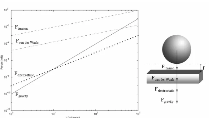
When components have submillimeter dimensions, their manipulation is technically embarrassed because of scale-effects which increase when the dimensions decrease. Indeed, the range of the micromanipulation is currently defined as the manipulation of objects whose volume is between 10 and 104 µm3 or who's the greatest dimension varies from some tens to some hundreds of µm. We are near the low limit of the classic mechanics. The laws of the Newtonian physics are most of the time valid and the quantic effects can be neglected. However, the main difference between microscopic and macroscopic scales is due to the change of dominant forces. Let us consider L as a length that is characteristic of a problem, the value of L3 being inferior to the one of L2 in the [0, 1] interval, the volume forces become negligible compared to the surface forces. Therefore, the forces relying on contact surface (electrostatic force, surface tension, van der waals force) become important in the microworld (see Fig. 1.4).
Moreover, precise determinations of the interaction force need deep studies crossing the model at the micro/nano-scale and the deformation of the surface. As in Fig.1.4, the forces are getting on for sphere/plan. Because of the mixture action of these forces, it leads to micromanipulation a big difficulty.
The scale effect arises many challenges, it requires new robotic functions, actuations, perceptions, handling and controls. These functions can not be directly transferred from the macroscale robotics and new principles of design have to be studied. The integration of these functions in a complete micromanipulation system and micro-assembly is also an ambition on which several proposals have been done but getting a station or a set of stations which are precise, repeatable, safe, efficient and flexible remain a challenge.
Fig. 1.4. The different forces in the microworld for a sphere/ plane interaction.
In this chapter, we first give some application fields. After that, we focus on the main components of microrobots: the structure, the actuators, the sensors and the control.
1.2 Application fields of microrobots
1.2.1 Microrobots in microfactories
The integration of microrobots inside microfactories which work as production systems is a challenge. This integration can be considered at different levels from the teleoperated station until the totally automated microproduction systems. The microfactory concept is the answer to the need of microrobotics systems integrated in automated stations.
An example of microfactory was developed by Mechanical Engineering laboratory (MEL). It is shown in Fig. 1.19. The entire system contains a micro-lathe, a micro-milling machine, a micro-press machine, a micro-transfer arm and a micro-manipulator. All the components are integrated into a portable box with 625 x 490 x 380 mm3 in sizes. This microfactory is controlled by two multi-DOFs joysticks and vision assistance.
Fig. 1.5. A microfactory by Mechanical Engineering Laboratory (MEL), Japan [MEL].
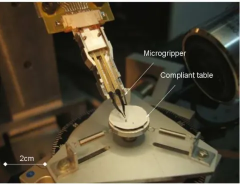
Femto-st has developed several stations dedicated to micromanipulation and microassembly. One of stations is composed of 5 high accuracy axis (3 linear axis and 2 rotational axis) carrying a microgripper. This microgripper was designed in Femto-st (old Laboratoire D'automatique Besançon) and patented in 2002. This robotic device is associated to a vision device, which is a motorized binocular microscope. An environmental control is ensured by dust filtration (class 100). Robot is controlled by two computers, one for operator inputs (joystick, keyboard) and the other for real-time video stream. Video is used by both operator and computer for manual control and computer vision control.
As well as technical demonstrator and experimental platform, this microassembly robotic system is used to experiment research work on microassembly.
Fig. 1.6 shows the large view of the micromanipulation/microassembly SAMMI platform. The robot is fixed on a vibration filtering table and protected by a laminar flow cabinet. Computers and joystick are visible on the right.
Fig. 1.7. Large view of assembly area.""""
A component placed on a compliant table with 400 µm in length is handled by microgripper visible on the center of Fig. 1.7. Two pieces with 100 µm are assembled in this station (see Fig. 1.8).
This kind of system based on microrobots aims to perform automatic control of micromanipulation and microassembly tasks. These tasks allow us to fabricate complex devices and products for industrial or consumption applications.
1.2.2 Microrobots in biology and medical applications
Another field of application for microrobotics is in the biology. In the biology field, cells have typical micrometer dimensions. Researchers in this field wish to manipulate biologic cells, including positioning, sorting, selecting and separating biological cells. These manipulations permit to study various behaviors of different cells. Furthermore, in the genetic engineering, they also require manipulations to decode the gene, or even improve the human gene.
Fig. 1.9. Microinjection of the cell [TMW].
These manipulations need high accuracy and precise tools enable to perform complex tasks on fragile objects, in changing environments (see Fig. 1.9).
In the medical field, Microrobots may be used to inspect, treat or eliminate medical problems. The use of microrobots can inspect inside of human body, and reduce the pain using traditional inspecting approach. Moreover, some problems may arise due to the accumulation of unwanted organic substances, which interfere with the normal body functions, such as tumors, life threatening blood clots, accumulation of scar tissue, arterial blockage, and localized sites of infection. The microrobots can be introduced into the body through the circulatory system.
One of the effective approaches to kill the cancerous cells would be to enclose the entire tumor in a nano box and destroying everything in the box. The prospective scene in Fig. 1.10 shows a microrobot going to take out the cancerous cell in the human body.
Fig. 1.10. Prospective view of microrobot in the human body [BMM].
1.3 Design of microrobots
Either for assembly or packaging of micro-objects including MEMS and MOEMS or the characterization of mechanical or biologic objects, specific microrobots have been designed. They are different from the traditional robots in the sense that their architecture, their actuation or their control are often different. We have seen that the main reason of this difference is the predominance of surface forces in the microworld. Microrobots have to feel their environment and their action on the objects they are touching. The sensing system has to be adapted to microscale, by which informations are given as the base for an automatic process.
The design of microrobots concerns the design of the carrier and the end-effector.
Concerning the design of the end-effectors which permit to handle and release the components, lot of works have been done in the world [LANG 08]. Indeed, because surface effects become predominant at microscale, the release of objects is difficult to perform and the study of necessary strategies is particularly interesting. Moreover, handling systems are often designed based on the use of smart materials that lead to control difficulties [LANG 08]. Concerning the carrier, usually, they are designed based on the miniaturization of mascroscopic concepts, and the size is centimetric or decimetric. The analyses of kinematics structure adapted to micromanipulation have been done most of the time for the handling system and not for the whole microrobotic structure.
Therefore, according to these considerations, we consider the design of microrobots through three main aspects:
- microrobot kinematics;
- adapted actuators for the microrobot kinematics; - control and perception.
1.4 Kinematics for microrobots
The kinematic chains of traditional robots are built by three components: actuators (electromagnetic motors), links (most frequently rigid bodies), and joints (kinematic pairs) to obtain the desired degrees of freedoms (DOFs). However, microrobots can not be built on the same approach because of the physical reasons described previously. Special kinematics for microrobots has to be designed.
Kinematics chains aim to build connections from energy input (actuators) to mechanical energy output (end-effectors) to create desired motions. Different approaches are developed to design kinematic chains of the microrobots such as the bimorph mechanism [CAR 98], the parallel mechanisms, the topology syntheses of mechanism [KOTA 01], etc.
Before talking about these various mechanisms, we firstly introduce different connection joints. The transmission of the rotation and translation motions is realized by the connection joints. There are many traditional joints, such as hinges, sliders and universal joints. However, in microrobotics, there is another type of joint called compliant joint. The researches already done show that the use of compliant joints presents many advantages in the microworld.
1.4.1 Compliant joints
The traditional joints use the sliding area to create motions. Unlike this kind of joints, the compliant joint uses deformation to create motions. The compliance of the structure is defined by the structure geometry.
Two kinds of compliant joint are mentioned: the revolute joints (see Fig. 1.11a) and the translational joints (see Fig. 1.11b).
(b)
Fig. 1.11. (a) rotation of joint (b) translational joints.
The compliance of the joint depends on geometry and dimensions. For example, rotation stiffness of the compliant joint (see Fig. 1.12) can be given by:
2 2
L EI k =
E is Young's modulus, I is the moment of inertia.
Fig. 1.12. Deformation of a compliant joint.
These compliant joints eliminate friction, backlash and wear. Further benefits include sub-micron accuracy due to their continuous monolithic construction. Such accuracy is important in many micro or nano-applications. The monolithic fabrication also enables a low-cost process. However, it presents some drawbacks such as the limited motion range, changing rotation centre, etc.
1.4.2 Bimorph mechanisms
The bimorph mechanism is a kind of mechanism widely used in microrobotics, as bimetal beam, bimorph actuator, etc. Generally, Bimorph mechanism consists of two active layers. The displacement can be created because of the asymmetric deformation via:
• Thermal activation (a temperature change causes one layer to expand more than the other).
• Electrical activation as in a piezoelectric bimorph (electric field(s) cause one layer to extend and the other layer to contract).
(a)
(b)
Fig. 1.13. (a) classic bimorph mechanism (b) a model of a bimorph mechanism.
As shown in Fig. 1.13b, the input displacement δi of spring leads to an output deflections δo. In fact, in the real situation, the pin connection is replaced by a compliant joint, and the elongation of spring is made by actuating active material or electrothermal expansion effect. Another example uses this principle (see Fig. 1.14). A PZT stack is used as the input end, the output ends are two fingers [CAR 98]. The input PZT gives the external beam (as spring) elongation, which leads to the internal beam deflection at the position A. So, the position B is led to a bigger deflection.
In fact, the use of the piezoelectric material, electro polymer bimorph, etc, can take the same principle to amplify the motion range. To sum up, the key of this amplification mechanism is to create the deformation difference between two materials.
Fig. 1.14. Example of bimorph principle [CAR 98].
1.4.3 Topology synthesis of compliant mechanisms
Compliant mechanism synthesis has been performed by large number of researches. This method includes two common tasks: (a) topology generation (b) size and shape optimization [KOTA 01].
Topology generation provides qualitative results of a kinematics. This mechanism may not be the best solution in the size and shape. Therefore, once the topology is generated, the next step is to perform a size and shape optimization.
The goal of this first stage in compliant mechanism design is to generate a topology (configuration) to meet defined input-output force-displacement relationship. There are two commonly used schemes for initial discretization in the topology synthesis: the use of homogenization method and the use of an initial beam/truss element network.
As can be seen from the flowchart in Figure 3, the proposed approach includes 3 major components:
• The embedded finite element analysis that solves the structural deformation.
• The curve comparison algorithm that measures the deviation between the deformed and target curves.
• The overall optimization problem that searches for the optimal topology and dimensions.
Fig. 1.15. Flowchart of compliant mechanism synthesis [KOTA 01].
Fig. 1.16 shows an example of amplification mechanism designed by compliant mechanism synthesis, which amplify the input motion 20 times.
This method is complex and requires special computer program to perform the design. But, it gives optimized solution to satisfy the requirement between input and output. The main developed program resolves the single input-output problem. Recently, some researches are done in developing algorithm to resolve multi-input and multi-output problem [GROS 08].
1.4.4 Parallel microrobots
Parallel robots have played an important role over the last 20 years wherever they were used in the macro or micro world. A parallel robot is a closed-loop mechanism in which the mobile platform is connected to the base by at least 2 serial kinematics chains.
(a)
(b) (c)
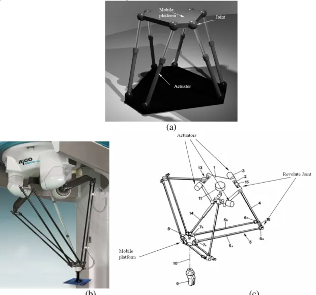
Fig. 1.17. (a) Steward platform (b) Delta robot (c) Schematic of the Delta robot (from US patent No. 4,976,582).
Typical parallel robots are Stewart platforms or Delta robots (see Fig. 1.17). The joints have rotation DOF as the passive connection which can support the platform and increase the stiffness of the whole structure.
This traditional robot requires accurate assembly of sensors, actuators and connection joints. Due to previously presented scale effects, traditional assembly can not be realized in the microworld. However, researches found that the use of monolithic structures fabricated by microfabrication technology present many advantages. Thanks to these techniques, the parallel microrobot with integrated actuators and the various parts can be fabricated. It is a potential candidate for microrobotics applications.
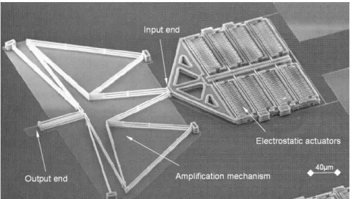
D. Mukhopadhyay [MUK 08] proposed a parallel mechanism (see Fig. 1.18). It is a planar xyθ positioner with linear electrostatic actuators.
(a)
(b)
This parallel mechanism consists of a platform connected to the base by three identical kinematic chains. Each chain consists of a prismatic joint connected to a fixed base on one end and to a rigid link on the other end via a compliant joint. This parallel mechanism can be open-loop controlled by identifying the Jacobian matrix. Since there is no any sensor, the repeatability and the accuracy can no be ensured.
The use of microfabrication technology permits to fabricate parallel microrobots with high resolutions, monolithic structure and micrometer dimensions. However, repeatability and accuracy can not be ensured because the sensors are not integrated.
1.5 Actuators for microrobotics
Microactuators are key components for MEMS or microrobots. Microactuators transform electrical energy, thermal energy, magnetic energy, etc. into mechanical energy.
Thanks to the efforts of researchers, various microactuation principles such as thermal expansion, magnetic actuation, electrostatic actuation, piezoelectric actuation and shape memory alloys have been developed. Many original, smart microactuators have been designed, fabricated and tested. In the next section, a brief review based on actuation principles is presented.
1.5.1 Electrothermal microactuators
Thermal expansion is the property of materials to change in volume in response to a change in temperature, where the change is approximately proportional to the material's coefficient of thermal expansion. The table gives the coefficient of linear thermal expansion of three types of materials: metal, semiconductor and insulator.
Tab. 1.1. Coefficient of linear thermal expansion of different materials.
Material Coefficient of linear thermal expansion (1/C)
Metal 13 to 25×10-6 Semiconductor 3 to 6×10⁻⁶ Silicon oxide 0.5×10 -6 Insulator Glass 8×10⁻⁶
As shown in the table 1.1, the linear expansion leads to very few changes in length and researchers have design various mechanisms to amplify this linear motion.
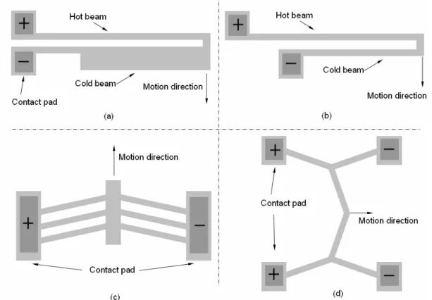
Fig. 1.19. Example of amplification of thermal actuators (a, b) U-shape, (c, d) V-shape, cascaded V-shape.
Fig. 1.19 shows the U and V shape thermal microactuators and their mutant shapes. The U-shape microactuator consists of two beams: a thin beam and a thick beam. Because of the asymmetric expansion in these two beams, transverse motion is obtained. The V-shape thermal microactuator consists of a curved beam. The symmetric expansion creates a flexion in the middle of the beam.
Since the asymmetric expansion results from Joule effect, this approach permits to build an actuator with a single layer (unique material). The temperature change can be achieved internally by electrical resistive heating (Joule heating) or externally by a heat source capable of transferring the heat to the actuator.
Fig. 1.20 presents a bi-metallic thermal actuator. In this configuration, both materials are heated to the same temperature, but deflection results from different coefficient of thermal expansion.
Fig. 1.20. Bi-material thermal microactuator.
The advantages of thermal microactuators are the fast heating (electro-thermal effect) and compatibility with microfabrication technology. The drawback is the reverse transformation. The cooling will reduce the response time of the actuator.
1.5.2 Electromagnetic microactuators
Ferromagnetic material (such as Ni, Fe, Co, NiFe, NdFeB) presents attractive effects when subjected to a magnetic field [GIB 04]. Ferromagnetism is the basic mechanism which is widely used for most phenomena of magnetism.
The ferromagnetic material can be soft magnetic material or hard material, while soft materials such as permalloy (FeNi) are relatively easy to prepare in film form by electrodeposition and sputtering.
Fig. 1.21. Electromagnetic force.
Although soft magnetic materials can be obtained easier than hard magnetic materials, hard magnetic or permanent magnetic materials would be more appropriate in some cases. For
example, hard magnetic materials with a high remanent magnetization can be conveniently used in bi-directional (push-pull) microactuators [CHO 00].
In order to make an electromagnetic microactuator, a ferromagnetic material and a coil are required (see Fig. 1.21). However, the fabrication of a microcoil is a hard task. This is why traditional electromagnetic motor are not widely used in the microworld.
L.K. Lagorce [LAG 99] designed an electromagnetic microactuator based on polymer magnets. The basic structure of the fabricated cantilever beam microactuator is illustrated in Fig. 1.22. A polymer magnet magnetized in thickness direction is screen-printed onto the free end of a copper cantilever beam. On the other side of the substrate, a planar square coil produces the magnetic field gradient necessary for the actuation of the magnet. Because Polymer magnet is a permanent magnet, the change of the electric current direction can result in a change of the deflection of the magnet.
Fig. 1.22. Electromagnetic microactuators based on polymer magnets [LAG 99].
Magnetostrictive materials are a type of material which deforms due to the applied magnetic
field; it has been firstly discovered by James Joule. Typical magnetostrictive material is known as Terfenol-D, including rare earth elements with iron which has the available strains of more than 1000 parts per million at room temperature with a relatively small applied fields [TDD] [ROT 92]. Fig. 1.23 shows the strain versus magnetic field (H) that presents saturation at high field.
The use of electromagnetic materials presents fast response time, great force, wireless actuation, bi-direction actuation (for hard magnetic materials), etc. However, the fabrication of coil limits their applications in the microworld [CHO 00] [OKA 09].
Fig. 1.23. Magnetic field Vs strain for a Terfenol-D material.
1.5.3 Electrostatic microactuators
Electrostatic charge can exert a force between the charged objects according to the Coulomb law [CL]. Although only a small force can be obtained, this could be useful in the microworld. The simplest type of electrostatic actuators consists of a movable plate which is pulled toward a parallel electrode under the application of a voltage difference. This type of actuator is illustrated in Fig. 1.24.
Fig. 1.24. Parallel plate electrostatic actuator.
The movable electrode is suspended by a mechanical spring, which is usually a simple microfabricated cantilever. When a voltage is applied across the electrodes, opposite charges on each plate attract each other. However, unless they touch, the electrodes only draw sufficient current to charge the actuator's effective capacitance, resulting in low power requirements.
The attractive force is given by: 2 2 2d SV Fe
ε
= S: aread: gap
ε : Permittivity
The spring force increases linearly with the gap between these two plates, but the electrostatic force increases faster while there is a small gap. So there is a maximal applied voltage, when we go though this voltage, these two plates will be contacted, this is called pull-in effect. The spring force is given by:
) (d0 d
k Fs = −
k: the spring constant d0: initial gap ∂ ∂ = ∂ ∂ = d F d F F F s g s g
Using these equilibrium conditions, the maximum applied voltage can be found:
S kd Vm
ε
27 8 03 =The gap is: 3
0
d d =
This gap is the maximum motion distance. If the motion is beyond this distance, these parallel-plate actuators suffer from instability for voltages beyond a threshold known as the "pull-in" voltage. For voltages beyond the pull-in voltage, the electrostatic force grows more quickly than the mechanical spring force, causing the two plates to contact each other.
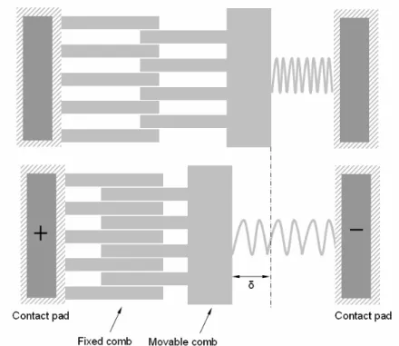
Hence, these actuators can not be stable operated for deflections larger than this unstable position. However, many types of mechanical springs, including fixed-fixed beams, exhibit nonlinear deflection characteristics, leading to a larger usable deflection range. To avoid the pull-in effect, Comb drive electrostatic microactuators are a good solution. As parallel-plate actuators, comb drives consist of one fixed and one movable electrode. The electrodes are shaped as interdigitated combs as shown in Fig. 1.25.
This configuration leads to a constant force over the whole range of deflection of the movable comb. As long as each comb finger is perfectly centered between two opposed comb fingers, the transverse force acting on that finger will be null.
The electrostatic actuator offers a very high efficiency actuation because of low current consumption, and the response time is very fast. They could be designed and fabricated easily
by micromachining technology. But, when the electric field must act over larger distances, a higher voltage will be required to maintain a given force.
Fig. 1.25. Principle of the comb drives electrostatic microactuator.
1.5.4 Piezoelectric microactuators
Piezoelectric actuators are the most widely used actuators as active material because of their high operating frequency range and power density.
Piezoelectric materials change their shapes under an electric field. This change can be described by defined directions. Since the polarization of piezoelectric materials leads to an anisotropy deformation, the direction of the piezoelectric material is defined as in Fig. 1.26.
Typical piezoelectric materials include quartz (SiO2), lead zirconate titanate (PZT), lithium niobate, and polymers (polyvinyledene fluoride (PVDF)). Fig. 1.27 shows the deformation of a piezoelectric material under different electric fields. The coefficients d15, d33, d31 represent the deformation ratio versus voltage in the different directions.
Fig. 1.27. The piezoelectric material under voltage. Tab. 1.2. The range of the coupling coefficients.
Coupling coefficients Materials
d31 (10-12 C/N) d33 (10-12 C/N) d15 (10-12 C/N)
PZT From -100 to-300 From 300 to 600 From 500 to 800
Quartz -2.3 -0.67 4.6
According to this table, the motion range of piezoelectric material is very small. The actuator is usually realized by building a piezoelectric stack or a piezoelectric unimorph or bimorph to amplify the motion range. Many devices, such as microgrippers, micropositionners and oscillators have been realized using this principle.
Unimorph piezoelectric structure is made by bonding a piezoelectric material with another material (usually metal). Unimorph structure results in out of plane displacement under voltage [see Fig. 1.28 a]. Two piezoelectric unimorph beams build a microgripper to manipulate microobjects.
(a)
(b)
Fig. 1.28 (a) Microgripper including two unimorphs (Y. Haddab of Femto-st institute) [Yas 04](b) Two DOF microgripper (J. Agnes of Femto-st, institute) [AGN 03].
Although most of piezoelectric microactuators are based on traditional machining, piezoelectric thick film integrated silicon substrate has received considerable attentions in recent years for potential applications in MicroElectroMechanical Systems (MEMS) devices [MURA 05] [AKA 04] [WANG 07]. These piezoelectric thick film are made by dispersing submicro-sized (100-300nm) PZT powder (APC 850) into PZT sol-gel precursor solution (Zr/Ti = 53/47). PZT films were patterned by photolithography with S1818 photoresist and wet etched in HF/HCl [HAI 09].
1.5.5 Shape memory alloys microactuators
Shape memory alloys (SMA) are materials that present the property to recover its initial shape after a deformation due to heating induced phase changing. The phase from martensite to austenite is induced by a thermal energy.
The principle of SMA is shown in Fig. 1.29. SMA material endures firstly an elastic deformation at temperature T. When it is heated to temperature T+ŁT, it turns back to original shape, and it keeps this form at temperature T. When SMA material is deformed plastically, the induced plastic deformation can not be reversed completely.
The transition from the martensite phase to the austenite phase is dependent on the temperature and stress. While martensite can be formed from austenite by rapidly cooling carbon-steel, this process is not reversible, so steel does not have shape memory properties.
Fig. 1.29. Principle of SMA.
Shape-memory alloys (SMAs) have a lot of desirable properties: high power to weight (or force to volume) ratio, thus the ability to recover large transformation stress and strain upon heating and cooling, pseudoelasticity (or superelasticity), high damping capacity, good chemical resistance and biocompatibility [OTS 99] [HUM 99].
Besides the traditional applications, thin film SMA has been recognized as a promising and high performance material in MEMS applications, since it can be patterned with standard lithography techniques and fabricated in batch process [KAL 97] [MAK 00a] [MAK 00b]. The main advantages of TiNi thin film include high power density, large displacement and actuation force, low operation voltage, etc [FU 04].
Ferromagnetic shape memory alloys
Ferromagnetic shape-memory alloys (FSMA or MSH) are materials that exhibit large changes in shape and size due to an applied magnetic field. The key factor behind this phenomenon is martensite transformation of the crystal lattice below a certain temperature. In fact, a FSMA is first a SMA but it presents more interesting property that different variants of martensite can be changed under magnetic fields.
In FSM materials, when a sample is exposed to an external magnetic field in the martensitic phase, the magnetic field tends to realign the magnetic moments along the field. The resulting deformation can be as large as 10 % [GAU 08a], [GAU 08b].
Fig. 1.30. Principle of FSMAs.
Therefore, the material is an attractive candidate for a new class of magnetic actuators or microactuators. Since then, various ferromagnetic shape memory alloys are investigated.
1.5.6 Electroactive Polymers microactuators
Electroactive polymers (EAPs) are polymers whose shape is modified under voltage (see Fig. 1.31). They present a large amount of deformation and sustaining large forces possibilities. Due to the similarities with biological tissues in terms of achievable stress and force, they are often called artificial muscles, and have the potential for application in the field of robotics, where large linear movements are often needed.
Fig. 1.31 Principle of electroacticve polymers [LMTS].
EAP can have several configurations, but are generally divided in two main classes: Dielectric EAPs and Ionic EAPs.
Dielectric EAPs: the actuation results from electrostatic forces between two electrodes which squeeze the polymer. This kind of EAP is actuated by large voltages (usually several thousand of volts), but very low electrical power consumption. Dielectric EAPs require no power to keep the actuator at a given position.
Ionic EAPs: the actuation results from the displacement of ions inside the polymer. Only a few volts are needed for actuation, but the ionic flow implies a higher electrical power needed for actuation, and energy is needed to keep the actuator at a given position. Examples of ionic EAPS are conductive polymers, ionic polymer-metal composites (IPMCs) [FUK 05] [SHA 98].
1.5.7 Summary on the actuators based on smart materials
Each of the previous microactuators offers advantages and drawbacks. There is no microactuator with perfect performance. Usually we should find the tradeoff between the power/mass ratio, machining, integration, etc. to choose a microactuator for a specific application.
We can classify these microactuations by three classes from the point of view of energy transformation. The first class is the transformation from magnetic to mechanic energy. The second one is the transformation from thermal to mechanic energy. The third one is the transformation from electric to mechanic energy.
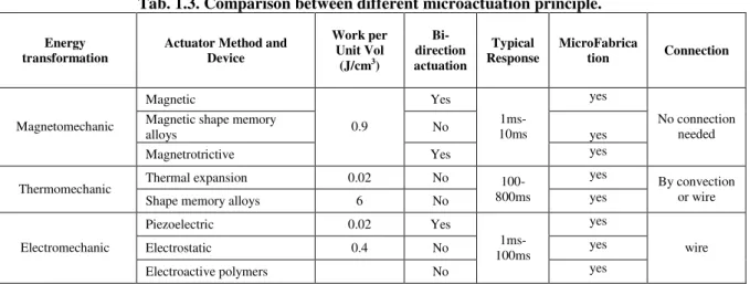
Table 1.3 summarizes the main characteristics between different principles of microactuators. The characteristics of the microactuation include work per unit volume, work per unit volume, typical response time, microfabrication process, connection approach.
Tab. 1.3. Comparison between different microactuation principle.
Energy
transformation Actuator Method and Device
Work per Unit Vol (J/cm3) Bi-direction actuation Typical
Response MicroFabrication Connection
Magnetic Yes yes
Magnetic shape memory
alloys No yes Magnetomechanic Magnetrotrictive 0.9 Yes 1ms-10ms yes No connection needed
Thermal expansion 0.02 No yes
Thermomechanic
Shape memory alloys 6 No
100-800ms yes
By convection or wire
Piezoelectric 0.02 Yes yes
Electrostatic 0.4 No yes Electromechanic Electroactive polymers No 1ms-100ms yes wire
1.5.8 Control of the microrobot
1.5.8.1 Control of the microactuator
Microactuators are designed based on these microactuation principles. They produce mechanical deformations by response of the energy input. The mechanical deformation presents intrinsic drawbacks. The typical intrinsic characteristics are [RAK 06a] [RAK 06b] [RAK 09a] [RAK 09b]:
• Hysteresis • Creep
• Plasticity • Relaxation • Fatigue
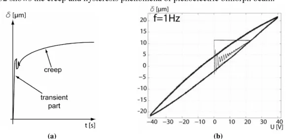
Fig. 1.32 shows the creep and hysteresis phenomena of piezoelectric bimorph beam.
(a) (b)
Fig. 1.32. (a) A creep phenomena of piezoelectric bimorph beam [RAK 09a]. (b) Hysteresis of a piezoelectric bimorph beam [RAK 09a].
These characteristics lead to unwanted behaviors when they are used in microactuator. It will reduce repeatability and accuracy. A precise mathematical model could be built to make a precise open-loop control. Otherwise, Closed-loop control techniques can be a solution to reach substantial performance (accuracy, repeatability, disturbances and vibration rejection.) [RAK 09a] [RAK 09b]. However, the integration of smaller sensor into a small actuator is also a hard problem.
Furthermore, the change of work conditions will result into the loss of high precision. There are a lot of factors which influence the control of microactuator such as the temperature, noises, and humidity [RAK 09a] [RAK 09b]. These uncertain factors increase hugely the difficulty to perform a precise control.
1.5.8.2 Microrobots controlled by proportional signals
As presented previously, the active material presents small deformations, For example, a piezoelectric ceramic of 1 mm in length produces a displacement of 1 µm under electric field [CHA 09]. The use of amplification mechanism can increase this displacement.
The final displacement of a single DOFs microrobot is controlled by amplitude of input signal, we call it proportional control. This kind of control can be used to control the bimorph mechanism, compliant mechanism, mechanism based on topology synthesis, and parallel mechanism, etc.
Fig. 1.33 presents an amplification mechanism which is designed by topology synthesis. This mechanism is built with an electrostatic actuators and an amplification mechanism. A voltage is applied to the electrostatic actuators, and the output tip moves. Their final position is maintained by the input voltage. It is possible to reach a high precision using calibration techniques. This single DOF mechanism can reach the desired position by a simple proportional signal.
Fig. 1.33. Single input-output mechanism [KOTA 01].
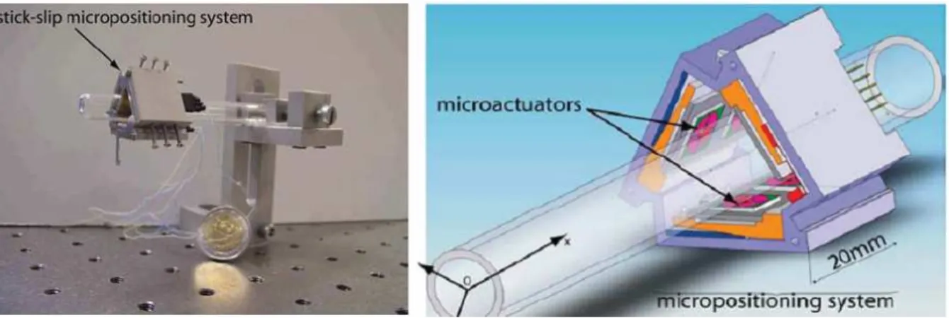
A parallel mechanism is designed by Q. Yao (see Fig. 1.34 and Fig. 1.35) [YAO 08]. It is a 3 DOFs parallel mechanism actuated by linear piezoelectric actuators. Three identical piezoelectric actuators are placed at a vertical angle (Z). This configuration permits to create a displacement in plane (X and Y) and out-of-plane (Z).
Fig. 1.35. The overall image of this mechanism [YAO 08].
The displacement can be defined by this formula;
= ∆ ∆ ∆
γ
β
α
35 34 33 32 31 25 24 23 22 21 15 14 13 12 11 a a a a a a a a a a a a a a a z y xaij: the Jacobian matrix (3 х N, and N is the number of bistable modules) abri; the relative angle.
This parallel mechanism can be controlled by proportional signal. Their final position is maintained by the input voltage on the actuators. Although this is assembled parallel mechanism with a centimeter dimensions, it presents high resolution because of high resolution of piezoelectric actuators.
However, as introduced in the last section, microactuators present many drawbacks [RAK 09a] [RAK 09b]: creep, plasticity, and hysterisis. These difficulties have to be resolved to reach desired performance. Some researches proposed some solutions of closed-loop control, such as robust control, state feedback control based on Kalman estimator [HAD 09].
![Fig. 1.38. Configuration of 2DOFs piezoelectric actuator, (a) Four used electrodes, (b) motion following O p x p , (c) Motion following O p y p [RAK 06a]](https://thumb-eu.123doks.com/thumbv2/123doknet/7705014.246282/54.892.249.646.183.537/configuration-piezoelectric-actuator-electrodes-motion-following-motion-following.webp)
