HAL Id: hal-01004924
https://hal.archives-ouvertes.fr/hal-01004924
Submitted on 22 Oct 2016HAL is a multi-disciplinary open access
archive for the deposit and dissemination of sci-entific research documents, whether they are pub-lished or not. The documents may come from teaching and research institutions in France or abroad, or from public or private research centers.
L’archive ouverte pluridisciplinaire HAL, est destinée au dépôt et à la diffusion de documents scientifiques de niveau recherche, publiés ou non, émanant des établissements d’enseignement et de recherche français ou étrangers, des laboratoires publics ou privés.
Distributed under a Creative Commons Attribution| 4.0 International License
A numerical procedure for regularized integral equations
for elastostatic problems of flat cracks in opening mode
Anh Le Van, Jean Royer
To cite this version:
Anh Le Van, Jean Royer. A numerical procedure for regularized integral equations for elastostatic problems of flat cracks in opening mode. Engineering Fracture Mechanics, Elsevier, 1991, 40 (2), pp.237 - 250. �10.1016/0013-7944(91)90260-8�. �hal-01004924�
E@nerring Frachue Mechank~ Vol. 40, No. 2, pp. 237-250.1991 eon-7944/91 s3.00 + 0.00
Printed in Great Britain. 0 1991 Pcrgamoa F’ra pk.
A NUMERICAL PROCEDURE FOR REGULARIZED
INTEGRAL EQUATIONS FOR ELASTOSTATIC PROBLEMS
OF FLAT CRACKS IN OPENING MODE
A. LE VAN and J. ROYER
Laboratoire de M&anique des Structures, Ecole Nationale Supcrieure de Mcanique, 1, rue de la Noi!, 44072 Nantes Cedex, France
Abdract-The regularid integral equations for flat cracks in opening mode are solved numerically by means of a simple procedure using new interpolation functions. The convergence and the accmncy of the method are tested on problems of circular and elliptical cracks embedded in the infinite medium, which admit analytical solutions. Computational results ensure the validity of this new approach. then they are compared with those already obtained without reguk&ation by the authors.
INTRODUCTION
FEW TIUDIMENSIONAL crack problems admit an analytical solution. Treated in the inWte medium case, they mainly concern cracks of particular geometries and subjected to particular loadings. The most well-known among these problems is that of the penny-shaped crack under an axisymmetrical pressure[l]. More recently, the case of more general loadings is fully studied in refs [2] and [3]. Like the penny-shaped crack, the elliptical crack also attracts many authors’ attention because of its particular geometry. The elliptical crack subjected to a uniform pressure is treated in ref. [4], whereas the case of a linear pressure is studied in ref. [4 and the case of a polynomial pressure in ref. [6]. For elliptical cracks subjected to shear loadings, the main contributions may be found in ref. [7] and more recently in refs [8] and [9]. The rectangular crack, though not very realistic, is another crack geometry amenable to analytical solutions[lO, 111.
For more general crack configurations, one often has to turn to numerical computations. Integral equations derived from the potential theory have the common feature of being singular in the sense of the principal value. The numerical treatment of the principal value is difhcult; a recent successful attempt to deal with this singularity in two dimensions can be found in ref. [12]. However, computations without l5articular treatment of the singular part are able to yield highly satisfactory results as shown in ref. [13].
The regularization task aims at lessening the principal value singularity, In theoretical respects, this yields weakly singular integral equations, which must be more tractable than principal value ones. In numerical aspects, the kernel of regularized equations is found to be lengthy and its discretization in the three-dimensional case remains for the time being inextricable. Recently, a numerical procedure based on the least squares global displacement gradient smoothing method was worked out in ref. [14] for flat cracks in opening mode.
The present paper describes a different approach to problems of flat cracks in opening mode, using new interpolation functions denoted by MC” and J The proposed numerical procedure has the advantage of being simple: similar to the non-regularixation method, the solution of the discretixed equation is carried out by the collocation method and the integration classically by Gaussian points.
DISCRETIZATION OF THE REGULARIZED INTEGRAL EQUATION
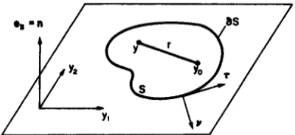
Consider a planar crack S embedded in the in6nite medium and subjected to an arbitrary internal pressure (Fig. 1). it is know!@ jl that under these conditions the opening mode is uncoupled from the other ones. The crack surface can be parametrized with Cartesian coordinates:
D = S 3 (yI , y2) -P y E S. The normal displacement discontinuity 4, = u: - u; is then related to P.FM 40/2-A
238 A. LE VAN and J. ROYER
Fig. 1. Planar crack. y,,: singular point; as: crack edge.
the third component of the stress vector with respect to the normal II of the crack by the following regularized integral equation [la:
(Implicit sums on Greek indices are made from 1 to 2.) Denoting by S, a neighbourhood of y, one can split up the surface integral in eq. (1) as follows:
v = r A II, r is the vector tangent to the crack edge 8s.
Let us introduce the following notations for the discretixation of eq. (2).
In a general way, the symbol ( ) relates to a row-vector, whereas ( } relates to a column-vector, and [] to a matrix.
The geometry transformation will be denoted: e. 3 t? +y E e, where e, is the reference element of the physical element e. The coordinates of point y are expressed in the usual way: Va E { 1,2}, y. = (iV(e)){y,}:, (N(t)) designates the shape function.
The Jacobian matrix of the geometry transformation is denoted by
WOI =
[
J&> = ~G,lD m.c, *)9
II
* .
its determinant by either detJ(t) or D(y)/D(<), and its inverse by
The last three integrals are quite regular and thus require no particular investigation. For instance if use is made of isoparametric elements, one has for any element e lying in S\S,,,:
It has been shown in ref. [16] that the first integral in eq. (2) is ordinary improper. So its study is less critical than that of a principal vahae integral integral. However, for numerical purposes an adequate integration scheme remains to be devised in order to take into account the weakly singular behaviour of the type r - *+r, 0 < y’ d 1. In this study, a numerical procedure will be proposed which makes it possible to solve this weak singularity.
Numerical procedure for elastostatic problems of fiat cracks 239
80
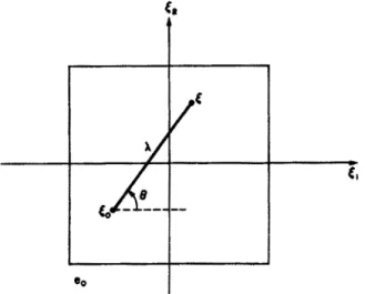
Fig. 2. Polar coordinatea (A, 0) in the nferenoc element e,. Case of a quadrilateral element.
First we define from (N(t)), [.I(<)] and b(r)], the following five functions which will be referred to as “mod&d”. The first of them was introduced in ref. [17J and widely used in I&S [14] and [18]. For each couple of points (<, &,) in e, we will consider the poiar ~~i~~ (A, (3) of 4, related to centre &, defined by (Fig. 2):
r,=&J,+acose & = C& + 1 sin 8.
The modified shape function (i?(&,, R, 0)) is such that:
wm -
<Wd) =
w%,
5 8))
W
and: lim (&(&,, A, 0)) < co.
(The notation A < 00 signifks that A is bounded
if
A is a real; that all ~rn~nen~ (resp. elements) of A are bounded if A is a vector (resp. a matrix)).The modified derivated shape functions (A@)(&,, 1, O)), a E (1, 2}, are such that:
and: lim (M(*)(&,, A, 6)) < co.
The modified Jacobian matrix [3(&,, A, O)] is such that:
[X)1 -
mill = 43tem
A ell
and:
lim[3go,
A,
e)] < Q).
The modified Jacobian determinant h(&,, A, 0) is such that:
and: lim &too, A,
e) < ~0.
det J(t) - det J(G) = AC!&&, 4, @)
The
modified inverse of the Jacobian matrix Lf(&,, A, t?)] is such that:w
WI
240 A. LFs VAN and J. ROYER
For simple elements, e.g. six-node triangles and eight-node quadrilaterals, the existence of functions (m) and (M(“)), a E { 1,2}, can easily be verified, and their expressions are also readily available. Concerning the other modified functions, the following proposition shows how to determine them:
Pl-OpOSltlOBl
If there exist (M@)(&,, 1,8)) a E (1,2}, then there also exist the functions [j(&,, rl, e)], d(&,, rl, a), u(&,, A,@] and they ark obtained by:
Va, B E {1,2), &9(&, A,@ = W%0, A, W{~P>~ #a)
&%,J, 0) = U2cr> +&&(r,) - &<r> -&J&) (4b)
where (y, S) is equal to (2,2) if (a, /I) = (1, l), to (1, 1) if (a, 8) = (2,2), and to (a, jl) otherwise. In the first or last two terms in eq. (4b), t: and to are interchangeable. Clearly, d # det .?. The foregoing proposition, which can easily be shown, enables us to obtain systematically the expressions for [s], a and [I], provided the existence of (M@)), a E { 1,2}. Expressions for the mod&d function (fi) can be found in ref. [18]i for the sake of completeness, we give them in the Appendix, together with the new functions (M@)) and [j]. Now we divide the neighbourhood S,,, of the singular point into elements e 3 yo, and transform the improper integral in eq. (2) over such an element as follows:
From eq. (3a): y, - y, = (W(0) - W(~o)))W = UWO, A, W{Y.zY
Furthermore, the difference in the kernel in eq. (5) can be transformed, using eqs (3b) and (3e):
A&) -L&o) =
~j^,,<ro,
1, 0
w
Lastly, by noting that: D({,, t2)/D(Iz, 0) = 1, the integral (5) can be rewritten hereafter where the square of polar radius A2 is now cancelled out:
This time the integration is to be carried over (A, f?) and eq. (7) involves only regular integrals which should yield no dBculties for the numerical purposes. It should be noticed that the common feature between the approaches in refs [14] and [18] and”the method herein propo&tf is ttiat regular integrals proceed merely from a numerical procedure. The kernel in eq. (5) actually remains (weakly) singular of the type r - 2+r, 0 < y I; 1. Here the.use of the interpolation type functions has made it possible to force the kernel to behave as a regular function in eq. (7).
Numerical procedure for elastodatk problems of flat cracks 241
Fig. 3. Change of variables square [- 1, + I]* 3 t, = (u,, 4) -+ (A, 0) 6 subtriangle in Q,.
In the following study, the discretixation of eq. (5) is carried out considering only two usual elements: the six-node triande and the eight-node quadrilateral. Nevertheless, the principle remains the same for any more general element.
Use of eight-node quadrilaterals
The integration over (A, 13) in the reference element e, is effected by dividing this element
into subtriangles and by making another change of variables in each of these subtriangles. This operation will allow us to bring again the integration domain onto the square [ - 1, + 11’ (Fig. 3). According to whether the antecedent I& of pointy, is located at a comer or on a side of element e,, the subtriangle number is 2 or 3.
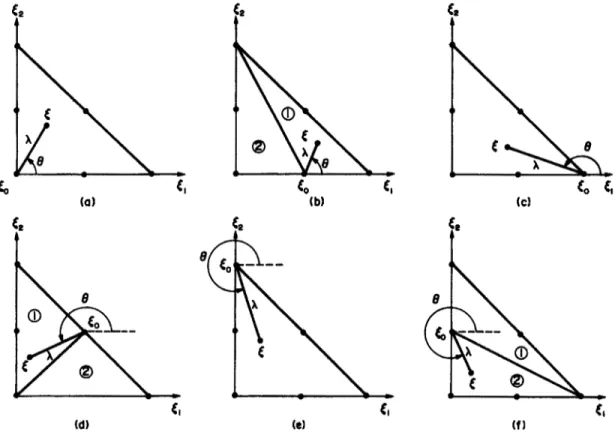
Case when to is located at a corner of element eo:
Let point to be located at node i E { 1,3,5,7} of element e. (Fig. 4). There are two subtriangles and it can be checked for the expressions of the polar coordinates (A,@ and the Jacobian of the transformation (u,, z+) --) (n,(I):
Subtriangles of type 1: Subtriangles of type 2:
1 = 1 +vi cos ( > i(l + 01) A = 1 +v, cos ( > i(l - 02) 8 =
s
(v2 + 2i - 1)8 = i (t+ +
2i + 1)o(n,=
IID(n,=
ItD(o)
8~0s D(a) cau of to at ncdr I hcase of&at node3 cast af&at nod85 caseaf~atnod87
242 A. LB VAN and J. ROVER
cam alEoat node2 case of&at na8e4 case of toat node6 cow oftoat node 6 Fig. 5. &, located at a mid-side of a quadrilateral element.
Case when I& is located at a mid-side of e,:
The four possible subcases are shown in Fig. 5. The node number of to is i E {2,4,6,8}. Here there are three subtriangles. By putting 0, = tan-l(2), the following relations can easily be established:
Subtriangles of type 1: Subtriangles of type 2:
o(n,=
x - 2e, D(v) 2 a((; - t?o)v~) Subtriangles of type 3: 1 =2ws(~:‘v~9 e+*-l)+ ;+1 (’ > ; me)= D(v) 4*s($l -v,)).Use of six-node triangles
Here use is made of the same technique of dividing element e, into subtriangles and making the change of variables [ - 1, + 112 3 v = (v,, vl) + (A, 6). If co is at a comer (resp. at a mid-side) of e,, the number of subtriangles is 1 (resp. 2). For triangular elements, there is no general rule and the six possible cases are to be considered separately. We recall the notation 0, = tan-‘(2). Case of to at node 1 (Fig. 6a)
1 _
l/%1+
4)
4cos7
8 ++ 1)
o(n,= .Jz
Nuxncrid procedure fat hatoatatk prablffas of flat cracks 243
(a)
0 L
G C
(cl) w
Fig. 6. Positions of to io a six-node triangle. Deihition of 2 and 8.
Case of &, at node 2 (Fig. 6b)
in subtriangle 1 in subtrthngle 2
il = 1 +v, A = 1 +v,
4 cos(a - 8)
8 = f<% - e&l + 2.Q 8 a- *,
2( u2- l)+n
244 A. LE VAN pad J. ROYER
Case of c,, at node 4 (Fig. 6d)
in subtriangle 1 in mbtriangle2
1 = 1 +v, A = 1 +v,
4cosy 4cosT
0 = 2 (02 + 4)
e = f (~2 +
6)Case of &, at node 5 (Fig. 6e) A.= 1 +v, 2cos ( > ;(l +vz) 8 ++ 13)
me)=
RD(v)
16 coso(n,=
x-00
D(v)
Discretized regularized equation
Eventually, the integral in eq. (5) assumes the following form:
84,
*(y)-%(yo)
ay, II
The integration over the variables (v,, v2) is made in the v-squares [- 1, + l]*. Since the kernels involved are regular, the Gaussian scheme for numerical integrations is quite acceptable. Rgure 7 presents the successive steps to pass from the former square.[ - 1, + 112 3 (v,, q) to the final physical element in which the point y = (yl, y2) lies.
Numerical procedure for elastostatic problems of tlat cracks
Fig. 7. Change from (u,, u2) to (y,, yz). Case when the element is a quadrilateral and ya lies at a comer of element e.
246 A. LE VAN and J. ROYER
Equation (8) together with eq. (2) constitutes the discretized regularized equation for a flat crack in opening mode. As remarked above, the weak singularity in eq. (2) has been removed with the aid of functions fi, Mea) and J ; of the numerical scheme there remains only <regular integrals.
NUMRRICAL PARTS Convergence test: the circular crack problem
Consider the problem of a circular crack centred at 0, with radius a, imbedded in the infinite medium and subjected to a uniform internal pressure p.
Like any flat crack in the infinite medium, the opening mode is uncoupled from the other modes. Four crack mesh configurations are chosen, containing respectively 85, 161, 209 and 321 interior nodes; the first and the last of them are presented in Fig. 8. Use is made of both six-node triangular and eight-node quadrilateral elements; those adjacent to the crack edge are quarter-point elements[l9,20]. All elements have straight edges; apart from the comer and quarter-point nodes the others are located at the mid-side of the edges.
For elements not containing the collocation point (i.e. lying in S\S,, see notations in eq. (2)), the integration is performed with 7 points over triangles and 9 points over quadrilaterals. Integration over elements containing the collocation point must be carried out using the change of variables which leads to a square integration region in the plane (a,, Q) (Fig. 7). The Gaussian quadrature scheme requires 3 x 3 = 9 points. Here the number of Gaussian points is twice as high as that used in the same study without regularization[l3]. This is accounted for by the fact that the original physical element is more “distorted” through the transformation (see Fig. 7) leading to the square element in the v-plane.
As expected, the numerical results show a revolution symmetry for the values of the displacement discontinuity & (Fig. 8). It should be noticed that the Young modulus E datum is unnecessary for computing the stress intensity factor K,. On the contrary, the Poisson ratio v must be specified; here it is set to be equal to 0.3.
Table 1 shows minimal and maximal errors on the displacement discontinuity & as well as errors on the stress intensity factor K,, with respect to the well-known analytical solution[l]:
E&(P)
=pJ[l -(p/a)*], p = 10~1;
8x(1 - v*) x2 which yields: Ki = 2pfi.
As remarked in the study of notched strips in ref.[l9], although the stiffness of quarter-point elements is reasonably accurate, the local values of stress and displacement in these elements are poor, thus our error estimations on & do not take into account quarter-point node values. Furthermore, the &-error is not maximal at the crack centre but at some radial distance varying according to the mesh configuration; in present cases it remains about 5% in magnitude. As regards tie &error, it markedly decreases as the mesh becomes denser. On the strength of these results, another investigation concerning an elliptical crack is treated in the next part.
Elliptical cracks
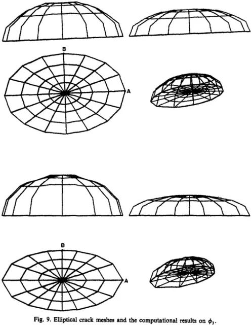
Consider an elliptical crack of semi-axes a, b, imbedded in the infinite medium and subjected to a uniform internal pressure p. Figure 9 shows the meshes for two cracks with semi-axes ratio a/b respectively equal to 1.5 and 2; they include 161 (resp. 113) interior nodes and 64 (resp. 48) elements. Here use is also made of quarter-point elements along the crack edge.
Table 1. Circular crack. Errors on ds and 4, with respect to the , analytical solution
NUUlbCt Mipimal errors Maximal errors ElT0l-S
of d.o.f. -4, on 4, on K,
85 0.28% 5.12% 6.06%
161 -0.05% 3.05% 2.29%
209 0.42% -4.41% 0.78%
Numerical procedure for elastostatic problems of flat cracks
A
Fig. 9. Elliptical crack meshes and the computational results on (B3.
The mesh generation technique is rudimentary: the crack is divided up with elliptical curves shaped in the crack contour, and radial straight lines issued from the crack centre. This inevitably gives rise to some distorted (elongated) elements which behave badly in numerical purposes. Moreover, this does not allow an accurate representation of the crack edge, whenever the semi-axes ratio becomes large. Figure 9 clearly shows that the mesh is particularly ill-suited to shape the vertex of the major axis. These reasons explain why computations are limited to small semi-axes ratio geometries. They also justify the use of 12 (resp. 16) Gaussian points on triangles (resp. quadrilaterals). Numerical results will be compared with the theoretical solutions [4]:
W31Y
1
8x(1 - v2) = pb 2xE(k) Jt1 - (VW2 - (Y2m21 where E(k) = j&i - k2
second kind.
sin2 rp] dv, k2 = 1 - b2/a2, denotes the complete elliptic integral of the
WA) = Kti =p+%WW) KI W = GIli. =P,/W21WW.
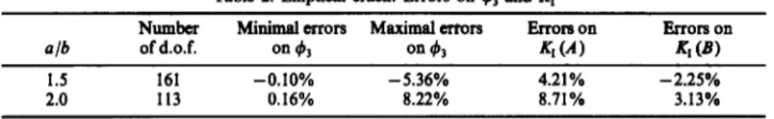
Table 2 gives minimal and maximal errors on the displacement ~~on~~ty & together with errors on the stress intensity factor K, at the vertices A, B of the semi-axes (Fig. 9).
248 A. LE VAN and J. ROYER
clb
1.5 2.0
Table 2. Elliptical crack. Errors on 4, and KI
NUXllber Minimal errors Maximal errors Rrrora on &rot3 on of d.o.f. on 93 0114, K,(A) RI (B)
161 -0.10% - 5.36% 4.21% -2.25% 113 0.16% 8.22% 8.71% 3.13%
As predicted, the values of the stress intensity factor at vertex B are always worse than those at vertex A, since the mesh is not smooth enough at 3, especially in the second mesh. The maximal &-error in the last mesh occurs at a point of the major axis, close to vertex B; it undoubtedly contributes to the large error on &(A). In order to improve the results, more sophisticated mesh
configurations must be devised, which result in an adequate refinement at the crack front and at the same time less elements at the crack centre where there is a small displacement gradient.
CLOSURE
The results show that the regularization method allows a high convergence and is quite operational for plane crack problems. Nevertheless, when computing rectangular cracks, for
unknown reasons the results obtained by the authors are too poor to be published here. For circular cracks, the errors on K, are quickly reduced to less than 1%. For elliptical cracks, despite a coarse mesh and a bad crack contour representation, &-values remain quite acceptable where they are larger. Obviously, the circular mesh type (with radial rays) leads to too many elements at the crack centre without enough elements along the crack front. Thus more sophisticated mesh generation techniques are required to obtain better results.
Moreover, compared to the classical transformation (c,, &) + (y,, y2), the transformation (tr,, oz)-Q,, yz) entails a greater distortion of the physical element and implies a denser integration scheme as a compensation. The Gaussian point number used here is twice or four times as high as that for the method without regularization (9 or 16 points instead of 4). The above distortion may also account for the faet that the elements seem to be very sensitive to their aspect ratio (ratio of their longer to shorter side): the longer elements are, the worse the results. In connection with the non-regularization method, there appear two questions which call for answers.
Can one avoid using quarter-point elements? Indeed, the use of quarter-point elements con- demned us to the range of six-node triangles and eight-node quadrilaterals. The non-regularization method, as shown in ref.[l3], gave good results without using special elements.
The regularized eq. (8) was obtained and used in Cartesian coordinates. Is it possible to obtain a regularized equation in other coordinate systems? With reference to the discretized equation for the non-regularization method, it enabled us to cope with more general coordinates and in particular to compute the stress intensity factor on a local basis.
Under present conditions, the results obtained with regularization are encouraging and should encourage investigations with an improved mesh generation technique, and in a further stage to numerical developments with the view to studying three-dimensional cracks.
REFERENCES
I. N. Sncddon, The distribution of stress in the ncighbourhood of a crack in an elastic solid. Proc. J& Sot. Lmdon.
Series R 187, 229-260 (1946).
J. T. Guidera and R. W. Lardner, Penny-shaped cracks. .I. Elasticity 5, ,59-73 (1975). J. C. Bell, Strews from arbitrary loads on a circular crack. Jnr. J. Fracfure 15, 85-104 (1979).
A. E. Green and I. N. Sneddon, The distribution of stress in the neighbourhood of a flat crack in an elastic solid. Proc. Comb. Phil. SW. Math. Phys. Sci. 46, 159-163 (1950).
M. K. Ka& and 0. C. Sih, Geometric discontinuities in elastostatics. J. Moth. Me& 16, 927-948 (1967). R. C. Shah and A. S. Kobayashi, Stress intensity factor for an elliptical crack under arbitrary normal loading. Engns Fracrure Mech. 3, 71-96 (1971).
M. K. Kassir and G. C. Sib, Three-dimensional stress distribution around an elliptical crack under arbitrary loading. J. appl. Mech. 601-611 (1966).
F. W. Smith and D. R. Sorensen, The elliptical crack subjected to non uniform shear loading. J. appl. Mech., Series
E 41, 502-506 (1974).
A. N. Rorodachev, Elliptical xxsck under the action of shearing streams of polynomial form. Prikl. M&I. 18,84-87 (1983).
Numerical procedure for elastostatic problems of flat cracks 249 [IO] M. K. I&sir, Stress intensity factor for three-dimensional m&ang&r Cracks. J. appl. Mech. 4& 308-312 (1881). [Ill M. K. Kasir, Three-dimensional rectangular cracks subjected to shear loading. fnt. J. Soli& Street. 18, 1075-1082 1121 ‘:?%ek and J. Sladek, The calculation of singular integrals in the boundary integral formulation of 2D elastostatics.
Fngng &al. 3,25-35 (1986).
[13] A. L.e van and B. &seux, Boundary element analysis of an inte8ral equation for threbdhnmsional crack problems. Znt. J. nwner. Mefh. Ensng 26, 2383-2402 (1988).
[14] E. 2. Polch, T. A. Cruse and C. J. Huang, Traction B.I.E. solutions for flat cracks. Cornput. Mech. 2,253-267 (1987). [15] H. D. Bui, Applications des potentiels &stiques B l%tude des flssures planes de forme arbitraire en milieu
colonel. Cwnpres Rend. Acad. Sci., Paris, t.288, Series A, 1157-1160 (1975).
[16] A. Levan and J. Royer, Theoretical basis of regularized integral equations for elastostatic crack problems. 8% J. Fracture 44, 155-166 (1990).
[17J F. J. Rizxo and D. J. Shippy, An advanced BIEM for three-dimensional thermoelasticity. Znt. J. moner. Mefh. Engng
11, 17521768 (1977).
1181 M. Bonnet, M&ode des equations integrales r$ulari&es en ~~~~que. Z%esis. Ecole Nationale des Pants et Chaussiies (November 1986).
[19] R. D. Henshell and K. G. Shaw, Crack tip elements are unnecessary. Int. J. numer. Mefh. Ettgng 9,495-509 (1975). [20] R. S. Bamoum, On the use of isoparametric tinite elements in linear fracture mechanics. Inf. J. numer. Mefh. &gng
10, 25-38 (1976).
APPENDIX
For the six-node trian8k and the eight-node quadrilateral, we give functions (N) together with the modified ftm&ms (#>, (M@> and [I). Function [_$I can be obtained from relations (4).
Six-node triangular elemenfs
Table 1A. Function N
: 4t’C, -C’(l - 2C’) 3 -Cr(l - 2 C,) ‘: 4ti& -G (l-2&) 6 Y’tz where<‘=l-t,-t,. Tabfe 2A. Function N
lo,(&l* 1* 6) 1
:’ 4(&cos (l-~~)(co~6+sin8)~2l(cosB+sin8)~ 8 - (O,(cos 6 + sin 6)) - 4L cos B(cos B + sin 6) (4&* - 1)cos 6 + w cos* e
4 4(& cos 6 + 6, sin 6) + 41 cos fJ sin 6 5 (4& - 1)sin 6 + 2L sin* 6
6 4([; sin 0 - &&cos 9 + sin 6)) - 4A sin B(cos 6 + sin 6) where <& = 1 - <,,, - &.
By noting that: 8,’ - 5;, = -X(cos 6 + sin 8), we obtain Table 3A. Table 3A. Function MU
1 qcose +sine) 4(cose +sinf!) 2 -4(2 cos 6 + sin 6) -4c0se
: 4cos6 0
4sine 4mse
: 0 4sin8
-4sine -4k0se +2sine)
Here the Iw(@ are independent of 1.
The modi@ed Jacobian inverse /
Application of relations (4) &es, after performing all calculations:
UG, 1, @)I =
1
A, A-, --f -1250 A. LE VAN and J. ROYER
where for any triplet (r, S, t) E {u, b, c, d, e, f, g, h,p, q)‘:
& = (ae - bd)[-r&CO, cos 0 + s(sin 8 t1, - 2&&* cos e - II& cos e) - t(2&, + 1 cos B)cos e]
+ (bp -ge)[+Os e 46 - 2to,tm sin e - ~t;~, sin e) - semtl sin e - t(x, + 1 sin ebb ei + (0~ - gd)[- rC,&, sin 0 - ~~~~~~ cos e - r(t,, sin e + Cm ~0s e + 1 sin 8 00s eji +(~+ce-_f-hd)[s(-~ozcose+~,,sine)-tcosel +(bq+cp-gf-Ire)[r(C,cose-&sine)-the1 +(cq -hf)[r c0se +S sine] with: a =4(d -2Y:+Y:) d=qy:-2y:+y3 b =qYt-Y:+Y:-Yf) e=*Y:-YZ+Y:-Y63 c = -3y;+4y:-3y: f= -3y;+4y;-3y;
g -4(yt +v:-2y9 P=4(Y:+Y:-2Y9
h = -3y;-y:+4y: q = -3y;-y:+4y;. Eight-t&e quadrilaterals
Table 4A. Function N
1 -(l - &I(1 - e,>u + tl + (2)
2 (1 -ml - (2)
3 -(l + <,I(1 -MU - <I+ 52)
4 (1 + CN - t:>
5 -(l + &)(l + C2N -cl - 52)
6 (1 - c:)u + &)
7 -(l - &)(l + e2)(1 + c, - C2)
8 (1 - &I(1 - r:,
Table 5A. Function A
1 { --co8 eta, + b,)a, - sin e(a, + b,)a, + A[a2 ~05~ e + (u, + a2 + b,)cos e sin e + U, sin2 e] - A2 COB 8 ain e(c0s e + sin e)}
2 b-da, -~3)~se-a,u3sine+l[(a3-a,)~sesine-o2C0s*e]+A2~s2eQiIlZe}
3 obtained from N,, iv2 by changing: (a,. a& a,) into ta?,a3, a,)
4 6, into b2
(cos e, sin e) ilitc (sin 8, -ai e)
5 obtained from N,, 8, by changing: (u,, 02.4) into @3,a4* a,)
6 b, into b,
7 obtained from fi,, fi2 by changing:
(c0s 8, sin e) into (-co8 8, -sine) (a,, q,o3) imJ (a,, a,. az)
8 b, into b4
(c0s 8, sin e) into (-sin 8, co8 0) where:
11, = 1 - co, b, = - 1 - cl, - h.7 4 = 1 - to2 b2 = - 1+ i’o, - tm
a3 = 1 + &, b3 = - I+ t + CM u4=1+& b4 = - I- c’o, + toz
Table 6A. Function Mu)
w)~, 4 0)
1 [(I - &I(2 ~0s e + sin e) - sin e(ze, + &)I [(I - G, )(2 sin e + ~08 e) - ~08 e(2cr2 + t,)]
2 to, sin e - cos e(i - c2) cos eg,, + 1~08 e/2)
3 [(i - to2)(2 cos 8 - sin e) - sin e(zt, - {,)I [(l+Co,)(2sine-cose)+co~e(2t2-t,li
4 -inO(&+ainO/2)
5 [(l + &)(2 ~08 8 + sin e) + sin e(2C, + r,) -(co?~se +tiw~+c,)) 6
7 -(mine+=eU,+C,)) .
~-g,)(cose+2=e)+=3seeQ+c,)
~~~)(2c0se-sme)+s3ne(2c,-c2) [(l - &,)(2 sin e - cos e) - ~08 e (2(, - 4,)
8 tacOse -sine(l -{,I
![Fig. 3. Change of variables square [- 1, + I]* 3 t, = (u,, 4) -+ (A, 0) 6 subtriangle in Q,](https://thumb-eu.123doks.com/thumbv2/123doknet/8092023.271438/6.763.143.627.76.266/fig-change-of-variables-square-i-a-subtriangle.webp)

![Table 1 shows minimal and maximal errors on the displacement discontinuity & as well as errors on the stress intensity factor K,, with respect to the well-known analytical solution[l]:](https://thumb-eu.123doks.com/thumbv2/123doknet/8092023.271438/11.756.197.553.948.1055/minimal-maximal-displacement-discontinuity-intensity-respect-analytical-solution.webp)