HAL Id: hal-01222683
https://hal.archives-ouvertes.fr/hal-01222683
Submitted on 30 Oct 2015
HAL is a multi-disciplinary open access
archive for the deposit and dissemination of
sci-entific research documents, whether they are
pub-lished or not. The documents may come from
teaching and research institutions in France or
abroad, or from public or private research centers.
L’archive ouverte pluridisciplinaire HAL, est
destinée au dépôt et à la diffusion de documents
scientifiques de niveau recherche, publiés ou non,
émanant des établissements d’enseignement et de
recherche français ou étrangers, des laboratoires
publics ou privés.
Smart retina as a contour-based visual interface
Paul Nadrag, Antoine Manzanera, Nicolas Burrus
To cite this version:
Paul Nadrag, Antoine Manzanera, Nicolas Burrus. Smart retina as a contour-based visual interface.
Distributed Smart Cameras Workshop (DSC’06), Oct 2006, Boulder, United States. �10.1.1.146.4893�.
�hal-01222683�
Smart retina as a contour-based visual interface
Paul Nadrag
Politehnica University Bucharest - ROMANIA[email protected]
Antoine Manzanera
ENSTA - LEI Paris - FRANCE[email protected]
Nicolas Burrus
ENSTA - LEI Paris - FRANCE[email protected]
Abstract
The purpose of this work is to provide a robust vision-based input device. In our system, a programmable retina is looking at the user who sends commands by moving his hand. The fusion between the acquisition and the processing functions of the retina allows a close adaptation to the light-ing conditions and to the dynamic range of the scene. Thanks to its optical input and massive parallelism, the retina com-putes efficiently the contours of the moving objects. This feature has nice properties in terms of motion detection capa-bilities and allows a dramatic reduction in the volume of data to be output of the retina. An external low-power processor then performs global computations on the output data, such as extreme points or geometric moments, which are tempo-rally filtered to generate a command.
1 Introduction
A vision-based interface is a system allowing to send symbolic commands to a computer just as a mouse or a key-board does, but with visual interaction only. Using a camera as an input device is an attractive issue for numerous appli-cations, from disabled persons assistance to intelligent home environments. To be really useful, such systems must not be invasive at all: it must neither impose to the user the wearing of any equipment, nor induce any constraint in the decora-tion of the scene observed by the camera. But detecting or recognizing the visual features independently of the scene content and its variation is a difficult task.
We are using in this work a vision system composed of a smart camera (programmable retina) and an external low-power processor (ARM). The interest of this approach is twofold:
1. The intimate combination of acquisition and processing functions of the retina allows to maintain a high fitness between the scene lighting properties and the further processing: in our case, the acquisition is adapted ac-cording to a local contrast criterion, in order to enhance the stability of the contours, which are the visual fea-tures chosen to detect the interaction.
2. The massive data reduction which is made between the optical input of the retina and the contour descriptor ma-nipulated by the external processor is in perfect adequa-tion with the I/O flow of the visual interface: image in, symbol out. By minimizing data transfers thanks to the massive parallelism and to the global measure output,
the system is designed to optimize this flow from an en-ergetic point of view.
Section 2 presents the Programmable retina within the vision system, its instruction set, acquisition and program-ming paradigms. Section 3 deals with image processing al-gorithms: the moving contour detection is detailed, and its properties are discussed. In Section 4, the higher level pro-cessing is presented and our first experiments in a drawing interface application are exposed. Finally, Section 5 out-lines the contributions and presents some perspectives of this work.
2 Programmable retina
The programmable retina concept originates from the NCP (Neighborhood Combinatorial Processing) retinas [12], which were SIMD Boolean machines. The NSIP (Near Sensor Image Processing) concept [7] then allowed to pro-cess graylevel images. Now, the highly submicronic level of CMOS technology allows to put more and more power-ful processing circuitry aside the photoreceptors while pre-serving good acquisition performance and resolution. The most recent circuit that has been fabricated and validated is a 200 × 200 retina called Pvlsar 34, with an elementary digital processor and 48 bits of memory within every pixel.
The algorithm presented in this paper was implemented on the architecture presented in Figure 1). The retina
Pvl-sar 34 is both a CMOS sensor and a parallel machine. It
is a grid of 200 × 200 pixels/processors connected by a reg-ular 4-connected rectangreg-ular mesh. The processors operate synchronously, on their local data, a sequence of instructions being sent by the controller, which is the NIOS processor IP core of an Excalibur FPGA chip. The host processor or cor-tex is the ARM processor hardware core of the Excalibur. It can exchange data with the retina, modify the program sent by the NIOS to the retina, and is in charge of the higher levels of computation (i.e. non-image processing).
Every pixel/processor p of the grid G is composed of:
• one photoreceptor,
• one Analog to Digital Converter,
• 48 bits of digital memory {pi}, 1 ≤ i ≤ 48.
• one Boolean Unit (BU), which can read some bits of the
digital memory, compute a Boolean operation and write its output on one bit of the digital memory.
000000000000000 000000000000000 000000000000000 000000000000000 000000000000000 000000000000000 000000000000000 000000000000000 000000000000000 000000000000000 000000000000000 000000000000000 000000000000000 000000000000000 000000000000000 000000000000000 000000000000000 000000000000000 000000000000000 000000000000000 000000000000000 000000000000000 000000000000000 000000000000000 000000000000000 000000000000000 111111111111111 111111111111111 111111111111111 111111111111111 111111111111111 111111111111111 111111111111111 111111111111111 111111111111111 111111111111111 111111111111111 111111111111111 111111111111111 111111111111111 111111111111111 111111111111111 111111111111111 111111111111111 111111111111111 111111111111111 111111111111111 111111111111111 111111111111111 111111111111111 111111111111111 111111111111111 0 0 0 0 0 1 1 1 1 1 processing High level PAR code BU A / D CONTROLLER HOST PROCESSOR CORTEX Analog sum Data Program Optical input Modify Code 1 PIXEL/PROCESSOR Phoreceptor
Boolean Unit Digital memory
Retina
Analog/Digital Conversion
Figure 1. Architecture of the system composed of a retina and a cortex, with focus on one elementary processor.
For a given memory index i, the set Xi =
[
p∈G
pi is a
200 × 200 binary image called “bit plane”. The elementary operations of the retina are massively parallel instructions of the form Y = OP(X1, X2), where X1, X2,Y are 3 bit planes (not necessarily distinct) of the digital memory, and OP is any binary Boolean function (e.g. AND, XOR, AND NOT, etc). Every pixel of the retina shares 1 bit of its memory with each one of its 4 closest neighbours. This enables spatial interactions and image translations.
Regarding data extraction, there are two ways to output information from the retina:
• by transfering sequentially (translating) the image, to
get the exact content of one or more bit planes of the digital memory.
• by using the Analog Global Summer, which provides in
constant time an approximate measure of the number of 1s in any bit plane of the digital memory.
Although simple, this last feature is important as it pro-vides efficiently global measures that are very useful to get spatial statistics or to detect the convergence of relaxation algorithms.
The Analog to Digital Conversion is performed during the acquisition, and is a plain part of the retinal program. In-deed, the acquisition of a n graylevels image is done by mul-tiple readings of the photoreceptor which provide (n − 1) bi-nary images (level sets) along the time (Figure 2). The pho-toreceptor (photodiode) is loaded to tension Vmax and then
unloads linearly with time, with a slope proportional to the amount of photons received. The graylevel is then computed in every pixel by counting (on log2(n) bits), the number of times the tension at the bounds of the photodiode is below a threshold tension Vs. Thus, an acquisition is defined by the
set of time indices {xi}i=0..n−1, corresponding to the reading
instants of the photodiode.
The acquisition and digital coding of a n graylevels im-age is performed in n + log(n) operations, corresponding to the sequence of Boolean operations performed to add the (n−1) level sets. Of course, the resulting digital image
occu-Vs V
t
Figure 2. Graylevel acquisition by multiple reading of the photodiode.
pies log(n) bits of memory in every pixel. Then, the retinal program applies a sequence of arithmetic and logic opera-tions that are completely written in software, at the bit level. However, if the number of operations (and thus the energy consumption), is not critical, the possibility of processing during acquisition allows a lot of elegant computations of image operators. In particular, many operators of mathemat-ical morphology are naturally computed by combining their binary counterparts over the level sets of the image (this is a consequence of the extension scheme of the mathematical morphology from sets to functions) [11]. In our application for example, the morphological gradient (see Section 3) can be computed by summing the level lines (i.e. the contours of every level set) instead of the level sets.
But a more immediate consequence of this mode of acqui-sition is that it allows to control very simply the histogram of the image, by modifying the reading instants of the photore-ceptor (e.g. logarithmic compression, gamma correction). Furthermore, it can be coupled with the analog global sum-mer to adapt the reading instants to the graylevels repartition (e.g. histogram equalization). In the following of this sec-tion, we describe the adaptive acquisition we actually per-form in our system.
As we wish to describe the static background of the scene (and then, by discrimination, the moving objects) by their contours, we need to compute contours that are both rich (to get all the structure from the objects, without regard to their contrast) and temporally stable. Meeting these two require-ments is very hard, in particular when coding a high dynamic scene with a limited number of bits, because in this case, the contrast within the extreme (i.e. very light or very dark) re-gions is inexistent (saturation effect).
On the retina, a triple acquisition is performed: at each frame time t, 3 graylevels images are coded Bt, Mt and
Dt corresponding respectively to bright, medium and dark
regions of the graylevel distribution. Then 3(n − 1) level sets are computed instead of n − 1, corresponding to the 3 sets of time indices {bt
i}i=1..n−1, {mti}i=1..n−1, and {dti}i=1..n−1
respectively. These time indices are related as follows. First, the first index of the medium acquisition is temporally updated by a small increment:
if |Mtn/2| < (w × h)/2 then mt+11 = mt
1+ ε else mt+11 = mt1− ε
where Mtn/2is the (binary) n/2-level set of Mt (or
equiva-lently, the most significant bit of the binary code of Mt), |X|
dimensions of the image (here w = h = 200). This first con-dition corresponds to adapting incrementally the time refer-ence such that the median value of the medium image Mt is
half of the n graylevels dynamics. |Mtn/2|, which is the only
global measure needed by this algorithm, is computed thanks to the analog summer.
Second, the first indices of the two other acquisitions are placed in the time axis according to the relation:
bt1+ δbm= mt1= d1t− δmd
where δbm(resp. δmd) represents the time offset - manually
fixed - between the bright and medium (resp. between the medium and dark) regions.
Finally, every image is coded according to a logarithmic representation of the graylevels:
xt
i+1= αxti
with x = b, m, and d respectively.
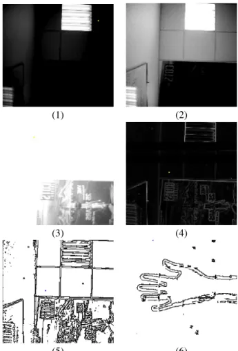
Figure 3(1-3) shows the 3 resulting images Bt, Mtand Dt.
Recomposing a high dynamic range image from these 3 im-ages, or reducing the representation of the image (e.g. from 3log(n) to log(n) bits) can be done using different techniques that have been addressed in the literature [4] [6]. But in our application, we do not wish to recompose an image, but only to estimate the local contrast to compute the contour. We then simply compute a reduced representation of the con-trast by computing the maximum of the local concon-trast in the 3 images:
GtB= max(gB(Bt), gB(Mt), gB(Dt))
where gBis the morphological gradient (see Section 3).
Some other results that have been achieved by using the artificial retina can be found in the [2] and [10] papers.
3 Moving Contour detection
The static part of the algorithm used in the detection of the moving contours is based on the morphological edge detec-tor described by Lee et al in [9]. This non-linear framework, using essentially min and max operations, is well suited to the Boolean computational model of the programmable retina. The morphological edge detection provides a mea-sure of local contrast within every pixel, thanks to the dila-tion residue operator: let f (x, y) be a grayscale image and b the structuring element, which is a set containing the origin (0, 0). The dilation of f by b if defined as:
( f ⊕ b)(x, y) = max
(i, j)∈bf (x − i, y − j)
The edges obtained by using the dilation residue, or (dilation-) gradient, noted by gb(x, y), will be:
gb( f )(x, y) = ( f ⊕ b)(x, y) − f (x, y)
Like [9], we combine different gradients ob-tained using several structuring elements: gB( f ) =
min(gb1( f ), ..., gbn( f )), in order to be less sensitive to
noise and edge orientation. And according to Section 2, we maximize the gradient over the three acquired images:
Gt
B= max(gB(Bt), gB(Mt), gB(Dt)): see Figure 3(4).
Once the (grayscale) edge map computed, we get the (binary) contours by employing a non-maximal suppresion technique, adapted from [3] to suit the massive parallelism of the retina. The method of suppresion is the following: let
p be the pixel that is currently being processed (do not forget
that the other 39,999 pixels of the retina are simultaneously
undergoing the same sequence of operations) and his twelve neighbours, denoted using cardinal directions indices as fol-lows: pNN pNW pN pNE pWW pW p pE pEE pSW pS pSE pSS
p will be selected as a contour point if at least one of the
following four conditions is true:
1. pNW+ pW+ pSW < pN+ p + pS> pNE+ pE+ pSE
(corresponding to a horizontal ridge)
2. pNW+ pN+ pNE< pW+ p + pE> pSW+ pN+ pSE
(corresponding to a vertical ridge)
3. pNN+ pNW+ pWW< pNE+ p+ pSW> pEE+ pSE+ pSS
(corresponding to a ridge with an orientation of 135◦) 4. pWW+ pSW+ pSS< pNW+ p+ pSE> pNN+ pNE+ pEE
(corresponding to a ridge with an orientation of 45◦)
After this local maxima selection two last operations are completed to compute the contour image Ct: first, the
con-tour with a gradient value of 1 are discarded to avoid the fake edges induced by the quantization effect on a grayscale ramp (those for example, due to the vignetting effect of the lens). Then, to eliminate salt-and-pepper-like detections, we also impose the condition that a pixel can be taken into account as a contour pixel only if it has at least two neighbours classified as contours too. This gives a lower rate of false detections, although it lowers the quantity of information theoretically obtainable from an image. Figure 3(5) shows an example of contours image.
To discriminate the moving contours from those of the static scene, we need to compare the current occurrences with the past edges. The basic approach is the following one: we keep track of the number of times when a pixel was a contour, by computing, for any instant t, two de-scriptors attached to every pixel, and related to two differ-ent timescales: the short term history (STH) and the long term history (LTH). At every frame, if the pixel belongs to an edge, then STH is increased. If not, it is decreased. The increment/decrement is adjusted to not exceed the interval allowed by the dynamics of STH. The update for the LTH is almost the same, except that instead of the contour Ct, the
most significant bit of STH is used, and the timescale (i.e. the update period) is larger.
The computation of the moving contours is obtained from a logical AND between the current contour Ctand the pixels
with a low LTH. As, obviously, a pixel can belong to both the contour of a moving object and the contour of the static scene, one iteration of reconstruction (or geodesic dilation) is performed: a dilation is computed on the intersection set, followed by a logical AND with Ct. This step allows to limit
the disconnection on the resulting moving contours image
Et. The relevance of this basic approach is based on the fact
that - by construction - the contours are one-pixel-thick, and then an object must be very still to let his contours be taken into account by the LTH. To enhance this behavior, however, and avoid the blurry, low-value disturbances which may be caused by the contours of a moving object in STH, we lower the increment frequency in STH for the pixels belonging to
Et.
Another problem in the basic approach is generated by the fact that, generally, the moving objects are not transpar-ent, which makes possible for a part of the background con-tours to be erased by the overlapping objects. The solution has been provided by the introduction of discrimination be-tween the increment and the decrement of the LTH, the latter being discouraged. Thus, even if an object is obstructing the background scenery for a large amount of time (adjustable through parameterisation), it is possible for the object’s con-tours to integrate themselves in the background (if the object is standing still) and, at the same time, for the background contours to stay longer in the scene, as if the new object was transparent. This property, together with the intrinsic thin-ness of the contours, significantly reduces the “ghost effect” (part of the static scene appearing as moving contours after being covered for a long time by a moving object). See Fig-ure 3(6) for an example of moving contours image.
The measured times of execution for the different parts of the algorithm are the following: 10ms are needed by the retina to do its job (determination of the gradients, update of STH and LTH, extraction of moving contours, etc.), 8.6ms are needed for the ARM to compute the new trace (see Sec-tion 4) and 50ms are necessary to acquire the three initial im-ages. The time needed to capture the three images is largely scene-dependent, a darker scene will demand a longer expo-sure time. As one can observe, the bottleneck is not induced by the processors in the retina themselves, but by the images’ capture time. From an energetic point of view, the power consumption of the system is only a few tens milliwatts, 3 to 4 orders of magnitude as small as that of a PC.
Because of the high sensitivity induced by this algorithm, we get some false detections in addition to the true contours of the moving objects. Since some local filtering has already been applied, those false detections are gathered into small connected components. As objects of interest generally have important areas, we reduce the number of false alarms by filtering out small regions. This requires non-local compu-tations on the image, surpassing the present possibilities of the retina. Thus, this step is performed by the host (ARM) processor. The further analysis, consisting in extracting and exploiting regional and global quantities on the moving con-tours is discussed in the next section.
4 Vision-based interface
The purpose of the image processing techniques pre-sented above is to allow a stable and complete extraction of the contours of the moving objects, without imposing con-straint of uniformity in the background. With respect to the input data flow, this feature represents a small amount of data which can be quickly extracted from the retina and processed by the external processor. We are currently beginning the exploitation of this visual feature for higher level process-ing. We present in this section the first experiments of visual interaction we have performed.
In these experiments, we are testing a drawing interface: the user draws a bidimensional curve by moving his finger or a pen above the retina, which is oriented toward the ceil-ing. Such interface can be used to input hand drawn
char-(1) (2)
(3) (4)
(5) (6)
Figure 3. Acquisition and processing within the pro-grammable retina: (1) short exposure acquisition Bt.
(2) medium exposure acquisition Mt. (3) long exposure
acquisition Dt. (4) maximum of the morphological
gra-dient over the three acquisitions GB
t. (5) binary contours
Ct. (6) moving contours detected Et.
acters or sketches [5], but also some simple hand gestures [8], for which the curve represents a 2d model to be further processed and recognized.
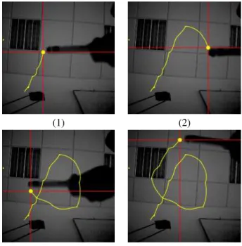
One difficulty in developping visual interface is the neces-sity of several modalities in the interaction, just like the ac-tion of a mouse stops if it is dropped, or changes if its button is depressed. We wish to use the visual interface alone, with-out interaction of the mouse or keyboard. This implies that several parameters of the visual feature must be exploited, in order to define not only the position of the “tool”, but also the action modality. In our example, the 3 modalities are (1) Draw, (2) Do nothing, (3) Erase.
So the first parameter computed from the visual feature is a global one ; it is the orientation of the moving object. Like [1], we compute the second order moments (vx, vy),
i.e. the variances of the two coordinates of the moving con-tour points. The rough orientation is then used to define the modality: if vx/vyis superior to a given threshold σD, then
the “Draw” action is selected. If vy/vxis superior to a given
the “Do nothing” action is selected.
The second parameter extracted from the moving contour is a local one: the extreme left position of the moving ob-jects, if any (there must be a connected curve with at least
Nminpoints) is used as the candidate position of the tool. This
candidate position is checked according to a predictive filter-ing (it must not be too far from the previous position of the same tool). If the position is confirmed, then the following action is applied on the drawing widget: if “draw” is selected then create a line between previous and current position ; if “erase” is selected, then erase all points situated at the right of the current position.
On Figure 4, we can see the tracking system in action. Special attention should be paid to the transitions over the very textured areas (the neon grid, for instance). Because we work with contours only, we could expect some difficul-ties when crossing these areas, but by using a wisely chosen set of filters (enclosure and selection based on the elements’ size), we are able to obtain a very high detection rate of the fingertip.
(1) (2)
(3) (4)
Figure 4. Drawing example using the visual mouse
5 Conclusion
We have presented in this paper a project of visual inter-face based on the extraction and processing of the contours of the moving objects. At the moment, we have mainly devel-opped the low-level part of the project, which corresponds to the extraction of the moving contours, using a programmable retina, both as camera and parallel computer. The combi-nation of acquisition and image processing allows a smart adaptation to the lighting properties of the scene. The vi-sual interaction can be seen as a huge data reduction, turn-ing video flow into symbols. The computational model of the programmable retina limits the data transfers to the min-imum, and then reduces the energy consumed by this data
reduction.
The higher level (interpretation of the moving contours) is being investigated, and will be pursued in the following months. We have presented our first experiments, based on single point/multiple actions interface. The perspectives of this work are also: global hand posture estimation for con-trolling a 3d mouse, and traking a 3d model to recover the complete posture of the arm/hand/fingers.
6 References
[1] S. Ahmad. A usable real-time 3d hand tracker. In 28th
Asilomar Conference on Signals, Systems and Comput-ers, pages 1257–1261, 1995.
[2] N. Burrus and T.M. Bernard. Adaptive vision lever-aging digital retinas: Extracting meaningful segments. In Advanced Concepts for Intelligent Vision Systems, pages 220–231, 2006.
[3] B. Chanda, M.K. Kundu, and Y.V. Padmaja. A multi-scale morphologic edge detector. Pattern Recognition, 31(10):1469–1478, 1998.
[4] P. Debevec and J. Malik. Recovering high dynamic range radiance maps from photographs. In SIGGRAPH
97, pages 369–378, aug 1997.
[5] I.A. Erdem, M.E. Erdem, V. Atalay, and A.E. C¸etin. Vision-based continuous graffiti-like text entry system.
Optical Engineering, 43:553–558, 2004.
[6] R. Fattal, D. Lischinski, and M. Werman. Gradient do-main high dynamic range compression. In ACM
SIG-GRAPH 2002, pages 249–256, july 2002.
[7] R. Forchheimer and A. Astrøm. Near-sensor image processing: a new paradigm. IEEE trans. on Image
Processing, 3:736–746, 1994.
[8] T. Huang and V. Pavlovic. Hand gesture modeling, analysis, and synthesis. In International Workshop on
Automatic Face and Gesture Recognition, pages 73–79,
1995.
[9] J. Lee, R. Haralick, and L. Shapiro. Morphologic edge detection. IEEE Journal of Robotics and Automation, 3:142–156, 1987.
[10] J. Richefeu and A. Manzanera. A morphological dom-inant points detection and its cellular implementation. In ISSPA 2003 Proceedings, volume 2, pages 181–184, 2003.
[11] J. Serra. Image analysis and mathematical
morphol-ogy. London Academic, 1982.
[12] B. Zavidovique and G. Stamon. Bilevel processing of multilevel images. In Pattern Recognition and Image