HAL Id: tel-01980728
https://tel.archives-ouvertes.fr/tel-01980728v2
Submitted on 11 Dec 2018HAL is a multi-disciplinary open access archive for the deposit and dissemination of sci-entific research documents, whether they are pub-lished or not. The documents may come from teaching and research institutions in France or abroad, or from public or private research centers.
L’archive ouverte pluridisciplinaire HAL, est destinée au dépôt et à la diffusion de documents scientifiques de niveau recherche, publiés ou non, émanant des établissements d’enseignement et de recherche français ou étrangers, des laboratoires publics ou privés.
for automated composite lay-up process
Jiuchun Gao
To cite this version:
Jiuchun Gao. Optimal motion planning in redundant robotic systems for automated composite lay-up process. Mechanical engineering [physics.class-ph]. École centrale de Nantes, 2018. English. �NNT : 2018ECDN0015�. �tel-01980728v2�
T
HESE DE DOCTORAT DE
L'ÉCOLE
CENTRALE
DE
NANTES
C
OMUEU
NIVERSITEB
RETAGNEL
OIREECOLE DOCTORALE N°602
Sciences pour l'Ingénieur Spécialité : Génie mécanique
Par
Jiuchun GAO
T
HESE DE DOCTORAT DE
L'ÉCOLE
CENTRALE
DE
NANTES
C
OMUEU
NIVERSITEB
RETAGNEL
OIREECOLE DOCTORALE N°602
Sciences pour l'Ingénieur Spécialité : Génie mécanique
Optimal Motion Planning in Redundant Robotic Systems for
Automated Composite Lay-up Process
Thèse présentée et soutenue à Amphithéâtre S, Ecole Centrale de Nantes, le 29 juin 2018 Unité de recherche : Laboratoire des Sciences du Numérique de Nantes (LS2N)
Composition du Jury : Président
Benoît Furet Professeur des universités, Université de Nantes Gabriel Abba Professeur des universités,
Université de Lorraine
Hélène Chanal Maître de conférences HDR, Institut français de mécanique avancée, Aubière Sylvain Miossec Maître de conférences, IUT Bourges Directeur de thèse
Anatol Pashkevich Professeur, IMT-Atlantique Co-directeur
Stéphane Caro Chargé de recherche-HDR, CNRS Invité
Claire Dumas Ingénieur de recherche, Daher Aerospace Rapporteurs avant soutenance :
Gabriel Abba Professeur des universités, Université de Lorraine
Hélène Chanal Maître de conférences HDR, Institut français de mécanique avancée, Aubière
ACKNOWLEDGEMENTS
Before beginning this manuscript, I would like to express my gratefulness to people who have guided and helped me in my research and who have provided all possible assistance throughout the time of working on the thesis.
First and foremost I am sincerely thankful to my supervisor, Professor Anatol Pashkevich, for his continuous support of my Ph.D study and research. It is difficult to assess his contribution in my work. He always directed my work in a right way, gave invaluable advices, and spent plenty of time to improve my thesis quality and the research significance. He taught me to write high-quality scientific papers and carry out independent research.
Special thanks also goes to my another supervisor, Dr. Stéphane Caro, for his insightful comments, patience and encouragement. His guidance helped me in all the time of my study and research. It is also an honor for me to thank the members of the “Comité de suivi” Dr. Sylvain MIOSSEC and Dr. Mathieu RITOU for their help and precious suggestions.
I am grateful for all conversations and discussions with my colleague Dr. Alexandr Klimchik who always gave reasonable answers and high quality advices when I met difficulties during my first year. In addition, I thank Mr. Divya Shah for his significant contribution to the simulations.
I also would like to thank our industrial partner from CETIM Alain Lemasçon, Benoît Courtemanche and Julien Lefort. They provided me technological advices and gave the opportunity to evaluate experimentally my theoretical work on a real robotic platform.
The last and most important thank goes to my family, who always supported me in all my pursuits. I would like to thank them for all their love and encouragement.
ABSTRACT AND KEYWORDS
Abstract: The thesis deals with the optimal motion planning in redundant robotic systems for automation of the composite lay-up processes. The primary goal is to improve the lay-up workcell productivity by developing a novel methodology of optimizing coordinated motions of the robotic manipulator, workpiece positioner and workspace extension unit, which ensure the shortest processing time and smooth movements of all mechanical components. In contrast to the previous works, the proposed methodology provides high computational efficiency and also takes into account both the technological constraints and the robotic system constraints, which describe capacities of the actuators and are expressed by the maximum allowable velocities and accelerations in the actuated joints. The developed technique is based on conversion of the original continuous problem into a combinatorial one, where all possible configurations of the mechanical components are represented as a directed multi-layer graph and the desired time-optimal motion is generated using dynamic programming principle for searching the shortest path on the graph satisfying the smoothness constraints. It is also proposed an enhancement of this technique by dividing the optimization procedure in two stages combining global and local searches. At the first stage, the developed algorithm is applied in the global search space generated with large discretization step. Then, the same technique is applied in the local search space, which is created with smaller step in the neighborhood of the obtained trajectory. Alternatively, the second stage may implement a straightforward smoothing of the redundant variable profiles. The advantages of the developed methodology are confirmed by industrial implementation on the factory floor that deals with manufacturing of the high-pressure vessel.
Keywords: Redundant robotic system, Motion planning, Time-optimal trajectory, Dynamic programming, Automated composite lay-up
CONTENTS
ACKNOWLEDGEMENTS ... i
ABSTRACT AND KEYWORDS ... ii
GENERAL INTRODUCTION ... v
FIGURES ... ix
TABLES ... xii
CHAPTER 1 ROBOT-BASED FIBER REINFORCEMENT TECHNOLOGY IN INDUSTRY ... 1
1.1 COMPOSITES PARTS FABRICATION TECHNIQUES ... 2
1.1.1 Composite Materials in Manufacturing ... 2
1.1.2 Automation of Composite Products Manufacturing ... 5
1.1.3 Industrial Systems for AFP Based Composite Manufacturing ... 12
1.2 REDUNDANCY RESOLUTION IN ROBOTIC SYSTEMS ... 14
1.2.1 Redundancy Resolution via Generalized Inverse of the Kinematic Jacobian ... 15
1.2.2 Redundancy Resolution via Coordinating of Robot/Positioner Motions ... 17
1.2.3 Optimization Based Techniques for Redundancy Resolution ... 19
1.3 ROBOTIC CELL DESIGN AND PROGRAMMING FOR COMPOSITE PRODUCT MANUFACTURING ... 24
1.3.1 Manufacturing Process Planning for Robotic Lay-up Applications ... 24
1.3.2 Software Packages for Computer Aided Design of Industrial Robotic System ... 27
1.4 THESIS GOAL AND RESEARCH PROBLEMS ... 30
CHAPTER 2 ROBOTIC LAY-UP SYSTEM MODEL AND MOTION GENERATION PROBLEM FORMALIZATION ... 32
2.1 LAY-UP TASK DESCRIPTION AND ITS CREATION IN CAD SYSTEM ... 33
2.1.1 Representation of the Lay-up Task in the Form of the Sequence of 4×4 matrices... 33
2.1.2 Conversion of the Lay-up Task to the Sequence of 6×1 vectors ... 35
2.2 ROBOTIC LAY-UP SYSTEM COMPONENTS AND THEIR MODELS ... 36
2.2.1 Kinematic Model of Robotic Manipulator ... 36
2.2.2 Kinematic Model of Actuated Positioner ... 48
2.2.3 Integrated Kinematic Model of the Robotic Lay-up System ... 51
2.3 MOTION GENERATION IN ROBOTIC LAY-UP SYSTEM ... 53
2.3.1 Formalization of Motion Planning Problem for Robotic Lay-up System ... 54
2.3.2 Additional Constraints from the Actual Robotic System ... 56
2.4 SUMMARY ... 65
CHAPTER 3 MOTION PLANNING FOR ROBOTIC LAY-UP SYSTEM ... 66
3.1.1 Search Space Discretization for One Redundant Variable ... 67
3.1.2 Search Space Discretization with Two Redundant Variables ... 73
3.2 MOTION PLANNING METHOD BASED ON COMBINATORIAL OPTIMIZATION ... 77
3.2.1 Straightforward Approaches and Related Difficulties ... 77
3.2.2 Motion Generation using Dynamic Programming Technique... 79
3.3 ENHANCEMENT OF THE MOTION PLANNING ALGORITHM ... 82
3.3.1 First Strategy: Progressive reduction of the discretization step... 82
3.3.2 Second Strategy: Smoothing the redundant variable profiles... 84
3.3.3 Performance Evaluation of the Enhanced Algorithms ... 86
3.4 PARAMETERS TUNING FOR MOTION PLANNNING ALGORITHM ... 91
3.4.1 Influence of Discretization Step on the Generated Trajectories ... 91
3.4.2 Practical Recommendations for Selecting the Discretization Step ... 93
3.5 SUMMARY ... 95
CHAPTER 4 EXPERIMENTAL VALIDATION AND INDUSTRIAL IMPLEMENTATION ... 96
4.1 MANUFACTURING PROCESS PREPARATION FOR HIGH-PRESSURE VESSEL FABRICATION... 97
4.1.1 Manufacturing Task Description and its Regularization ... 97
4.1.2 Selection of Robotic System Components and Workcell Lay-out Design ... 100
4.2 ROBOTIC SYSTEM MOTION PLANNING USING DEVELOPED ALGORITHMS ... 103
4.2.1 Generation of the Task Graph for the Thermoplastic Tape Lay-up ... 103
4.2.2 Generation of Time-optimal Coordinated Motions of Robot and Positioner ... 108
4.3 OPTIMAL MOTION IMPLEMENTATION IN ROBOTIC SYSTEM ... 112
4.3.1 Motion Implementation using KRL Robot Programming Language ... 112
4.3.2 Experimental Evaluation of the Implemented Time-Optimal Motions ... 116
4.4 SUMMARY ... 120
CONCLUSIONS AND PERSPECTIVES ... 121
CONTRIBUTION OF THE THESIS ... 121
LIMITATIONS OF THE OBTAINED RESULTS ... 122
PERSPECTIVES AND FUTURE WORK ... 123
PUBLICATIONS ... 124
GENERAL INTRODUCTION
Motivation. At present, composite materials are increasingly used in engineering practice. Compared to traditional ones, they have good strength-to-weight ratio, durability, flexibility of shaping and corrosion resistance (Christensen, 2012, Jones, 1998, Kaw, 2005, Lubin, 2013, Peters, 2013). For these reasons, they are extremely attractive for fabrication of large dimensional parts in aerospace, automotive and marine industries (Gay, 2014, Marsh, 2011).
A conventional way of manufacturing such composite components is based on the manual lay-up process. However, this labor-intensive procedure is quite slow, expensive and does not allow achieving required repeatability (Marsh, 2011). An alternative solution implementing such process is usually based on automated lay-up of the composite tape or fiber, which are placed layer-by-layer to ensure full coverage of the relevant surface. Compared to manual techniques, such automated lay-up processes ensure higher productivity, repeatability and better product quality.
The automated lay-up processes can be implemented by using either specifically designed machines or robotic systems, which in this application are usually redundant. In the first case, general CNC machines equipped with specific lay-up head are used. They have no essential limitations on the workpiece size, but usually are quite expensive and require large work floor areas (Gallet-Hamlyn, 2011, Rabeneck, 2010). Compared to the process-dedicated machines, the robotic systems composed of a 6-axis serial robot (mounted on a linear track/gantry), an actuated positioner and a dedicated technological tool are relatively cheap and flexible allowing changing the product type easily (Krombholz et al., 2012, Shirinzadeh et al., 2004). For these reasons, the robotic lay-up systems are increasingly used in practice. However, the manufacturing process planning and manipulator motion programming for such robotic systems is not trivial. The main difficulty here arises because the kinematic redundancy of the robotic system, which usually contains two extra degrees of freedom provided by the rotational positioner and the translational unit (linear track or gantry). This redundancy does not allow generating the manipulator trajectories straightforwardly and also complicates robot programming, which is still a challenge in productivity improvement for the automated lay-up process. On the other hand, the redundancy gives user some flexibility in motion planning and optimal utilization of the actuator capabilities allowing generating faster trajectories.
In robotic literature, the issue of the kinematic redundancy resolution has been studied for several decades. A conventional way is based on the pseudo inverse of the kinematic Jacobian (Flacco and De Luca, 2015, Kazerounian and Nedungadi, 1988, Wu et al., 2000, Buss, 2004). It provides a unique solution for the differential kinematic equations in the sense of least squares corresponding to the smallest Euclidean norm of the displacement vector in the joint space. Some other approaches (Tabarah et al., 1994, Gan et al., 2013, Gan et al., 2012) for non-complex shape tasks are based on coordinating of robot/positioner motions, where the motions of the “master” are assigned firstly and the conjugate trajectories of the “slave” are then determined. For complex shape workpiece taking into account constraints imposed by actuators, several alternative optimization based methods have been developed for the spot-welding application (Gueta et al., 2011a, Gueta et al., 2011b). They are based on converting the original problem into a discrete form, where the robotic manipulator and the positioner joint spaces are discretized and desired trajectory can be represented as a path on the corresponding graph. Slightly different approach was proposed in (Dolgui and Pashkevich, 2009, Pashkevich et al., 2004) for the laser cutting applications. It minimizes the oscillation in actuator
velocities when assuming the tool speed is constant. Hence, the known techniques cannot be straightforwardly applied to the considered lay-up technology where the robot tool speed should be as high as possible. Besides, required functionality is not included in existing commercial software packages (such as Robcad, Robotmaster, CATFiber, etc) allowing generating certain coordinated motions for the redundant robotic systems. For these reasons, the problem of optimal motion planning for robotic lay-up systems becomes very important and corresponds to current needs of the composite product fabrication technology.
Thesis goal and research problems. The thesis focuses on the optimal motion planning in redundant robotic systems allowing improving the productivity of the automated composite lay-up workcell. Special attention is paid to the motion coordination of the robotic manipulator, workpiece positioner and workspace extension unit, which ensures the shortest manufacturing time and smooth movements of all mechanical components. To achieve this goal, the following tasks have to be solved:
Task #1:
Analysis of existing systems for composite product manufacturing, detecting their weak points and comparative study of known methods for the motion planning in redundant robotic systems.
Task #2:
Creating kinematic model of a typical redundant robotic system used in the composite lay-up technology and formalization of the related optimal motion planning problem.
Task #3:
Development of the method for the optimal coordinated motion planning in the redundant robotic system composed of the robotic manipulator, workpiece positioner and workspace extension unit, which allows minimizing the total motion time and ensuring smooth movements of all mechanical components.
Task #4:
Application of the developed algorithms to real industrial problems, development of the robot control programs implementing generated time-optimal trajectories, simulation of the coordinated movements in 3D environment, and experimental validation of the developed techniques on the factory floor.
Thesis organization. To solve the above defined tasks, the thesis is organized as follows:
Chapter 1 presents the state of the art in the field of robot based composite lay-up technology and describes existing techniques of motion planning in robotic systems with kinematic redundancies. The main purpose of this chapter is to detect the weak points of existing methods and justify necessity of developing of new ones, which allow defining the thesis main goal and related research problems.
Chapter 2 focuses on the kinematic modeling of a typical redundant robotic system used in the composite lay-up technology and formalization of the related optimal motion planning problem. The considered problem is presented as finding of the time-optimal trajectory in robotic system joint space
under specific constraints related to both the robotic system and technological task. These constraints allow taking into account limitations of the robotic system (joint limits, maximum joint velocities/accelerations), practical requirements for the manipulator postures (via singularities and collision constraints) as well as the Cartesian path constraints issued from the composite lay-up process. The main purpose of this chapter is to formalize the considered technological problem and to present it in the form common for the mathematical optimization theory.
Chapter 3 is devoted to the development of a new motion planning method for the redundant robotic systems utilized in the automated composite lay-up process. It is based on the transforming the original problem into a combinatorial one and applying the dynamic programming principle. First, the task graph is created by discretizing the redundant variables and sequentially applying to all task locations the direct kinematics of the positioner (and workspace extension unit) as well as inverse kinematics of the robot. Then, the developed algorithm based on dynamic programming generates the time-optimal motion taking into account all relevant constraints. To reduce the computing time, the time-optimal motion planning is divided in two stages combining global and local searches. At the first stage, the developed algorithm is applied in the global search space generated with large discretization step. Then, the same technique is applied in the local search space, which is created with smaller step in the neighborhood of the obtained trajectory. Alternatively, the second stage may implement a straightforward smoothing of the redundant variable profiles. Efficiency of them and advantages compared to the conventional techniques are confirmed by several case studies.
Chapter 4 deals with industrial implementation of the developed motion planning method on the factory floor (for manufacturing of a high-pressure vessel). Using the proposed method, there were generated time-optimal smooth motions for the manipulator and positioner of the SPIDE-TP robotic platform allowing speeding up the thermoplastic tape lay-up process. Correctness of these motions was verified in 3D simulation environment of CATIA software package. Besides, it was created a program in KRL language implementing these motions and ensuring coordinated control of KUKA KR210 robot and AFPT workpiece positioner. There are presented results of industrial experiments carried out with this program, which confirmed smoothness of the manipulator/positioner movements and essential reduction of the time required for the thermoplastic tape lay-up process.
Finally, Conclusion summarizes the main contributions of the thesis and defines perspectives for future research work.
Main contributions of the thesis. Theoretical contributions of this thesis are in the area of redundancy resolution and time-optimal motion planning for robotic systems composed of the robotic manipulator, workpiece positioner and workspace extension unit. The most essential results can be summarized as follows:
(i) Formalization of the optimal motion planning problem for typical robotic lay-up platforms. The proposed approach presents the considered problem as finding of the time-optimal trajectory in the joint space of the robotic system under specific constraints related to the technological task. The latter include both conventional kinematic constraints (joint limits, maximum joint velocities/accelerations), allowable distances to the singularities and obstacles as well as the Cartesian path constraints issued from the composite lay-up process.
(ii) A new method of coordinated time-optimal motion planning for redundant robotic systems ensuring smooth movements of all mechanical components. It is based on transformation of the original optimization problem into a combinatorial one and application of the dynamic programming principle. At the first stage, the redundant variables are discretized and the task graph is created by sequentially applying to all task locations the direct kinematics of the positioner (and workspace extension unit) as well as inverse kinematics of the robot. Then, the developed optimization algorithm based on dynamic programming generates the time-optimal motion taking into account all constraints related to the system kinematics and considered technology. Efficiency of the developed method and its advantages compared to the conventional techniques are confirmed by several case studies.
(iii) Enhancement strategies for the developed motion planning method. To reduce the computing time required for the motion planning, it was proposed to avoid combinatorial search in high-dimensional space. To achieve this target, the time-optimal motion planning is divided in two stages combining global and local searches. At the first stage, the developed algorithm is applied in the global search space generated with relatively large discretization step. Then, the same technique is applied in the local search space, which is created with small discretization step in the neighborhood of the trajectory obtained at the previous stage. As an alternative, the second stage may implement a straightforward smoothing of the redundant variable profiles based on the spline approximation. As follows from relevant study, the proposed enhancement strategies allow essentially reducing the computing time, down to the level acceptable in engineering practice.
(iv) Application of the developed optimal motion planning method to real industrial problems. Using the thesis results, there were generated time-optimal smooth motions for the manipulator and positioner of the SPIDE-TP robotic platform allowing speeding up the thermoplastic tape lay-up process for manufacturing of the composite high-pressure vessel. For these motions, it was created a program in KRL language ensuring coordinated control of KUKA KR210 robot and AFPT workpiece positioner. Experimental evaluation of the motions described by this program confirmed smoothness of the manipulator/positioner movements and essential reduction of the time required for the thermoplastic tape lay-up process.
Dissemination of research results. The main results obtained in this thesis have been published in four works and have been presented in three international conferences. Among them, there is a paper in an international journal (Mechanism and Machine Theory) and three papers in international conference proceedings (EUCOMES’2016 - European Conference on Mechanism Science of IFTOMM, ICMIT’2017 - International Conference on Manufacturing and Industrial Technologies, and ICOME’2017 - International Conference on Mechanical Engineering).
The scientific contribution of this thesis have been developed and validated experimentally in the framework of strong cooperation with R&D Department of Polymer and Composite of the technical center CETIM (Centre Technique des Industries Mécaniques), Nantes.
FIGURES
Figure 1 Components of typical fiber reinforced composite material ... 2
Figure 2 Strength plotted against density (yield strength for metals and polymers; compressive strength for ceramics, tear strength for elastomers and tensile strength for composites) (Ashby and Cebon, 1993) ... 3
Figure 3 Composite materials are used to make pressure tanks ©MATERIA (http://www.materia-inc.com/) ... 4
Figure 4 Composite materials used throughout the body of the Boeing 787 ©BOEING (https://www.comsol.com) ... 4
Figure 5 Common PMCs manufacturing processes in industry ... 7
Figure 6 Typical filament winding process © CONNOVA (www.connova.com/) ... 8
Figure 7 Typical automated tape laying system © MTORRES (www.mtorres.com/) ... 10
Figure 8 ATL for Boeing787’s unique one-piece composite barrel construction ©BOEING (https://www.boeing.com) ... 10
Figure 9 Schematic of automated tape laying and automated fiber placement ... 11
Figure 10 Automated fiber placement process for fuselage section producing with window cut-outs © MTORRES (www.mtorres.com/) ... 11
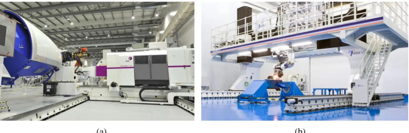
Figure 11 (a) Cincinnati VIPER™ platform for automated fiber placement, © Cincinnati VIPER™ (b) TORRESFIBERLAYUP machine for automated fiber placement, © MTorres. ... 12
Figure 12 Robot-based AFP system developed by Coriolis Composite © Coriolis Composite (www.coriolis-composite.com) ... 13
Figure 13 (a) Robot-based AFP system with modular head developed by Electroimpact, ©Electroimpact (b) Robot-based AFP system in the Composites Technology Center of NASA, ©NASA ... 13
Figure 14 Redundant robotic system for application example ... 16
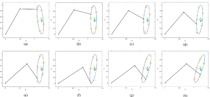
Figure 15 Simulation of the solution from pseudo-inverse for planar redundant robotic system: (a) (h) ... 17
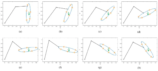
Figure 16 Simulation of the solution from motion coordination for planar redundant robotic system: (a) (h) ... 19
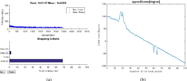
Figure 17 (a) visualization of the GA progress for considered application example; (b) Joint coordinates of the positioner from GA based solution. ... 23
Figure 18 Manufacturing process planning for robotic lay-up processes... 25
Figure 19 Typical fiber placement curves defined in 3D CAD model (SolidWorks), with position and normal direction relative to the workpiece frame ©AUTOMATED DYNAMICS® (www.automateddynamics.com). ... 33
Figure 20 Definition of task frames with respect to workpiece frame ... 34
Figure 21 Architecture of standard 6-axis industrial robot ... 37
Figure 22 Different configuration of robotic manipulator for the same location of the end-effector ... 40
Figure 23 Three types of singular configurations in KUKA kinematic system, ©KUKA (KUKA, 2010) ... 43
Figure 24 Projection of the manipulator links on the vertical plane (Configuration SHOULDER_FORWARD & ELBOW_UP) ... 44
Figure 25 Multiple manipulator configurations for the same wrist center point position ... 44
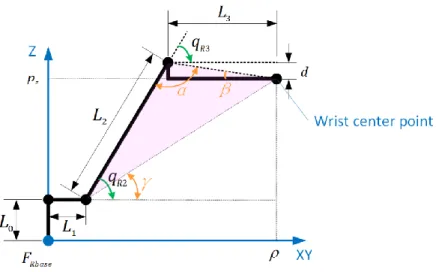
Figure 26 Triangles highlighted for computing the angle of axis #2 ... 45
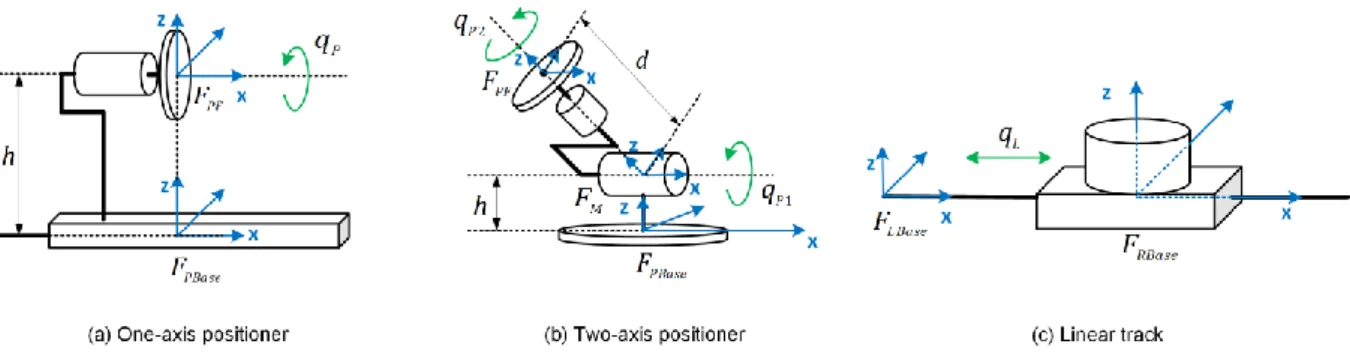
Figure 27 Typical one-axis positioners from KUKA (www.kuka.com) ... 48
Figure 29 Typical linear track and gantry from KUKA (www.kuka.com) ... 49
Figure 30 Kinematics of typical one-axis positioner, two-axis positioner and linear track ... 50
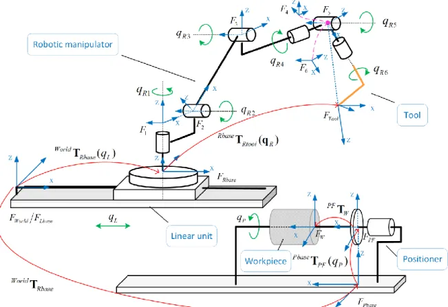
Figure 31 Integration of the robot and the positioner kinematic models ... 52
Figure 32 Schematic of motion generation in robotic lay-up system ... 53
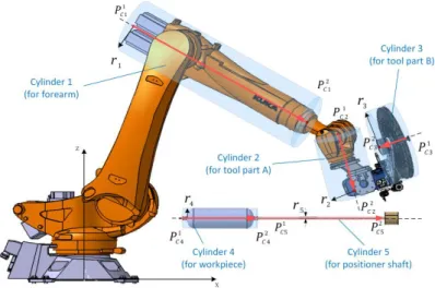
Figure 33 Collision detection based on intersection of two cylinders ... 57
Figure 34 Cylinder-based descriptions of the workcell components for collision detection... 59
Figure 35 Triangle-based description of the workcell components for collision detection... 60
Figure 36 Situation of two triangle planes intersecting at a straight line ... 61
Figure 37 Structural presentation of the robotic lay-up workcell in CATIA, and component pairs selected for collision detection ... 62
Figure 38 Strategy of verifications on the additional constraints ... 64
Figure 39 Transformation of the motion planning problem into discrete form (case of one redundant variable) ... 68
Figure 40 Directed graph describing the motion planning problem with one redundant variable ... 69
Figure 41 Motion synchronization in a typical robot controller ... 71
Figure 42 Superposition of the velocity profiles for continuous motions ... 72
Figure 43 Transformation of the motion planning problem into discrete form (case of two redundant variables) ... 74
Figure 44 Directed graph describing the motion planning problem with two redundant variables ... 75
Figure 45 Directed graph with two virtual vertices for the motion planning problem ... 77
Figure 46 Combination of the rough search and the local optimization ... 82
Figure 47 Search space evolution for the two-stage algorithm ... 83
Figure 48 Combination of the rough search and smoothing of the redundant variable profiles ... 85
Figure 49 Enhanced algorithm #1: trajectories obtained at the Stage I (ΔqP = 3°, Tmotion = 9.44s) ... 89
Figure 50 Enhanced algorithm #1: trajectories obtained at the Stage II (ΔqP = 0.5°, Tmotion = 7.63s) .. 89
Figure 51 Enhanced algorithm #2: trajectories obtained at the Stage II (ΔqP = 1°, Tmotion = 8.47s) .... 90
Figure 52 Enhanced algorithm #2: trajectories obtained after smoothing (Tmotion = 8.47s) ... 90
Figure 53 A benchmark task for investigating the influence of ΔqP ... 91
Figure 54 Evolution of robotic system motion time with reduction of different discretization step ΔqP ... 92
Figure 55 A portion of the task graph corresponding to the task locations 17, 18 and 19 ... 93
Figure 56 A sample of the lay-up path and its execution by the robot and the positioner ... 94
Figure 57 The high-pressure vessel with thermoplastic fiber covering, ©CETIM. ... 97
Figure 58 A sample of the laying task for a high-pressure vessel, ©CETIM... 98
Figure 59 Discrete representation of the lay-up task in the form of the augmented line ... 98
Figure 60 Regularization of the lay-up task discrete model (smoothing and replacing an irregular step 1.5 to 21.0 mm by the regular step 8.0 mm) ... 99
Figure 61 SPIDE-TP platform for manufacturing high-pressure vessels, ©CETIM. ... 100
Figure 62 Technological tool used in SPIDE-TP platform, ©CETIM. ... 100
Figure 63 Work envelop of robot KUKA KR210 R3100 ultra, ©KUKA GmbH ... 101
Figure 64 Selecting the optimal robot location on the linear track... 102
Figure 65 Robotic platform SPIDE-TP and arrangement of coordinate frames ... 103
Figure 66 Task graph evolution after applications of kinematic and collision constraints (“blue”− admissible vertices; “white” − inadmissible vertices; “red” − admissible path). ... 106
Figure 67 Collisions between different components of robotic platform SPIDE-TP ... 107
Figure 68 Procedure of fine collision detection in CATIA environment ... 107
Figure 69 Profiles of time-optimal motion for thermoplastic fiber covering of the high-pressure vessel ... 109
Figure 70 Bottleneck areas at the task graph (too close to collisions)... 110
Figure 71 Laying speeds for the motions generated using the developed and known algorithms ... 110
Figure 72 Configurations of the robotic system for the time-optimal trajectory simulated in CATIA 111 Figure 73 Description of the robotic platform configuration in KR C4 controller ... 112
Figure 74 Approximate positioning for PTP-PTP and LIN-LIN motion sequences ... 113
Figure 75 Curved path implementation using LIN-LIN sequence and SPLINE block ... 114
Figure 76 Description of curved path using spline interpolation ... 115
Figure 77 The KRL program of the time-optimal motion with speed settings at path segments ... 117
Figure 78 Configurations of the robotic system for the time-optimal trajectory implemented using SPLINE block with the speed settings ... 118
TABLES
Table 1 Constitutes of fiber reinforced composite materials ... 2
Table 2 Composite classifications on the basis of matrix phase ... 3
Table 3 Classification of PMCs processes ... 6
Table 4 Properties of existing PMCs manufacturing process... 9
Table 5 Joint limits and velocity limits of the redundant robotic system ... 18
Table 6 Main optimization-based techniques for redundancy resolution in literature ... 20
Table 7 Parameters setting of ga(·) function in Matlab ... 22
Table 8 Summary of the related works for motion coordination redundant robotic system ... 23
Table 9 Software packages for computer aided design of industrial robotic systems ... 27
Table 10 Definition of the configuration index for serial 6-axis manipulator. ... 41
Table 11 Kinematic and dynamic constraints describing capabilities of robot KUKA KR210 ... 55
Table 12 Kinematic constraints of redundant robotic system for the benchmark example ... 81
Table 13 Comparison of the conventional and developed algorithms using the benchmark example (Robot Motion Time vs. Computing Time) ... 86
Table 14 Simulation results for linear lay-up task for different discretization step ΔqP ... 92
Table 15 Robotic system motion time with respect to different robot base location on the linear track. ... 102
Table 16 Spatial parameters defining the emplacement of the robotic system components ... 104
Table 17 Geometric parameters of transformation describing the robot and positioner kinematics ... 104
Table 18 Definition of the configuration index S for 6-axis KUKA robot (Status index) ... 105
Table 19 Definition of the configuration index T for 6-axis KUKA robot (Turn index) ... 105
Table 20 Joint limits and maximum velocities/accelerations for the robot and positioner ... 108
CHAPTER 1 ROBOT-BASED FIBER REINFORCEMENT
TECHNOLOGY IN INDUSTRY
1.1 COMPOSITES PARTS FABRICATION TECHNIQUES ... 2
1.1.1 Composite Materials in Manufacturing ... 2
1.1.2 Automation of Composite Products Manufacturing ... 5
1.1.3 Industrial Systems for AFP Based Composite Manufacturing ... 12
1.2 REDUNDANCY RESOLUTION IN ROBOTIC SYSTEMS ... 14
1.2.1 Redundancy Resolution via Generalized Inverse of the Kinematic Jacobian ... 15
1.2.2 Redundancy Resolution via Coordinating of Robot/Positioner Motions ... 17
1.2.3 Optimization Based Techniques for Redundancy Resolution ... 19
1.3 ROBOTIC CELL DESIGN AND PROGRAMMING FOR COMPOSITE PRODUCT MANUFACTURING ... 24
1.3.1 Manufacturing Process Planning for Robotic Lay-up Applications ... 24
1.3.2 Software Packages for Computer Aided Design of Industrial Robotic System ... 27
1.4 THESIS GOAL AND RESEARCH PROBLEMS ... 30
This chapter presents the state of the art in the field of robot based composite lay-up technology and describes existing techniques of motion planning in robotic systems with kinematic redundancies. The main purpose of this chapter is to detect the weak points of existing methods and justify necessity of developing of new ones, which allow defining the thesis main goal and related research problems.
1.1 COMPOSITES PARTS FABRICATION TECHNIQUES
Composite materials are being increasingly used for primary structures in industrial, aerospace and marine structures because of their outstanding properties and features. Among the existing composites parts fabrication techniques, automated composite lay-up is attractive since it suits the workpiece with arbitrary surfaces. For this process, a robotic system (an industrial robot collaborating with an actuated positioner) replaces the general CNC machines with the advantages of no limitations on the object size and geometry. This section presents the utilizations of the composite materials in industry and the automation of fabrication.
1.1.1 Composite Materials in Manufacturing
Composite materials are combinations of at least two constituent materials with significantly different physical or chemical properties. One of the material is called the reinforcing phase that is usually in the form of fibers (continuous or short), sheets, or particles, and is embedded in the other material called the matrix phase (Lubin, 2013, Peters, 2013). Usually, continuous fiber composites are stronger and stiffer than particulate composites (Campbell, 2010). Figure 1 briefly shows how typical continuous fiber composites are made.
Figure 1 Components of typical fiber reinforced composite material
The two constituents are a reinforcing and a matrix. The reinforcing phase provides the strength and stiffness. In most cases, the reinforcement is harder, stronger, and stiffer than the matrix (Campbell, 2010). The common constitutes of fiber reinforced composites are shown in Table 1.
Table 1 Constitutes of fiber reinforced composite materials
Reinforcing phase Matrix phase Interface
Glass Carbon Ceramic Metallic … Polymer Metals Ceramics … Bonding Surface
Such new combined materials usually have characteristics different from the individual components. The individual components remain separate and distinct within the finished structure, and the new combined materials have improved properties over the individual materials (Gay, 2014, Christensen, 2012, Dirk et al., 2012, Jones, 1998, Kaw, 2005, Lubin, 2013, Marsh, 2011, Peters, 2013, Rabeneck, 2010, Shama Rao et al., 2014). Generally, the matrix phase is the main constituent of composite
materials (may be up to 70% by volume) mainly responsible for its overall mechanical properties. Accordingly, with the different types of matrix phase, the composite materials may have very different properties, see Table 2.
Table 2 Composite classifications on the basis of matrix phase
Polymer matrix composite Ceramic matrix composite Metal matrix composite
Reinforcing Glass, carbon, graphite and
aramid Carbon and aluminum oxide
Graphite, alumina, silicon carbide…
Main Properties
High strength-to-weight ratio High stiffness-to-weight ratio
Resistance to high temperature and corrosive environment
High modulus of elasticity, ductility, and resistance to elevate temperature
Applications Automotive, naval,
aeronautical and aerospace…
Jet and automobile engines…
Satellite, missile, space structures…
Polymer matrix composites (PMCs) have established themselves as engineering structural materials, which are prominent class of composites compared to other composite materials in commercial applications. The property of high strength (stiffness)-to-weight ratio makes PMCs more attractive than conventional materials in manufacturing, see Figure2.
Figure 2 Strength plotted against density (yield strength for metals and polymers; compressive strength for ceramics, tear strength for elastomers and tensile strength for composites) (Ashby and Cebon, 1993)
Glass fiber reinforced polymers represent the largest class of PMCs (Chawla, 2012). An important application is in the use of manufacturing pressure vessels (200kPa), see Figure 3. Heavy steel cylinders usually result in a reduced payload, which are desired to be replaced by much lighter PMC cylinders. Other common applications involve pipes for transportation of water or petroleum. In the offshore industry, they are widely used for risers, stress joints and fluid handling since PMCs offer
many advantages over metal because of their high specific strength and stiffness, good durability, low thermal conductivity and good corrosion resistance (Pham et al., 2016, Salama et al., 2002, Tamarelle and Sparks, 1987, Garoushi, 2018).
Figure 3 Composite materials are used to make pressure tanks ©MATERIA (http://www.materia-inc.com/)
Carbon fiber reinforced PMCs are the most important structural composites; especially in the aerospace field (Chawla, 2012, Nicolais et al., 2011, Deborah, 2010, Pilato and Michno, 1994). For example, the Boeing 787 and Airbus 350 make great use of composite materials in its airframe and primary structure (an airframe comprising more than 50% carbon fiber reinforced epoxy and other composites) (Hale, 2006, Marsh, 2007), as is shown in Figure 4. By using the composites, it obviously saves the weight (on average of 20% compared to more conventional aluminum designs), fuel and extends range of flying. In addition, such large airplanes, flying at high altitudes, have pressurized cabins. The limit of pressurization depends on the strength of the fuselage material. A fuselage made of PMCs can withstand higher pressure (corresponding to 1800 m altitude) than one made of aluminum (corresponding to 2400 m) (Chawla, 2012).
Figure 4 Composite materials used throughout the body of the Boeing 787 ©BOEING (https://www.comsol.com)
In wind energy industry, the rotor blade of a wind turbine has the shape of an aerofoil like the wing of an airplane. The material for the skins of the aerofoil needs to be strong, stiff, but light. These requirements lead to fiber reinforced polymer composites as the optimum materials. Goubalt and Mayes (Goubalt and Mayes, 1996) compared composite materials to steel and aluminum to be used for the primary structures of a patrol craft. The corresponding studies find that the structural weight of a patrol craft made of glass-reinforced plastic materials is 10% lighter than an aluminum one and 36% lighter than a steel one of similar size (Mäkinen et al., 1998, Mouritz et al., 2001, Goubalt and Mayes,
1996). A prediction is made that the cost of operating a composite craft will be less than for a steel design because of the maintenance reduction (less corrosion) and lower fuel consumption. Additionally, calculated life cycle costs of a composite craft are 7% less than that of a steel one of the same size.
Non-polymer matrix composites here include metal matrix composites and ceramic matrix composites. Metal matrix composites (MMCs) usually use aluminum, titanium or magnesium alloys as continuous matrix, with high modulus of elasticity (Pank and Jackson, 1993). In the Hubble telescope, pitch based continuous carbon fiber reinforced aluminum was used for waveguide booms because this composite is very light, has a high elastic modulus and has a low coefficient of thermal expansion. In the US Trident missile, beryllium has been replaced by SiCp/Al composite (Chawla, 2012). Metal matrix composites can be tailored to have optimal thermal and physical properties to meet the requirements of electronic packaging systems (e.g., cores, substrates, carriers, and housings). Continuous boron fiber reinforced aluminum composites made by diffusion bonding have been used as heat sinks in chip carrier multilayer boards.
Ceramic matrix composites (CMCs) in general have a very attractive property, i.e., resistance to high temperature (800°C1650°C) and corrosive environment. CMCs are more commonly used in heat engines, components requiring resistance to aggressive environments, special electronic/electrical applications, energy conversion, and military systems.
In general, because metal and ceramic matrix composites require very high temperatures and sometimes high pressures for processing, they are normally much more expensive than polymer matrix composites. For this reason, compared to PMCs, the applications of CMCs and MMCs are relatively limited (CHUNG, 2003, Campbell, 2010). In this work, the discussed composite material is common high-performance polymer matrix composites that are widely used in industry.
1.1.2 Automation of Composite Products Manufacturing
In industry, there are several techniques originally developed for making fiber reinforced polymer matrix composites. Since the matrix type affects processing, fabrications for PMCs can be classified into two categories: thermo-set composite processing and thermoplastic composite processing (see Table 3). A thermo-set is a resin with low-viscosity that reacts and cures during processing, forming an intractable solid. A thermoplastic is a high-viscosity resin that is processed by heating it above its melting temperature. Because a thermo-set resin sets up and cures during processing, it cannot be reprocessed by reheating. By comparison, a thermoplastic can be reheated above its melting temperature for additional processing (Campbell, 2010, Chawla, 2012, Park and Seo, 2015, Bratukhin and Bogolyubov, 2012). Figure 5 shows the main manufacturing processes for the both.
Lay-up is the most common polymer processing techniques. It can be done either manually (known as hand lay-up) or by automated devices. Fiber reinforcements can be laid onto a mold and the resin (unsaturated polyester is one of the most common) is applied with a brusher or a roller. The schematic is shown in Figure 5a. Hand lay-up is suitable for making a wide variety of composites products from very small to very large, however, it is usually time consuming and labor intensive, which leads to high costs (Elkington et al., 2015). The labor cost associate with creating composites takes a large portion of the total manufacturing cost (Lindbäck et al., 2012, Frketic et al., 2017). A highly trained
technician creates around 1kg composite material per hour, but even the best can make a mistake (Sloan, 2008). Human error can introduce voids and irregularities into the composite part during production, which negatively affects mechanical properties, making parts unusable for standard operation. For those reasons, manufacturers are transitioning to automated lay-up to improve production volume per mold and cost efficiency (Grimshaw et al., 2001, Skinner, 2006).
Table 3 Classification of PMCs processes
Thermo-set composites processing Thermoplastic composites processing
Continuous-fiber composites
Lay-up (manual/automated) Filament winding
Resin transfer molding (RTM) Pultrusion Lay-up (manual/automated) Thermoforming Compression molding Short-fiber composites Spray-up Injection molding Compression molding
Resin transfer molding (RTM)
Injection molding
Thermoplastic compression molding
Spray-up is quite similar to hand lay-up in its suitability for making boats, tanks, transportation components, and tub/shower units in a large variety of shapes and sizes. Frequently, resin and fibers (chopped) are fed and sprayed together onto the mold surface through a chopper gun (Chawla, 2012). The schematic is shown in Figure 5b. This process uses simple, low cost tooling and simple processing. Portable equipment permits on-site fabrication with virtually no part size limitations. Similar to hand lay-up, the production volume per mold is not high, but it also could be improved by automation.
Vacuum bag molding is designed to improve the mechanical properties of multiple layers of fiber reinforcement bonded with a resin after hand lay-ups (resin rich problem). It can be used with wet laminating and pre-impregnated composites molding. In wet laminating case, the fiber reinforcement is saturated using hand lay-up, and then a vacuum bag is mounted on the mold to force out trapped air and excess resin, compact the laminate. In the case of impregnated composites molding, the pre-impregnated material is laid up on the mold, a vacuum bag is mounted and the mold is heated or the mold is placed in an autoclave that applies both heat and external pressure, adding to the force of atmospheric pressure. The schematic of this process is shown in Figure 5c. The procedure of pre-impregnating, vacuum bagging and autoclave curing is most often used to create advanced composite aircraft and military products (Chawla, 2012, Mallick, 2007).
Compression molding is a process in which the preheated materials are placed over a mold that mounted in a hydraulic or mechanical molding press, then, two halves are closed and pressure is applied. After the hydraulic press releases, the finished piece will be ejected out of the mold. The schematic is shown in Figure 5d. Compression molding enables part design flexibility and features such as inserts, ribs, bosses and attachments. Good surface finishes are obtainable, contributing to lower part finishing cost. Subsequent trimming and machining operations are minimized in compression molding and labor costs are low (Mallick, 2007).
Figure 5 Common PMCs manufacturing processes in industry
Resin transfer molding (RTM), also called liquid molding, is an intermediate volume molding process. In this method, dry reinforcement material is laid inside the mold, the mold is clamped, and resin is pumped in (through injection ports) under pressure. The schematic is shown in Figure 5e. This
process produces complex parts with smooth finishes on all exposed surfaces. The process can be simple or highly automated–and cycle times are speedy. The automotive industry uses RTM to be a cost-effective process for large scale processing, e.g., composite parts of Dodge Viper automobile are made by RTM (Chawla, 2012).
Injection molding is a process in which the resin with short fibers is forced into a heated chamber, and then pushed through a nozzle at the end of the barrel that is pressed against the mold. Once the part inside the mold cools completely, the mold opens, and the part is ejected. The schematic is shown in Figure 5f. An extension of this process is reinforced reaction injection molding (RRIM), in which two (or more) resins are heated separately, combined with short fibers, and then injected into a mold under high pressure and compressed. The types of products that are processed by this technique are wide and varied, ranging from large automotive parts to tiny gears (Chawla, 2012).
Pultrusion forms composites into long, straight shapes like rods or bars. Continuous strands of reinforcement are pulled through a resin bath to saturate them, and then pulled through heated steel molds that sculpt the composites into continuous lengths. The schematic is shown in Figure 5h. It is a continuous process and can be readily automated. Labor costs are low and finished products are very strong. Pultrusion is utilized to make products such as beams, channels, pipes, tubing, fishing rods and golf club shafts (www.compositeslab.com).
Filament winding is an automated process commonly used for manufacturing axial symmetric structures by winding continuous filaments under tension around a rotating mandrel (Skinner, 2006), as shown in Figure 5g and Figure 6. Filament winding may use either dry fiber passed through a resin bath (wet winding) or pre-impregnated materials (dry winding) for production (Abdalla et al., 2007). After the composite part reach the desired thickness, the mandrel then can be cured and removed from the part, leaving the hollow final product. For some products, the mandrel is a permanent part of the finished product as a barrier to protect the composite from the fluid/gas to be stored. Filament winding is well suited to industrial automation. The controlled variables for winding are fiber type, winding angle, tow or bandwidth and thickness of the fiber bundle. The winding angle has an effect on the properties of the final product. A high angle (hoop) will provide circumferential strength, while lower angle patterns (polar or helical) will provide greater longitudinal/axial tensile strength (Laval, 2006, Fleischer and Schaedel, 2013, Hernandez-Moreno et al., 2008, Rousseau et al., 1999). Products currently being produced using this technique range from pipes, oars, bicycle forks, power and transmission poles, pressure vessels to missile casings, aircraft fuselages and lamp posts and yacht masts.
Figure 6 Typical filament winding process © CONNOVA (www.connova.com/)
The above presented processes are all used for polymer matrix composite product manufacturing, and their properties are briefly shown in Table 4. It is obvious that, compared to the others, lay-up technique can be applied in a wider range of products, from very small to very large, and it well suits complex and large dimensional components fabrication especially in aerospace fields. However, the production rate and the repeatability of hand lay-up are quite low, which cannot meet the requirements of mass production volumes in practice. For these reasons, to gain the productivity, automation of lay-up techniques is becoming necessary (Shama Rao et al., 2014, Mallick, 2007, Olsen and Craig, 1993).
Table 4 Properties of existing PMCs manufacturing process
Processes Properties
Lay-up Suitable for a wide variety of products
No complicated equipment required (low cost on tooling)
Spray-up Only with short fibers
Vacuum bag molding An extra process adds cost both in labor and in bagging materials
Compression molding Resin transfer molding Injection molding
Matched complicated tooling is always required
Pultrusion
Filament winding Limited to component shapes (constant cross-section and cylindrical, respectively)
As follows from the literature analysis, at present, there are two main mechanized lay-up techniques used in industry: automated tape laying (ATL) and automated fiber placement (AFP) (Frketic et al., 2017). These two techniques use a computer-aided design and/or computer-aided manufacturing model to build up a specific structure, in a layer by layer process (layer of laminated tapes or tows, resin-impregnated continuous fibers) (Dirk et al., 2012, Groover, 2007). In an automated lay-up process (ATL or AFP), the product geometry is programmed into control system and commonly the molds themselves are made of composite materials.
Automated tape laying (ATL) is a technique mainly used to produce composite structures for large noncomplex (flat or single curvature) parts (Beakou et al., 2011, Sloan, 2008). ATL machines lay a resin pre-impregnated tape or continuous fabric strips with widths ranging from 75 to 300 mm onto a flat surface in various orientations (Sloan, 2008, Dirk et al., 2012), as shown in Figure 7. The tool of the lay-up machine usually consists of spools of tape, a winder, winder guides, a compaction roller, tape cutter and a positioner sensor. The first step to produce composite is depositing a starting amount of pre-impregnated tape onto the mold using a soft silicone roller. Then, the machine deposits the tape according to tool paths defining the part geometry. At the end of the lay-up, the tape is cut automatically by rotating pinching blades. Low-rail gantry platforms are also available in medium and large size ranges that can be matched to customer part size and floor space requirements. The machines feature tape-deposit speeds of up to 800 mm/s and a high degree of placement accuracies.
Figure 7 Typical automated tape laying system © MTORRES (www.mtorres.com/)
This process is realized by computer aided design (CAD). Using the CAD system, the product to be manufactured is developed mathematically onto a surface, which is further broken down into layers to be fabricated by laying tapes side by side. Control software is used to place strips in each layer via a series of numerical control steps to develop the final product shape. Such equipments were initially found in defense related applications, e.g., the wing skin panels of F-22 Raptor fighter jet. With Boeing 787 and Airbus 380 and other advanced aircrafts, automated processing techniques have moved into civilian aircraft construction as well, i.e., make aircraft parts such as wing stringers, spars, skins and elevators, tail skins and horizontal planes, engine cowls, fuselage skins and belly fairings (Chawla, 2012). Boeing uses the tape laying process wherein strips of carbon fiber are laid on a spinning mandrel by multiple robotic laying heads. Layer upon layer of pre-impregnated strips are laid on the spinning mandrel until desired shape and thickness is obtained. This is followed by curing for about 2 h in an autoclave at around 250 °C (Chawla, 2012). Figure 8 shows the Boeing 787’s unique one-piece composite barrel construction processed with ATL.
Figure 8 ATL for Boeing787’s unique one-piece composite barrel construction ©BOEING (https://www.boeing.com)
Automated fiber placement (AFP) is a technique much similar to ATL and it is employed when producing large composite structures with much complex geometries (Marsh, 2011). That is because AFP places a number of narrow pre-impregnated fiber tows (2 to 32 tows) that can be steered over sharply curved surfaces whereas wider tapes cannot be so placed without wrinkling some of the fibers (Marsh, 2011, Blom et al., 2009). This difference is shown in Figure 9. Each tow here is normally driven individually and can be clamped, cut and restarted during processing with low tow tensions. This enables lay-up over complex shapes and tows steering, and is suitable for example in structures such as fuselage sections with window cut-outs, or wing skins with numerous pad-ups and valleys (Dirk et al., 2012, Izco et al., 2006, DeVlieg et al., 2007, Denkena et al., 2016), see Figure 10. Similar
to ATL, the tows here can be laid in any orientations and positions so that laminate can be tailored to deliver the strength and stiffness required by the designers at various parts of the structure.
Figure 9 Schematic of automated tape laying and automated fiber placement
Low-rail gantry platforms are also available here in medium and large size ranges that can be matched to customer part size and floor space requirements. Compared to the ATL, the processing speed of AFP is slightly slower (around half of ATL) (Dirk et al., 2012), but AFP can place material more effectively over contoured surfaces, it will be key to high-volume production of composite structures with complex shapes (Marsh, 2011).
Figure 10 Automated fiber placement process for fuselage section producing with window cut-outs © MTORRES (www.mtorres.com/)
As follows from the literature, the above presented automated lay-up techniques (ATL and AFP) are becoming industry standards for producing fiber reinforced polymer matrix composites. AFP improves on ATL by allowing direct lay-up of more complex components. In addition, material wastage rates are reduced and productivity for complex parts is even higher due to the unique operating per tow and steering capabilities. The future for AFP probably lies with machines that are considerably faster. Increases in manufactured part size and complexity, together with the high rates at which the industry
needs to fabricate composite parts, have demanded the fiber placement at 0.85m/s and more (Marsh, 2011).
1.1.3 Industrial Systems for AFP Based Composite Manufacturing
The automated fiber placement process was firstly realized in practice by using specially designed CNC-controlled machines, and some of the AFP system suppliers are companies rooted in CNC machine tools, e.g. Cincinnati, Ingersoll and MTorres. A specific placement head can be driven with at least 6 axes of motion to lay the fiber reinforcements. These machines are usually delivered under different architectures, i.e. gantry type, column type and cantilever type.
A well-known system is the VIPER™ platform made by Cincinnati (USA), as is shown in Figure 11a. With 7 axes of motion, this device particularly suited to flat and highly contoured structures such as cowls, ducts, fuselage panels and barrels, bulkheads, wings, payload adaptors, fan blades, spars, frames and stringers. The latest VIPER 6000 series AFP machines can produce fuselage panels up to 6.3 m in diameter. These VIPER 6000s machines are being used in Boeing for the barrel sections of its B787 fuselages (Marsh, 2011, Marsh, 2007).
(a) (b)
Figure 11 (a) Cincinnati VIPER™ platform for automated fiber placement, © Cincinnati VIPER™ (b) TORRESFIBERLAYUP machine for automated fiber placement, © MTorres.
Another system for fiber placement is the TORRESFIBERLAYUP machine developed by MTorres (Spain), see Figure 11b. Similar to VIPER™ platform, this dedicated machine is based on a general CNC machine equipped with a placement head. It is being used for building the Airbus A350 XWB wing front spar. Electroimpact (USA) produced a cell built around a control architecture that permitted the use of two CNC-controlled machines equipped modular AFP heads running simultaneously or independently (Flynn et al., 2011, Flynn et al., 2010). It is employed for the manufacture of large primary aircraft structures.
Compared to the CNC-controlled fiber placement machines, the robotic lay-up systems are economically attractive and flexible, allowing changing the product type easily (Rabeneck, 2010, Gallet-Hamlyn, 2011, Dirk et al., 2012). In comparison to their sizes, they can provide a large working area. These robotic lay-up systems are usually composed of a 6-axis serial robotic manipulator equipped with a specific fiber placement end-effector, an actuated workpiece positioner and a workspace extension unit (linear track/gantry). The actuated positioner can have one or two degrees of freedoms. The product to be manufactured is mounted on the positioner flange that adjusts its posture
by rotating the positioner axis. In practice, a one-axis positioner can be sufficient if the product is not too large and its shape is simple. In case of large dimensional product, the linear rail unit is activated to increase the robot workspace.
In the robotic lay-up system developed by Coriolis Composite (France), a placement head is drove by a standard 6-axis poly-articulated robot (located on a rail) for laying and the mold is held by an actuated positioner, see Figure 12. The set composed of 8 axes of motion effectively meet the specifications of complex composite part processing. For feeding the fibers, a creel (or bobbin cabinet) situated at the foot of the robot provides all the necessary functions for unwinding the bobbins at high speed with low tension and enables swift ergonomic loading and unloading of the bobbins. The pipes individually feed each fiber from the creel to the compact light head avoiding all risks of twisting or damage to the fiber, while maintaining a low tension (www.coriolis-composites.com). The Coriolis AFP system is also used to develop structural components in thermo-set and thermoplastic composites as well dry fiber performs in National Aerospace Laboratory of Netherlands.
Figure 12 Robot-based AFP system developed by Coriolis Composite © Coriolis Composite (www.coriolis-composite.com)
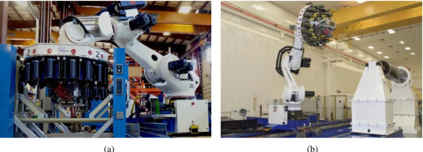
Electroimpact (USA) developed a modular placement head that can be mounted on the robot flange, it avoids using the long tow tube back to the refrigerated “creel house” attached to a major structural element mounted on a linear axis (Flynn et al., 2011, Rower, 2010, Rudberg et al., 2011), see Figure 13a. Such architecture is also used by NASA for producing composite parts for the agency’s aeronautics and space exploration programs, see Figure 13b. Similar architecture is also launched by Automated Dynamics (USA).
(a) (b)
Figure 13 (a) Robot-based AFP system with modular head developed by Electroimpact, ©Electroimpact (b) Robot-based AFP system in the Composites Technology Center of NASA, ©NASA
Mikrosam (Macedonia) is launching a system that integrates AFP head for complex parts and ATL head for flat molds into a single robotic cell for custom development of structural composites. It allows fast transition from automated fiber placement to automated tape laying and vice versa, by simply changing the head.
Current challenges still exist in design of robot based AFP, although such robotic systems have been widely employed in practice with good flexibility and adaptability. The main challenges can be related to several following terms:
Improvement of the fiber feeding system. There are two representative designs of the fiber feeding system. 1) A “creel house” is situated at the foot of the robot and pipes individually feed each fiber from the creel to the head. It is developed by Coriolis Composite, see Figure 12b. 2) A modular head is made by embedding all the fiber creels into the head. This design is delivered by Electroimpact, see Figure 13a. For the former, feeding fibers from the creel to the head limits the robot movements; and in the latter case, the increased head dimension and weight by modular designing require to use heavy payload robot (relatively slower and less accurate) (Gallet-Hamlyn, 2011). The design of feeding system might be future optimized.
Automation of robot programming. Productivity improvement can be expected from improved robot programming (Dirk et al., 2012). Since the robotic system usually contains two external axes of motion from rotational positioner and linear rail track, the system is kinematically redundant with respect to the fiber placement task. These two redundancies create some difficulties and complicate the robot programming, but it also gives some space for optimizing the robot and positioner movement to improve the productivity, for example, generating of the fastest trajectory by using the redundant degrees of freedom.
In the thesis, the challenge of productivity improvement via generating time-optimal motion at the stages of manufacturing process planning is mainly concerned and the problem of utilizing the redundant motion axes in best way is solved by generating the fastest lay-up motion for the redundant robotic system.
1.2 REDUNDANCY RESOLUTION IN ROBOTIC SYSTEMS
In order to analyze the redundancy problem, let us model the redundant robotic system with a set of links connected by rotational/translational joints. The configurations of joints are described by single scalar angle values. The complete configuration of the robotic system is specified by 8×1 vector
[ , , ]T L P R q q
q q where qL describes the configuration coordinate of the linear rail track; qP describes the
joint coordinate of the positioner; T R(q1,q2,q3,q4,q5,q6)
q describes the angles of the robot joints. A 6-dimensional lay-up task location can be described as 6×1 vector χ[x,y,z,,,]T, where (x,y,z)T is the position coordinate relative to the world frame and (,,)T is the Z-Y-X Euler angles representing the orientation. Thus, a specific posture of the end-effector can be represented in two ways, i.e. q from joint space and χ from task space.
The direct kinematic transformation is the mapping from the joint space to the task space. A point in joint space represents a unique location of the end-effector referred to the robot base frame in task space. The task kinematics can be described by χ g (q) where g() is the geometric transformation function. The standard Denavit-Hartenberg (DH) technique can be used to build the geometric model