HAL Id: hal-03049594
https://hal.archives-ouvertes.fr/hal-03049594
Submitted on 11 Dec 2020
HAL is a multi-disciplinary open access
archive for the deposit and dissemination of
sci-entific research documents, whether they are
pub-lished or not. The documents may come from
teaching and research institutions in France or
abroad, or from public or private research centers.
L’archive ouverte pluridisciplinaire HAL, est
destinée au dépôt et à la diffusion de documents
scientifiques de niveau recherche, publiés ou non,
émanant des établissements d’enseignement et de
recherche français ou étrangers, des laboratoires
publics ou privés.
Chromium valence change in trivalent chromium
conversion coatings on aluminium deposited under
applied potentials
Jiantao Qi, Jolanta Swiatowska, Peter Skeldon, Philippe Marcus
To cite this version:
Jiantao Qi, Jolanta Swiatowska, Peter Skeldon, Philippe Marcus. Chromium valence change in
triva-lent chromium conversion coatings on aluminium deposited under applied potentials. Corrosion
Sci-ence, Elsevier, 2020, 167, pp.108482. �10.1016/j.corsci.2020.108482�. �hal-03049594�
Short Communication
Chromium valence change in trivalent chromium conversion coatings on
aluminium deposited under applied potentials
Jiantao Qi
a,c,*
, Jolanta
Światowska
b, Peter Skeldon
c, Philippe Marcus
baCollege of New Energy, China University of Petroleum (East China), Qingdao, 266580, PR China
bPSL Research University, Chimie ParisTech– CNRS, Institut de Recherche de Chimie Paris, 11 Rue Pierre et Marie Curie, 75005, Paris, France cCorrosion and Protection Center, The University of Manchester, Manchester, M13 9PL, United Kingdom
A R T I C L E I N F O Keywords: Trivalent chromium Hexavalent chromium Conversion coating Hydrogen peroxide Oxygen reduction A B S T R A C T
The electroassisted (EA) deposition of trivalent chromium conversion coatings on aluminium is investigated with a focus on the influence of applied potential on the chromium valence state, as determined by Raman spec-troscopy. The morphology and compositions of the coatings were investigated by scanning electron microscopy and energy-dispersive spectroscopy. The EA coatings were formed in naturally-oxygenated SurTec 650 chromitAl solution at constant potentials of−1.5 and −0.5 VSCE. The coatings contained chromium and
zir-conium constituents. The potentials resulted in net cathodic and anodic current densities, respectively, during the coating growth. Comparisons were made with coating formation at the open-circuit potential (OCP). The coating thickness increased in order−0.5 VSCE< OCP <−1.5 VSCE, a result of increasing alkalinity from the
cathodic reaction that facilitates deposition of the coating constituents. Fresh coatings formed at−1.5 VSCE
revealed the presence of Cr6+species. By contrast, Cr6+species were not resolved in the coating formed at
−0.5 VSCE. It is proposed that less H2O2is generated at−0.5 VSCEto oxidize Cr3+coating species.
1. Introduction
Trivalent chromium conversion (TCC) coating treatments are re-garded as eco-friendly replacements of toxic chromate conversion coating processes [1–4]. A typical trivalent bath may contain hexa-fluorozirconate, trivalent chromium sulphate and supplemental in-gredients such asfluoride species [5,6]. Thefluoride component can activate the surface by thinning the surface oxidefilm to promote the coating formation [7]. The resultant coatings on aluminium and alu-minium alloys display a two-layer coating structure, consisting of an outer Zr-/Cr-rich layer over an alumina-rich layer containingfluorine species [8–11]. However, hexavalent chromium (chromate) species have been identified by Raman spectroscopy in freshly-formed coatings on aluminium [9,12]. It has been shown that the trivalent chromium can be oxidized by hydrogen peroxide generated by oxygen reduction with a 2e pathway [9,13].
Li et al. [14] evidenced chromate species preferentially formed near copper-rich particles in a TCC coated AA2024 alloy, while remaining undetectable on the particle-free matrix. This correlated with the cat-alytic role of the cathodic particles in H2O2formation and with the locally enhanced cathodic reactions during conversion treatment. Fur-thermore, more chromate was recorded on terraces near copper-rich
particles during immersion in sodium sulphate solution with a small H2O2addition (0.01 v/v) compared with the absence of H2O2, con-firming the effectiveness of H2O2as an oxidant of Cr3+species. Other work correlated H2O2 generation with colorimetric measurements using the titanly reagent and revealed thatfluoride in the reaction so-lution significantly increased H2O2formation [13].
Notably, Cr6+species were detected on TCC coated AA2024 alloy after the coating was aged in air for more than 1 h but were un-detectable in freshly-formed coatings, which was attributed to in-sufficient dissolved oxygen in the bath [7,14]. However, a chromate component was found in freshly-formed coatings on aluminium [9]. Of possible significance to this discrepancy, the steady open-circuit po-tential (OCPs) during conversion treatments of AA2024 alloy is posi-tively shifted (to−0.8 VSCE) compared with aluminium (−1.5 VSCE) [9,15], suggesting that reduction of oxygen to form hydrogen peroxide rather than hydroxyl ions may depend on the potential. With respect to electroassisted (EA) deposition of TCC coating formation, Dong et al. reported coatings containing zirconium and trivalent chromium oxides, similar to coatings formed under the open-circuit potential [8,16].
The influence of the electrochemical potential of the substrate on the formation of H2O2 and Cr6+ species during coating growth on aluminium is the focus of the present research. This factor has received
⁎Corresponding author at: College of New Energy, China University of Petroleum (East China), Qingdao, 266580, PR China.
E-mail address: jiantao.qi@upc.edu.cn(J. Qi).
https://doi.org/10.1016/j.corsci.2020.108482
little previous attention. The study specifically investigated the role of constant applied potentials of −0.5 VSCEand−1.5 VSCEduring con-version treatments in a commercial TCC solution. These potentials re-sult in net anodic and cathodic polarization of the aluminium, respec-tively. Scanning electron microscopy (SEM) with energy-dispersive X-ray spectroscopy (EDS) was used to characterize the coatings. Additionally, the coated specimens were analysed by Raman spectro-scopy to determine the chromium chemistry and its dependence on the applied potential and immersion time.
2. Experimental procedure 2.1. Materials and regnant
Specimens, of dimensions 30 × 12 × 0.3 mm, were cut from 99.97 % aluminium sheet, rinsed sequentially in acetone, ethanol and deio-nized water, then electropolished in a mixture of perchloric acid and ethanol (1:4 volumes) at 20 V for 240 s below 10 °C. They were then rinsed in ethanol and deionized water and dried in a stream of cool air. SurTec 650 chromitAL (SurTec Corp.) was diluted with deionized water at a volume ratio of 1:4 and then 1 wt.% NaOH droplets were used to adjust the solution pH to 3.9. Inductively coupled plasma-atomic emission spectroscopy (ICP-AES) analysis of the bath, using a Perkin-Elmer Optima 5300 dual view instrument, revealed a Zr/Cr atomic ratio of 0.70 ± 0.02. The composition of SurTec 650 chromitAL is subject to commercial confidentiality, but is presumed to contain zirconium hexafluorozirconate, tri-valent chromium sulphate and fluoride constituents that are usually present in TCC baths. Consistent with the presence of such constituents, other work has shown that ZrO2, Cr(OH)s, CrF3 and Cr2(SO4)3 are principal components of coatings formed in SurTec 650 chromitAL solution [9].
A three-electrode cell, containing a saturated calomel electrode (Eº = 0.24 V vs NHE), a graphite cathode and a specimen with an ex-posed area of∼2.25 cm2, was used for coating formation. Potentials were controlled by a Solarton electrochemical workstation with a Modulab software controller. First a potential of +0.5 VSCEwas applied for 10 s to activate the surface and then the potential was increased to −0.5 or −1.5 VSCEfor either 1200 or 2400s. The time of the coating process was selected to be the same as (1200s) or greater than (2400s) the time used in previous work that revealed chromate species in a coating formed under the OCP condition [9,13]. The coated specimens were immediately removed from the cell and examined by Raman spectroscopy within 10 s to limit the possibility of oxidation of Cr3+ species in air. In addition, potentiodynamic polarization of electro-polished aluminium was performed from−2 to 0 VSCEat 1 mV/s in the SurTec 650 chromitAL solution (40 °C, pH 3.9). The specimen wasfirst polarized at +0.5 VSCEand then the potential was immediately swit-ched to−2.0 VSCEfor the start of the potential scan. The experiments were repeated three times, revealing reproducible polarization beha-viour.
2.2. Characterization methods
SEM-EDS employed a Zeiss Ultra 55 instrument at accelerating voltages of 3 and 15 kV. Raman spectroscopy used a Renishaw 2000 Raman instrument with an argon laser (wavelength 514 nm, 12.5 mW power). Calibration utilized a silicon peak at 520 cm−1in the static mode. For specimen examination, the extended mode from 1200 to 200 cm−1was employed with 30 s integration and 10-time accumula-tion to eliminate any background noise effect.
3. Results and discussion
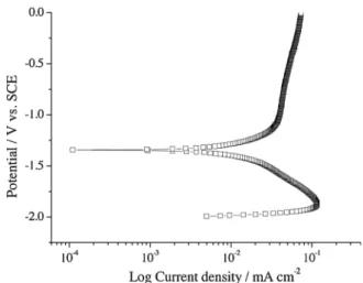
Fig. 1presents the polarization curve for electropolished aluminium in SurTec 650 solution (40 °C, pH 3.9) scanned from−2.0 VSCEto 0 VSCE. The current density in the cathodic branch rises to a peak value of
1.02 × 10⁻⁴A cm−2 at−1.85 VSCEthen decreases with a log-linear dependence on voltage over almost one decade of current density be-fore decreasing steeply to zero net current density at−1.34 VSCE. The latter value compares with OCPs in the range−1.54 to −1.50 VSCE reported previously for growth of a coating over a period of 1200s in the same solution. The lower potential of zero current density in the polarization curve is due to the influence of the prior period of cathodic polarization. The decline in the magnitude of the cathodic current at potentials below−1.85 VSCEcan be attributed to the contribution of an anodic current density due to activation of the aluminium substrate. The net cathodic current density at higher potentials, which arises from reduction of H+ions, water molecules and dissolved oxygen, exceeds the anodic current density due to oxidation of aluminium. The current density in the anodic branch of the polarization curve rise steeply until a potential of about−1.00 VSCE, when the slope decreases sharply and the current density then rises slowly from 4 × 10⁻⁵A cm−2to about 7 × 10⁻⁵A cm−2at 0.0 VSCE.
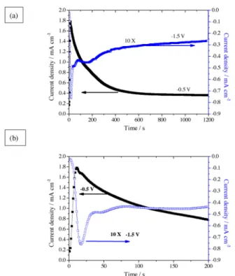
Coatings were prepared under constant potentials of −1.5 and −0.5 VSCE. At−1.5 VSCE, reduction of H+ions and dissolved oxygen can contribute to the cathodic current density. Oxygen reduction may be dominant at−0.5 VSCEas the equilibrium potential for H+reduction is close to−0.5 VSCEat the pH of the bulk solution (3.9). The former potential is close to the OCP potential for coatings formed by simple immersion in the naturally aerated solution. The current density during coating treatments for times of 1200s are shown inFig. 2(a). The details of thefirst 200 s of treatment are shown inFig. 2(b). For the treatment at−1.5 VSCE, the main features of the curve are an (i) increase in the net cathodic current density to−0.75 mA cm−2in the first 20 s of polarization followed by a fall to −0.50 mA cm−2after 30 s; (ii) a plateau at −0.45 mA cm−2 between 75–200 s; (iii) a decrease at a progressively reducing to afinal current density of −0.26 mA cm−2. Thus, the specimen was cathodically polarized over the whole of the treatment time. The polarization at−0.5 VSCEresulted in a net anodic current density throughout the coating process, comprising an initial rapid rise in current density to 1.8 mA cm−2 during the initial 20 s followed by a smooth decrease at a reducing rate to reach afinal value of 0.4 mA cm−2. Notably, the current density in the potentiodynamic polarization curve at−0.5 VSCE, namely 0.03 mA cm−2, is lower than thefinal value of the potentiostatic curve (0.4 mA cm−2). It is due to the much greater coating thickness that results from the prior cathodic polarization of the specimen at the start of the polarization scan. The strong influence of cathodic polarization on the coating thickness is evident in the results from EDS analyses presented later. In addition, the curves for both−1.5 and −0.5 VSCEshows rapid increases in the cur-rent density in the first 20 s of polarization. This is probably due to thinning of the oxide film that was present on the surface of the
Fig. 1. Potentiodynamic polarization curve of electropolished aluminium during immersion in SurTec 650 chromitAL solution (40 °C, pH 3.9) for 2000s. J. Qi, et al.
electropolished aluminium specimens. Thereafter, growth of the coating causes the net anodic and cathodic current densities to de-crease.
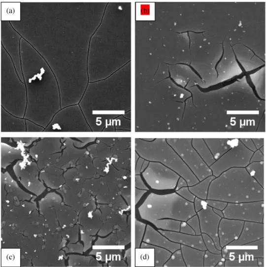
Fig. 3(a–d) presents scanning electron micrographs of TCC coatings
formed at the OCP (≈−1.45 VSCE) for 1200s,−0.5 VSCEfor 1200 and 2400s and at−1.5 VSCEfor 1200s. A smooth coating surface resulted in most regions of all coatings. However, the coatings contained cracks generated by dehydration and shrinkage of the coating material during drying. The coatings also contained deposits of solution precipitates [14], which are evident as granular features of white appearance at the coating surface. The cracks in the coatings formed at the OCP and −1.5 VSCEfor 1200s formed a continuous network. In contrast, cracks in the coating formed at−0.5 VSCE, often propagated short distances from the points of initiation and did not connect with other cracks. This difference in the crack morphology is possibly related to differing de-grees of hydration of the coating material, and hence in the magnitude of the stresses caused by shrinkage of the coating, and also to differing coating thicknesses. The cracking, which has been reported previously in similar coatings [9,17], is likely to have been exacerbated by ex-posure to vacuum of the microscope.
Fig. 4shows results of EDS spot analyses made at an accelerating voltage of 15 kV on the surface of coatings formed at the OCP (−1.45 VSCE),−0.5 and −1.5 VSCEfor 1200s. The analyses were made remote from locations of cracks. A coating was also formed for 2400s at −0.5 VSCE. After coating formation, the specimens were immersed in deionized water for 120 s and dried in a cool-air stream. The spectra contain peaks from oxygen, aluminium,fluorine, zirconium and chro-mium in the coating and of carbon from adsorbed contaminant. Ac-cording to previous X-ray photoelectron spectroscopy, ZrO2, Cr(OH)s, CrF3and Cr2(SO4)3are the main constituents of the outer layer of the coating [9]. Insufficient sulphur was present in the coating for the
sulphur Kα peak at 2.307 keV to be clearly resolved in the spectra
Fig. 4. The additional, much higher peak in the spectra originating from aluminium mainly results from X-ray generation from the aluminium substrate that dominates the contribution from aluminium in the inner alumina-rich layer of the coating, which also contains a significant
amount of fluorine [9,18]. The SurTec solution contains hydrolysed trivalent chromium and zirconium species [13,19], which form deposits of the coating material on the aluminium surface as a result of the in-creases in pH that results from the reduction of H+ions and dissolved oxygen [8,16]. The highest peaks forfluorine, zirconium and chromium were associated with the cathodically polarized specimen coated at −1.5 VSCE for 1200s. The lowest peaks occurred for the anodically polarized specimen coated at−0.5 VSCEfor 1200s. The peaks for the coating formed at the OCP for 1200s were between those of the pre-vious coatings. Taking the height of the zirconium peak as an indicator of the coating thickness, the cathodically polarized aluminium was about 2.5 times thicker than that on the specimens coated at the OCP and about 6 times thicker than the coating formed at−0.5 VSCE. The EDS results indicate the significant increase in the rate of coating growth that can be achieved by reducing potential below the OCP. In contrast, the rate of growth is significantly lowered at potentials above the OCP. In the present instance, the rate of growth of the coating formed at−0.5 VSCEwas about 2.5 times slower than at the OCP. The coating thickness of the anodically polarized specimen was increased by about a factor of two by doubling the treatment time from 1200s to 2400s [15].
Fig. 5shows Raman spectra of the coated specimens treated for
1200s at the OCP,−1.5 V and −0.5 V vs SCE. In all spectra, zirconium oxide was identified by peaks at 470 and 537 cm−1and chromium sulphate at 998 cm−1. The peak around 810 cm−1is associated with aluminium hydroxides [6]. The spectra for coatings formed at −1.5 VSCEand the OCP had an additional peak for Cr6+ species at 866 cm−1. This peak was not resolved at −0.5 V even when the treatment was extended to 2400s. After this time of treatment, the EDS analyses showed that the coating thickness was similar to that of the coating formed at the OCP. This difference in the spectra indicates the much greater presence of Cr6+species in the coatings formed at the more negative potentials. The chromate species result from the oxida-tion of Cr3+species by the H2O2generated by oxygen reduction, which can occur by two pathways:
O2+ 2H++ 2e−→ H2O2(Eº = +0.44 V vs. SCE) (1) O2+ 4H++ 4e−→ 2H2O (Eº = +0.99 V vs. SCE) (2) The relative contributions of Reactions(1)and(2)to the overall oxygen reduction current on the present specimens is unknown, but is likely to depend upon the coating composition, the presence of ad-sorbed species, the solution pH adjacent to the specimen surface and the electrode potential [17]. For instance, the oxygen reduction current due to Reaction (1) has been shown to depend upon the substrate composition and to increase at more cathodic potentials [17]. Cathodic polarization of aluminium can also encourage the formation of hy-drogen peroxide from reaction of hydroperoxyl radicals, as follows [20],
(O2)ads+ H++ e→ HO2%(pH < 4.8) (3) HO2%+ HO2%→ H2O2+ O2 (4) Cr3+oxidation in TCC coatings can be mitigated using an addition to the bath that can be preferentially oxidized by H2O2. Xia et al. [21] reported the effectiveness of IrCl6−3/−2, Fe+3/+2, V+3/+2and Fe(CN)6 -3/-4
. For instance, the standard potentials of IrCl6−3/−2and Cr6+/Cr3+ are +1.02 and +1.33 VNHErespectively, and the Gibbs free energy of the IrCl6−3/−2 redox system is lower than that of chromium system. Thus, IrCl6−3/−2can be preferentially oxidized by H2O2. Our previous work employed Fe+3/+2additions to the SurTec solutions to restrict Cr6+formation in freshly-formed TCC coatings on AA2024 alloy [22]. 4. Conclusions
1 The present work, focused on the influence of applied potential on
Fig. 2. (a) Current transients obtained during potentiostatic polarization of aluminium in SurTec 650 chromitAL solution (40 °C, pH 3.9) at −0.5 and −1.5 VSCEfor 1200s. (b) Detail of the initial 200 s.
J. Qi, et al.
the chromium valence state in freshly-formed coatings on alumi-nium, provides new insights into the effect of the potential on the coating morphology and the formation of Cr6+species. Cathodic polarization at−1.5 VSCEled to a coating about 2.5 times thicker than one formed at the OCP and about 6 times thicker than the one formed under anodic polarization (−0.5 VSCE). The thickening of the coating is due to enhanced by increasing polarization of the
cathodic reaction that increases the local pH at the coating surface. 2 Raman spectroscopy revealed Cr6+ species in a coating freshly-formed under cathodic polarization at of−1.5 VSCE. However, such species were not detectable in a coating formed at−0.5 VSCE. The latter is attributed to reduced generation of H2O2 by the oxygen reduction reaction and hence reduced availability of H2O2to oxidize
Fig. 3. Scanning electron micrographs of TCC coatings formed at the (a) OCP for 1200s, (b)−0.5 VSCEfor 1200s, (c)−0.5 VSCEfor 2400s and (c)−1.5 VSCEfor
1200s.
Fig. 4. SEM/EDS spectra forfluoride, zirconium and chromium components in coatings formed on aluminium in SurTec 650 chromitAL solution (40 °C, pH 3.9) at the OCP and−0.5 and −1.5 VSCEfor 1200s and−0.5 VSCEfor 2400s.
Fig. 5. Raman spectra of coatings formed on aluminium in SurTec 650 chromitAL solution (40 °C, pH 3.9) at the OCP and−0.5 and −1.5 VSCEfor
1200s and−0.5 VSCEfor 2400s.
J. Qi, et al.
Cr3+species. Author statement
Jiantao Qi carried out the data curation and writing-Original draft preparation; JolantaŚwiatowska provided the Raman methodology and validation; Peter Skeldon carried out the investigation, reviewing and editing; Philippe Marcus carried out the paper writing - reviewing and editing. All authors contributed to the interpretation of the results and to the writing of the paper.
Declaration of Competing Interest
The authors declare that they have no known competingfinancial interests or personal relationships that could have appeared to influ-ence the work reported in this paper.
Acknowledgements
The authors thank the National Natural Science Fund (51701239), Shandong Natural Science Fund (ZR2017LEM005) Fundamental Research Funds for the Central Universities (18CX02128A) and the LATEST2 Programme Grant (EP/H020047/1) for thefinancial support of this work.
References
[1] M.W. Kendig, R.G. Buchheit, Corrosion inhibition of aluminum and aluminum al-loys by soluble chromates, chromate coatings, and chromate-free coatings, Corrosion 59 (2003) 379–400,https://doi.org/10.5006/1.3277570.
[2] D.B. Mitton, A. Carangelo, A. Acquesta, T. Monetta, M. Curioni, F. Bellucci, Selected Cr(VI) replacement options for aluminum alloys: a literature survey, Corros. Rev. 35 (2017) 365–381,https://doi.org/10.1515/corrrev-2016-0059.
[3] M. Ely, J.Światowska, A. Seyeux, S. Zanna, P. Marcus, Role of post-treatment in improved corrosion behavior of trivalent chromium protection (TCP) coating de-posited on aluminum alloy 2024-T3, J. Electrochem. Soc. 164 (2017) C276–C284,
https://doi.org/10.1149/2.0431706jes.
[4] X. Verdalet-Guardiola, B. Fori, J.-P. Bonino, S. Duluard, C. Blanc, Nucleation and growth mechanisms of trivalent chromium conversion coatings on 2024-T3 alu-minium alloy, Corros. Sci. 155 (2019) 109–120,https://doi.org/10.1016/j.corsci. 2019.04.035.
[5] Y. Guo, G.S. Frankel, Characterization of trivalent chromium process coating on AA2024-T3, Surf. Coat. Technol. 206 (2012) 3895–3902,https://doi.org/10.1016/ j.surfcoat.2012.03.046.
[6] C.A. Munson, S.A. McFall-Boegeman, G.M. Swain, Cross comparison of TCP con-version coating performance on aluminum alloys during neutral salt-spray and thin-layer mist accelerated degradation testing, Electrochim. Acta 282 (2018) 171–184,
https://doi.org/10.1016/j.electacta.2018.04.115.
[7] L.L. Li, G.P. Swain, A. Howell, D. Woodbury, G.M. Swain, The formation, structure, electrochemical properties and stability of trivalent chrome process (TCP) coatings on AA2024, J. Electrochem. Soc. 158 (2011) C274–C283,https://doi.org/10.1149/ 1.3607980.
[8] X.C. Dong, P. Wang, S. Argekar, D.W. Schaefer, Structure and composition of tri-valent chromium process (TCP)films on Al alloy, Langmuir 26 (2010) 10833–10841,https://doi.org/10.1021/la100699u.
[9] J.T. Qi, T. Hashimoto, J.R. Walton, X. Zhou, P. Skeldon, G.E. Thompson, Trivalent chromium conversion coating formation on aluminium, Surf. Coat. Technol. 280 (2015) 317–329,https://doi.org/10.1016/j.surfcoat.2015.09.024.
[10] C.A. Munson, G.M. Swain, Structure and chemical composition of different variants of a commercial trivalent chromium process (TCP) coating on aluminum alloy 7075-T6, Surf. Coat. Technol. 315 (2017) 150–162,https://doi.org/10.1016/j. surfcoat.2017.02.018.
[11] R. Viroulaud, J.Światowska, A. Seyeux, S. Zanna, J. Tardelli, P. Marcus, Influence of surface pretreatments on the quality of trivalent chromium process coatings on aluminum alloy, Appl. Surf. Sci. 423 (2017) 927–938,https://doi.org/10.1016/j. apsusc.2017.06.246.
[12] J. Qi, J. Walton, G.E. Thompson, S.P. Albu, J. Carr, Spectroscopic studies of chro-mium VI formed in the trivalent chrochro-mium conversion coatings on aluminum, J. Electrochem. Soc. 163 (2016) C357–C363,https://doi.org/10.1149/2.0531607jes. [13] J. Qi, L. Gao, Y. Liu, B. Liu, T. Hashimoto, Z. Wang, G.E. Thompson, Chromate
formed in a trivalent chromium conversion coating on aluminum, J. Electrochem. Soc. 164 (2017) C442–C449,https://doi.org/10.1149/2.0021709jes.
[14] L.L. Li, D.Y. Kim, G.M. Swain, Transient formation of chromate in trivalent chro-mium process (TCP) coatings on AA2024 as probed by Raman spectroscopy, J. Electrochem. Soc. 159 (2012) C326–C333,https://doi.org/10.1149/2.019208jes. [15] J. Qi, T. Hashimoto, J. Walton, X. Zhou, P. Skeldon, G.E. Thompson, Formation of a
trivalent chromium conversion coating on AA2024-T351 alloy, J. Electrochem. Soc. 163 (2016) C25–C35,https://doi.org/10.1149/2.0771602jes.
[16] X.C. Dong, S. Argekar, P. Wang, D.W. Schaefer, In situ evolution of trivalent chromium process passivefilm on Al in a corrosive aqueous environment, ACS Appl. Mater. Interfaces 3 (2011) 4206–4214,https://doi.org/10.1021/am200845v. [17] J. Qi, G. Thompson, Comparative studies of thinfilm growth on aluminium by AFM, TEM and GDOES characterization, Appl. Surf. Sci. 377 (2016) 109–120,https://doi. org/10.1016/j.apsusc.2016.03.115.
[18] J. Qi, T. Hashimoto, G.E. Thompson, J. Carr, Influence of water immersion post-treatment parameters on trivalent chromium conversion coatings formed on AA2024-T351 alloy, J. Electrochem. Soc. 163 (2016) C131–C138,https://doi.org/ 10.1149/2.0221605jes.
[19] D. Chidambaram, C.R. Clayton, G.P. Halada, The role of hexafluorozirconate in the formation of chromate conversion coatings on aluminum alloys, Electrochim. Acta 51 (2006) 2862–2871,https://doi.org/10.1016/j.electacta.2005.08.022. [20] S.H. Joo, A.J. Feitz, T.D. Waite, Oxidative degradation of the carbothioate
herbi-cide, molinate, using nanoscale zero-valent iron, Environ. Sci. Technol. 38 (2004) 2242–2247,https://doi.org/10.1021/es035157g.
[21] L. Xia, R.L. McCreery, Structure and function of ferricyanide in the formation of chromate conversion coatings on aluminum aircraft alloy, J. Electrochem. Soc. 146 (1999) 3696–3701,https://doi.org/10.1149/1.1392536.
[22] J. Qi, B. Zhang, Z. Wang, Y. Li, P. Skeldon, G.E. Thompson, Effect of an Fe(II)-modified trivalent chromium conversion process on Cr(VI) formation during coating of AA 2024 alloy, Electrochem. Commun. 92 (2018) 1–4,https://doi.org/ 10.1016/j.elecom.2018.05.013.
J. Qi, et al.