Revealing MPLS Tunnels Obscured from Traceroute
Benoit Donnet
Matthew Luckie
Pascal Mérindol, Jean-Jacques Pansiot
Université de Liège CAIDA / UC San Diego Université de Strasbourg
Belgium USA France
[email protected]
[email protected]
{merindol,jean-jacques.pansiot}@unistra.fr
ABSTRACT
Operators have deployed Multiprotocol Label Switching (MPLS) in the Internet for over a decade. However, its im-pact on Internet topology measurements is not well known, and it is possible for some MPLS configurations to lead to false router-level links in maps derived from traceroute data. In this paper, we introduce a measurement-based classifica-tion of MPLS tunnels, identifying tunnels where IP hops are revealed but not explicitly tagged as label switching routers, as well as tunnels that obscure the underlying path. Us-ing a large-scale dataset we collected, we show that paths frequently cross MPLS tunnels in today’s Internet: in our data, at least 30% of the paths we tested traverse an MPLS tunnel. We also propose and evaluate several methods to reveal MPLS tunnels that are not explicitly flagged as such: we discover that their fraction is significant (up to half the explicit tunnel quantity) but most of them do not obscure IP-level topology discovery.
Categories and Subject Descriptors
C.2.1 [Network Architecture and Design]: Network Topology
General Terms
Measurement
Keywords
taxonomy, traceroute, MPLS, topology
1.
INTRODUCTION
Multiprotocol Label Switching(MPLS) [1] was designed to reduce the time required to make forwarding decisions. It is now deployed to provide additional virtual private network (VPN) services [2] and traffic engineering capability [3, 4]. To accomplish this, an IP router inserts one or more 32-bit label stack entries(LSE) into a packet, before the IP header, that determines the forwarding actions made by subsequent MPLS Label Switching Routers (LSRs) in the network. A se-ries of LSRs connected together form a Label Switched Path (LSP). MPLS networks are deployed on IP routers that use a label distribution protocol [5, 6].
In an MPLS network, packets are forwarded using an ex-act match lookup of a 20-bit label found in the LSE. An MPLS LSE also has a time-to-live (LSE-TTL) field and a type-of-service field. At each MPLS hop, the label of the in-coming packet is replaced by a corresponding outgoing label
found in an MPLS switching table. The MPLS forwarding engine is lighter than the IP forwarding engine because find-ing an exact match for a label is simpler than findfind-ing the longest matching prefix for an IP address.
MPLS routers may send ICMP time-exceeded messages when the LSE-TTL expires. In order to debug networks where MPLS is deployed, routers may also implement RFC 4950 [7], an extension to ICMP that allows a router to em-bed an MPLS label stack in an ICMP time-exceeded mes-sage. The router simply quotes the MPLS label stack of the probe in the ICMP time-exceeded message. RFC4950 is particularly useful to operators as it allows them to verify the correctness of their MPLS tunnels and traffic engineer-ing policy. This extension mechanism has been implemented by router manufacturers since 1999 [8], and is displayed by modified versions of traceroute [9] that report the label stack returned by each hop in addition to RTT values currently displayed. If the first MPLS router of an LSP (the Ingress Label Edge Router - LER) copies the IP-TTL value to the LSE-TTL field rather than setting the LSE-TTL to an ar-bitrary value such as 255, LSRs along the LSP will reveal themselves via ICMP messages even if they do not imple-ment RFC4950. Operators configure this action using the ttl-propagateoption provided by the router manufacturer. These two “MPLS transparency” features – RFC 4950 functionality and the ttl-propagate option – increase the observability of otherwise opaque MPLS tunnels during IP-level topology discovery based on traceroute. Unfortunately, lack of universal deployment of these two features (ingress LERs that do not enable the ttl-propagate option, and LSRs that do not support the RFC4950 ICMP extensions) means that current traceroute-based inference methods can cause false router-level links to be inferred and underesti-mates MPLS deployment in the Internet.
In this paper, we develop and evaluate new inference meth-ods to reduce the errors induced by MPLS tunnels on IP-level topology discovery, by identifying their presence in the forwarding path even in the face of incomplete deployment of these two features. Section 2 presents a taxonomy of MPLS tunnel configurations and how they appear in traceroute output. Our taxonomy is conceptually a 2x2 matrix of the two MPLS transparency features. Section 3 positions our work amongst the current state of the art. In section 4 we describe our measurement experiment designed to quantify the extent of MPLS tunnels obscured from traceroute. Our experimental results in section 5 indicate that MPLS tun-nels are common in today’s Internet; from 75 vantage points to every routed BGP prefix at least 30% of traceroutes
tra-R1 R2 R3 R4 R5 Monitor Destination LSP 1. R1 2. R2 3. R3 4. R4 5. R5 6. Destination 1. R1 2. R2- MPLS 3. R3- MPLS 4. R4- MPLS 5. R5 6. Destination 1. R1 2. R4- MPLS 3. R5 4. Destination 1. R1 2. R4 3. R5 4. Destination Implicit
Explicit Opaque Invisible
IH LH
Ingress LER
Egress LER
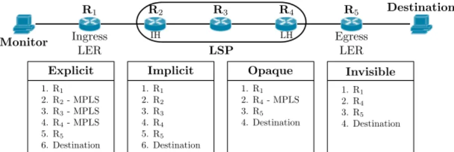
Figure 1: Taxonomy of MPLS tunnel configurations and corresponding traceroute behaviours. LSRs in implicit tunnels do not explicitly reveal the use of MPLS. Opaque and invisible tunnels hide LSRs and contribute to false router-level links.
versed at least one explicit MPLS tunnel. Section 6 evalu-ates two complementary tunnel fingerprinting methods: one based on the quoted IP TTL in ICMP time-exceeded mes-sages, and the other on the IP TTL returned by suspected LSRs in ICMP echo reply messages. Section 7 estimates the number of IP links missed and misinterpreted due to MPLS tunnels that do not activate the ttl-propagate option. Fi-nally, section 8 concludes the paper by summarising its main achievements and discusses directions for future work.
2.
MPLS TUNNEL TAXONOMY
The absence or presence of the two MPLS transparency features frame our taxonomy of four classes of MPLS tun-nels. Figure 1 illustrates the four classes. In all cases, router R1 is the entry of the MPLS tunnel and is the first router
to push an MPLS label; we call this router the ingress LER. Router R2 is the first LSR where the incoming packet
in-cludes a LSE; we call this router the ingress hop (IH). The IH is the first LSR where RFC4950 applies and the first ex-plicitly labeled hop. In figure 1 router R4 is the last router
that pops the MPLS label; we call this router the last hop (LH). At least for Cisco routers, the LH router is located one hop before the egress LER due to the use of penultimate hop popping(PHP) [1, 10]. In this case, the last MPLS hop is implicit because the packet does not need to carry any LSE. Therefore, our four tunnel categories are:
• explicit tunnels: both ttl-propagate and RFC4950 are enabled. The tunnel and its internal structure are visible. Each hop within the LSP is flagged as such (as illustrated with “MPLS” in figure 1).
• implicittunnels: the ingress LER enables the ttl-propagate option but LSRs do not implement RFC4950. In this case, while the internal IP structure of the tunnel is vis-ible, its existence as an MPLS tunnel is not revealed. As illustrated in figure 1, the traceroute output of a path containing an implicit tunnel is equivalent to a trace without any MPLS indication.
• opaque tunnels: LSRs implement RFC4950 but the ingress LER does not enable the ttl-propagate op-tion. Only the LH of the LSP reveals a LSE and the internal structure of the LSP is hidden. In figure 1, the opaque tunnel hides two LSRs (R2 and R3), allowing
an erroneous link to be inferred between R1 and R4.
• invisible tunnels: the ingress LER does not enable the ttl-propagate option and RFC4950 is not im-plemented by the LH router. In figure 1, two IP hops
are hidden and the LH router does not flag itself as part of an LSP. Again, a link between R1 and R4 is
erroneously inferred.
Only explicit tunnels are directly interpretable from trace-route output. The other categories require additional pro-cessing and/or active probing to interpret. In this paper, we propose methods to identify implicit and opaque tunnels.
3.
RELATED WORK
Sommers et al. recently examined the characteristics of MPLS deployments that are explicitly identified using RFC-4950 extensions, as observed in CAIDA’s topology data [11]. In this data, they found explicit tunnels in 7% of ASes, and the fraction was constant over three years of data; how-ever, the total number of explicit MPLS tunnels varied over time. They also developed a methodology to infer MPLS tunnels in archived data where ICMP extensions are not recorded. CAIDA’s topology data began recording ICMP extensions in May 2008; to enable MPLS deployment trends to be analysed prior to this, they implemented a passive Bayesian inference method. Their key observations are (1) interfaces in LSPs are likely to be numbered using IP ad-dresses that are close in terms of prefix length, and (2) RTTs of time-exceeded messages from all LSRs in an LSP are likely to be similar because a common MPLS configuration is for all LSRs to forward these messages to the end of the LSP for the egress router to return1
. Our studies are com-plementary; we examine the deployment of explicit tunnels, but we also develop methods to infer other configurations that cause the LSP to be obscured from traceroute. In ad-dition, because our studies are complementary our methods can be used conjointly to cross-validate each other.
Sherwood et al. investigated the presence of anonymous and hidden routers as part of DisCarte [12]. They found that 0.3% of routers in their dataset were hidden from traceroute because they did not decrement the TTL. They identified anonymous and hidden routers using the IP Record Route option; however, they note that routers involved in an MPLS LSP do not record an IP address in the IP option space provided, so the record route option is not able to identify hidden routers in opaque or invisible configurations.
1
That is, all traceroute probes through an LSP make the same round trip. However, pure IP routers may be inferred to be part of an LSP if (for example) an ASes preferred route to the source of the traceroute probes is also through the same egress point towards the destination.
10 20 30 40 50 60 70
monitor
0 .0 0 .2 0 .4 0 .6 0 .8 1 .0fr
a
ct
io
n
(a) Fraction of paths with explicit MPLS tunnels observed per monitor
0 5 10 15 20 25 30 35 40
distance (IP hops)
0 .0 0 .2 0 .4 0 .6 0 .8 1 .0
cd
f
total Minneapolis (US) London (UK) Auckland (NZ)(b) Distance of each unique explicit MPLS tunnel from each monitor
0 2 4 6 8 10
length (hops)
0 .0 0 .2 0 .4 0 .6 0 .8 1 .0cd
f
total Minneapolis (US) London (UK) Auckland (NZ)(c) Length of each unique explicit MPLS tunnel
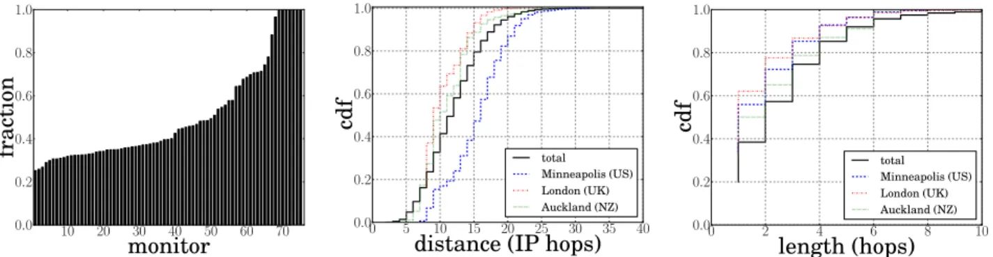
Figure 2: Characteristics of explicit tunnels. Half of the monitors in our study observe an explicit tunnel in at least 40% of paths. In our data, 95% of unique tunnels begin at least 5 IP hops away from the monitor, and 90% of tunnels are less than five hops in length.
4.
DATASET
Because only explicit tunnels are directly retrievable from traceroute output, we designed our own measurement ex-periment to study implicit and opaque tunnels. We used Paris traceroute with ICMP-echo packets [13] to collect the forward IP path, and for each interface discovered we sent ICMP-echo probes in order to infer implicit tunnels (see section 6.1). We generated target IP address lists based on prefixes found in a Route Views [14] BGP table from Au-gust 2011, probing a random address in each /16 for prefixes not enclosed in any other prefix of length 16 or shorter, and probing a random address in each other prefix of length 24 or shorter, but only one destination in any /24. We evenly di-vided each target list among a team of 25 PlanetLab vantage points (VPs). In total we used three teams (75 PlanetLab VPs) with three different target lists. Of the 75 VPs, 45 were located within the US; the other 30 VPs were located in 18 different countries. Data was collected on August 24th
, 2011 using scamper [15].
5.
EXPLICIT TUNNELS
In this section, we focus on explicit tunnels, i.e., LSPs where the ttl-propagate option is enabled at the ingress LER and whose LSRs implement RFC4950. Our goal is not to show AS-level graph statistics or other statistics provided in [11] but rather to use explicit tunnels as a basis to esti-mate MPLS tunnels obscured from traceroute.
Figure 2(a) provides, for each monitor, the fraction of traceroutes encountering at least one explicit MPLS tunnel; monitors are sorted according to their proportion of trace-routes including explicit tunnels. For seven monitors (one in France, the others in North and South America), every traceroute path traversed an MPLS tunnel since the hosting ISP used MPLS. Apart from these extreme cases, MPLS is quite prevalent in our observations. Typically, more than 30% of the paths we infer from each monitor exhibit at least one explicit MPLS tunnel. This corroborates Sommers et al.recent results [11], where they observed an MPLS tunnel in 25% of their studied paths.
Figures 2(b) and 2(c) plot characteristics of uniquely ob-served tunnels. We uniquely identify an MPLS tunnel as a list of labelled IP addresses < h0, h1, h2, . . . , hn−1, hn >,
where h0 is the IH router, hn the LH router, and hi’s are
LSRs within the LSP; we do not consider the MPLS label
for identifying tunnels as there may be a different label for each routed prefix. Counting MPLS tunnels this way yields an average of 1,200 explicit tunnels per vantage point, and a global total (i.e., the inter-monitor union of explicit tunnels) of 51,881 distinct explicit tunnels.
We also quantified MPLS deployment at an IP interface granularity by counting the number of interfaces that return an ICMP response with an RFC4950 MPLS extension, and dividing by the total number of interfaces observed. Our experiment resulted in a ratio of 21,921
385,129 ≈5.6% highlighting
that MPLS is well deployed in today’s Internet.
Our results also indicate that MPLS is more prevalent in the core of the Internet (i.e., in Tier-1 ASes) than in leaf net-works (i.e., Stub ASes). Figure 2(b) plots the distribution of IP hop distance between the PlanetLab monitors and the IH router of an explicit LSP. In more than 95% of the cases, an MPLS tunnel starts at least five IP hops from the mon-itor location. Apart from extreme cases such as the seven monitors with MPLS support within the monitor’s hosting ISP, the first tunnel is not located within the monitor’s ISP but at least one AS further in the AS topology. Our di-versity of probed destinations offers a comprehensive set of independent traces to study MPLS deployment.
Finally, figure 2(c) plots the distribution of explicit tunnel length, i.e. the number of subsequent explicitly labelled IP addresses2
. 90% tunnels are relatively short with no more than five hops. However, we encounter a 23-router tunnel in the NTELOS network. It may be an anomaly, or it may be a management LSP that purposefully crosses many nodes and links, allowing the member routers to be monitored with ping, as a single probe will cross them all.
6.
IMPLICIT TUNNELS
Implicittunnels are those that enable the ttl-propagate option but do not enable RFC4950. They provide a classic behavior when tracerouting through them; we do not miss any information at the IP level and do not derive false links because of their presence. However, LSRs within an implicit tunnel are not flagged as such and require additional probing to reveal their existence and estimate MPLS deployment.
2
Note that the RFC4950 implementation is on a per router basis, therefore an explicit tunnel may be only a subset of the actual underlying MPLS tunnel.
Ingress LER
Egress LER
push push push push
pop pop pop pop
IH LSR LH LSR
∆ u-turn: 8 ∆ u-turn: 6 ∆ u-turn: 4 ∆ u-turn: 2
LSP
q-ttl=1 q-ttl=2 q-ttl=3 q-ttl=4
ping return path traceroute return path propagate
IP→ MPLS
propagate MPLS→ IP
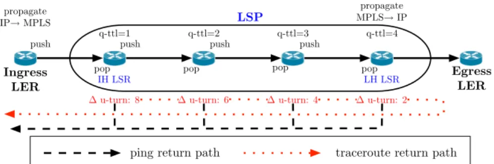
Figure 3: Detection of implicit MPLS tunnels using TTL signatures. It is the LSE-TTL that is decremented until expiry, so the quoted IP-TTL in ICMP time-exceeded messages will be > 1; we infer an implicit tunnel using signatures of increasing quoted IP-TTL values. Some LSRs send ICMP error messages via a nominated router but send ICMP echo replies directly, so the IP-TTL of these packets will be different for the same router; we infer an implicit tunnel using signatures of decreasing difference in received IP-TTLs.
0 10 20 30 40 50 60 70
monitor
0 .0 0 .2 0 .4 0 .6 0 .8 1 .0fr
a
ct
io
n
explicit signature coverage implicit
Figure 4: The fraction of explicit and implicit tun-nels as viewed by each monitor. Some monitors in-fer many more implicit tunnels, suggesting the lo-cation of each monitor can introduce measurement error. We deduce implicit tunnels are three times less prevalent than explicit tunnels.
6.1
Inference Methodology
It is possible to detect some implicit tunnels by examining the IP packet quoted in an ICMP time-exceeded reply, in particular the TTL of the probe quoted when the reply was generated. This specific TTL is called the quoted TTL. A quoted TTL > 1 is likely due to use of the ttl-propagate option at the ingress LER of an LSP. For each traceroute probe that visits a subsequent LSR within an LSP, the quoted TTL will be one greater, and we will observe an increasing sequence of quoted TTL values in traceroute. We call this fingerprint technique the q-ttl signature, and it is illustrated in figure 3. We are not able to exploit the q-ttl signature if a LSR sets the IP-TTL to the LSE-TTL (1) when the LSE-TTL expires.
However, additional ping probing can reveal what we call the MPLS u-turn tunnel signature. It relies on the fact that most LSRs in an LSP present a common behavior: when the LSE-TTL expires, the LSR first sends the time-exceeded reply to the LH router which then forwards the reply to the probing source, but the LSR sends other packets using an IP route if available. Operators can configure this behaviour using the mpls ip ttl-expiration pop command on Cisco routers. If the command is used, the IP-TTL received at each monitor from packets sent by the same router will be different for time-exceeded replies than for other packets, and for each LSR in an LSP we will observe a signature of decreasing difference in IP-TTL values. In figure 3, the
u-turn tunnel signature corresponds to the dotted lines. We use the ping measurements in our dataset to detect u-turn signatures. As we observed each unique IP address, we sent it six ICMP-echo packets from the same monitor. Six ICMP-echo responses allows us to infer with 95% confi-dence [16] if there is a single return path length and therefore reduce measurement error caused by a reverse path contain-ing load-balanced segments of different lengths. For more than 99% of the interfaces tested, the reply TTL was the same for all six responses. The u-turn signatures we search for are in the form of X, X − 2, X − 4, X − 6, ..., 2, 0 where X corresponds to two times the tunnel length; X is two times the tunnel length because in the ideal case the path from the egress LER towards the monitor is via the ingress LER, so each link in the LSP is crossed twice.
Other behaviors occur and can also defeat the u-turn sig-nature. For example, an LSR may be able to send the time-exceeded reply by its own if it has an IP route to the source. Similarly, if each LSR forwards the ping replies through the egress LER there is no visible u-turn signature because the return paths for time-exceeded and echo replies are the same. In a more general case, each LSR may forward echo replies through different exit routers back to the mon-itor, and the u-turn signature becomes more or less visible according to the length of the LSP. Finally, operators can prevent our echo requests from reaching their router inter-faces, and some LSRs may not be able to send echo replies if they do not have a route towards our monitor, such as if they are not involved in the global IP routing plan (BGP).
6.2
Evaluation
Next we evaluate our two fingerprint mechanisms by ana-lyzing their presence in explicit tunnels. We expect a large fraction of explicit tunnels to cross-validate at least one of our two tunnel signatures because the difference between ex-plicit and imex-plicit tunnels is imex-plicit tunnels do not return time-exceededreplies with RFC4950 extensions. If a large fraction of explicit tunnels also display q-ttl and u-turn sig-natures and these sigsig-natures are not more frequent in the global dataset, we deduce that our mechanisms are able to discover most implicit tunnels.
We first consider the echo-reply TTL minimizing the u-turn value computed at each hop. If we consider the number of IP addresses that are identified as LSRs either explicitly using RFC4950 extensions, or inferred using q-ttl and u-turn
1 2 3 4 5 6 7 8 9 10 tunnel length 0 .0 0 .2 0 .4 0 .6 0 .8 1 .0 cd f explicit implicit opaque
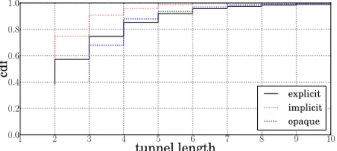
Figure 5: Distribution of LSP length by tunnel type. We find that the distribution of tunnel lengths is similar for explicit and opaque tunnels. There is a higher fraction of short implicit tunnels, which we believe is caused by limitations in our methodology.
signatures, then we infer that more than 11% of IP addresses belong to LSRs, and half of these are identified only through signatures. More than half of explicitly labelled IP addresses (≈ 66%) also exhibit either q-ttl (48%) or u-turn (41%) signatures. The fraction of explicitly labelled IP addresses covered by u-turn signatures is lower because 30% of IP addresses probed did not respond to ping. However, more IP addresses with u-turn signatures did not intersect with explicitly identified LSRs than did IP addresses with q-ttl signatures.
These results can be explained as follows: (1) the IP level view is biased due to false signatures derived from small isolated u-turn delta ∈ [2, 3], and (2) there exists some de-pendence between LSRs that include ICMP extensions and exhibit the q-ttl signature. To overcome the first limitation and accurately quantify the fraction of tunnels that are im-plicit, we decide to focus on tunnels whose lengths are at least 3. For explicit tunnels that are longer than 3 hops, u-turn and q-ttl signatures are found in more than 75% of explicit tunnels; this value is almost constant for all tun-nels between 3 and 10 hops in length. We therefore infer that short u-turn signatures induce an overestimation of the fraction of MPLS tunnels that are implicit. Finally, we find that 36% of tunnels at least three hops in length that were inferred with q-ttl and u-turn signatures (implicit tunnels) do not intersect with explicit tunnels.
6.3
Quantification
Assuming our signatures are able to cover the same frac-tion of implicit tunnels as explicit tunnels, we deduce there are approximatively half as many implicit tunnels as there are explicit tunnels (0.36 ×4
3 ≈0.5). This evaluation may
overestimate the fraction of tunnels that are implicit: if a single hop does not exhibit a signature then we may infer a sequence of short implicit tunnels rather than a single longer implicit tunnel. Therefore, our estimation of the fraction of MPLS tunnels that are implicit is likely to be an upper bound.
Figure 4 plots the relative fractions of unique explicit and implicit tunnels inferred in paths traced by each monitor. We split explicit tunnels into two parts; tunnels where there was q-ttl or u-turn signature overlap, and tunnels where there was none. For most monitors, roughly 60% of explicit signatures are covered by our signatures. However, the num-ber of tunnels inferred as implicit is much more variable, and we do not believe the fraction of implicit MPLS tunnels compared to explicit MPLS tunnels depends this much on
monitor location. We believe routing policies towards our monitors can lead to an overestimation of the number of im-plicit tunnels. Excluding the monitors where a large fraction of tunnels inferred are implicit, which we argue are outliers caused by measurement error, suggests implicit tunnels are three times less prevalent than explicit tunnels.
Figure 5 plots the length of each type of MPLS tunnel inferred. In our data, implicit tunnels are shorter than ex-plicit tunnels, mostly between two and three hops, as shown in figure 5. As MPLS forwarding policies may differ accord-ing to each monitor, usaccord-ing additional monitors allows us to reveal more u-turn signatures. However, it also can produce false distinct implicit tunnels.
Performing the same analysis considering the echo-reply TTL maximizing each u-turn delta, we notice that our sig-natures cover about 80% of explicit tunnels while 41% of them do not intersect any explicit tunnels (reported to their quantity for tunnels longer than two hops). Maximizing u-turn delta, we obtain a similar result ( 1
0.8 ×0.41 ≈ 0.5).
Implicit tunnels seems to be between two and three times less numerous than explicit ones.
7.
OPAQUE TUNNELS
Opaque tunnels refer to tunnels whose Ingress LER does not enable the ttl-propagate option but where the LH en-ables RFC4950. Only the LH is visible and the opaque tun-nel appears as a single-hop LSP, the remainder of the tuntun-nel being hidden from traceroute (see figure 1). We declare each (Ingress-LER, LH) pair to be a unique opaque tunnel.
7.1
Inference Methodology
The LSE-TTL returned by the LH in the time-exceeded reply indicates the presence of an opaque tunnel and its length, i.e., the number of hidden LSRs. When the ttl-pro-pagate option is not activated, the ingress LER initialises the LSE-TTL to 255 so that the packet is unlikely to expire in the tunnel. Each LSR decrements the TTL, so when the LH router receives the packet the LSE-TTL will be 255 − (n + 1) for a tunnel of n hops. Note that an opaque tunnel of one hop is equivalent to an explicit tunnel of one hop and we cannot distinguish them.
In figure 1 the Ingress LER R1 sets the MPLS TTL to
255, rendering the tunnel opaque; at the LH (router R4) the
LSE-TTL will be 253, indicating that the tunnel obscures two LSRs. Based on this basic computation, we can estimate the length of an opaque tunnel even if we are not able to reveal its internal LSRs.
It is possible that the LH LSR may not include RFC4950 extensions if it first pops the last MPLS label from the packet before it constructs the ICMP time-exceeded re-ply. If this happens, the LSP falls into the invisible cate-gory. Using our own MPLS testbed, we notice that Cisco LH LSRs return an MPLS header in their ICMP time-exceeded replies when the ttl-propagate option is disabled at the Ingress LER. Thus, we can reasonably conclude that in most cases, the LH routers of opaque tunnels are visible.
7.2
Quantification
In our measurement experiment, opaque tunnels were not prevalent. We find that opaque tunnels are approximately twenty times less prevalent than explicit tunnels. This is likely to be a lower bound since we only count the LH of opaque tunnels; unique paths between the ingress LER and
the LH are hidden. Regardless, the most significant con-tribution is the methodology to detect opaque tunnels and avoid the inference of false router-level links.
Half of the opaque tunnels that we observed in our data are short, between two and three routers, as shown in fig-ure 5. We encountered two opaque tunnels made of 20 LSRs. It is possible to estimate the number of hidden and false links inferred when using traceroute to discover the IP-level Internet topology. Figure 1 shows how missing two routers can lead to a false inference of a link between R1 and R4.
The distribution of opaque tunnel length gives a hint of the router-level links missed due to opaque tunnels.
It is sometimes possible to infer the LSRs inside an opaque tunnel using additional traceroute measurements. The pro-cess to do so is iterative; it begins with a traceroute towards the LH router. Assuming the use of PHP, a new LH LSR may reveal itself with a time-exceeded message one hop be-fore the LH router we tracerouted. The process continues until the ingress LER is reached. Unfortunately, in practice, most internal hops do not respond to traceroute and cannot be determined.
8.
CONCLUSION
MPLS is commonly deployed in today’s Internet; in our data, at least 30% of traceroutes from most vantage points reveal explicit MPLS tunnels and more than 5% of collected IP interfaces explicitly exhibit MPLS capability. However, explicit tunnels are only one type of MPLS tunnel. In this paper, we developed fingerprinting mechanisms to (1) infer implicit tunnels which hide the use of MPLS but do not obscure the underlying links, and (2) infer opaque tunnels which obscure the underlying links but do not hide the use of MPLS to do so. We estimate that, in addition to the substantial deployment of explicit tunnels, there are half as many of implicit tunnels deployed (upper bound) and twenty times fewer opaque tunnels deployed (lower bound).
In this paper, we did not investigate invisible tunnels. Given the tendencies observed in this paper (i.e., implicit tunnels are less prevalent than explicit tunnels and opaque tunnels are less numerous than implicit tunnels), we be-lieve that invisible tunnels are very infrequent. Assuming the independence of the two MPLS features (RFC4950 and ttl-propagate), we estimate that invisible tunnels are 40 to 50 times less numerous than explicit tunnels. Future work should help us to refine this analysis.
The state of the art in Internet topology measurement is essentially and necessarily a set of hacks, which introduce many sources of possible errors. Opaque and invisible tun-nels can introduce false IP-level links into maps derived from traceroute data and can affect graph characteristics such as router degree. Our methodology to infer opaque tunnels al-lows high-degree nodes caused by these tunnels to be iden-tified and their impact on graph properties to be analysed.
9.
REFERENCES
[1] E. Rosen, A. Viswanathan, and R. Callon, “Multiprotocol label switching architecture,” Internet Engineering Task Force, RFC 3031, January 2001.
[2] K. Muthukrishnan and A. Malis, “A core MPLS IP VPN architecture,” Internet Engineering Task Force, RFC 2917, September 2000.
[3] C. Srinivasan, L. P. Bloomberg, A. Viswanathan, and T. Nadeau, “Multiprotocol label switching (MPLS) traffic engineering (TE) management information base (MIB),” Internet Engineering Task Force, RFC 3812, June 2004. [4] X. Xiao, A. Hannan, and B. Bailey, “Traffic engineering
with MPLS in the Internet,” IEEE Network Magazine, vol. 14, no. 2, April 2000.
[5] L. Andersson, I. Minei, and T. Thomas, “LDP
specification,” Internet Engineering Task Force, RFC 5036, October 2007.
[6] A. Farrel, A. Ayyangar, and J.-P. Vasseur, “Inter-domain MPLS and GMPLS traffic engineering – resource reservation protocol-traffic engineering (RSVP-TE extensions),” Internet Engineering Task Force, RFC 5151, February 2008.
[7] R. Bonica, D. Gan, D. Tappan, and C. Pignataro, “ICMP extensions for multiprotocol label switching,” Internet Engineering Task Force, RFC 4950, August 2007. [8] ——, “Extended ICMP to support multi-part messages,”
Internet Engineering Task Force, RFC 4884, April 2007. [9] “NANOG traceroute,” ftp://ftp.netbsd.org/pub/NetBSD/
packages/distfiles/traceroute-nanog/traceroute.c.
[10] L. De Ghein, MPLS Fundamentals. Cisco Press,
November 2006.
[11] J. Sommers, B. Eriksson, and P. Barford, “On the
prevalence and characteristics of MPLS deployments in the open Internet,” in ACM SIGCOMM Internet Measurement Conference, November 2011.
[12] R. Sherwood, A. Bender, and N. Spring, “Discarte: a disjunctive Internet cartographer,” in ACM SIGCOMM, August 2008.
[13] B. Augustin, X. Cuvellier, B. Orgogozo, F. Viger, T. Friedman, M. Latapy, C. Magnien, and R. Teixeira, “Avoiding traceroute anomalies with Paris traceroute,” in ACM SIGCOMM Internet Measurement Conference, October 2006.
[14] University of Oregon, “Route views, University of Oregon Route Views project,” http://www.routeviews.org/. [15] M. Luckie, “Scamper: a scalable and extensible packet
prober for active measurement of the Internet,” in ACM SIGCOMM Internet Measurement Conference, November 2010.
[16] B. Augustin, R. Teixeira, and T. Friedman, “Measuring load-balanced paths in the Internet,” in ACM SIGCOMM Internet Measurement Conference, October 2007.