HAL Id: hal-00683452
https://hal.archives-ouvertes.fr/hal-00683452
Submitted on 29 Mar 2012
HAL is a multi-disciplinary open access
archive for the deposit and dissemination of
sci-entific research documents, whether they are
pub-lished or not. The documents may come from
teaching and research institutions in France or
abroad, or from public or private research centers.
L’archive ouverte pluridisciplinaire HAL, est
destinée au dépôt et à la diffusion de documents
scientifiques de niveau recherche, publiés ou non,
émanant des établissements d’enseignement et de
recherche français ou étrangers, des laboratoires
publics ou privés.
Blind Source Separation for Robot Audition using Fixed
Beamforming with HRTFs
Mounira Maazaoui, Yves Grenier, Karim Abed-Meraim
To cite this version:
Mounira Maazaoui, Yves Grenier, Karim Abed-Meraim. Blind Source Separation for Robot
Audi-tion using Fixed Beamforming with HRTFs. 12th Annual Conference of the InternaAudi-tional Speech
Communication Association (Interspeech-2011), Sep 2011, Florence, Italy. �hal-00683452�
Blind Source Separation for Robot Audition using Fixed Beamforming with
HRTFs
Mounira Maazaoui, Yves Grenier and Karim Abed-Meraim
Institut TELECOM, TELECOM ParisTech, CNRS-LTCI 37/39, rue Dareau, 75014, Paris, France
[email protected], [email protected], [email protected]
Abstract
We present a two stage blind source separation (BSS) algorithm for robot audition. The algorithm is based on a beamforming preprocessing and a BSS algorithm using a sparsity separation criterion. Before the BSS step, we filter the sensors outputs by beamforming filters to reduce the reverberation and the en-vironmental noise. As we are in a robot audition context, the manifold of the sensor array in this case is hard to model, so we use pre-measured Head Related Transfer Functions (HRTFs) to estimate the beamforming filters. In this article, we show the good performance of this method as compared to a single stage BSS only method.
Index Terms: blind source separation, beamforming, robot au-dition
1. Introduction
Robot audition consists in the aptitude of an humanoid to under-stand its acoustic environment, separate and localize sources, identify speakers and recognize their emotions. This complex task is one of the target points of the ROMEOproject [1]. This project aims to build an humanoid (ROMEO) to help aged peo-ple in their everyday lives. In this project, we focus on blind source separation (BSS) using a microphone array (more than 2 sensors). In a blind source separation task, the separation should be done from the received microphone signals without prior knowledge of the mixing process. The only knowledge is limited to the array geometry. Source separation is the most im-portant step for human-robot interaction: it allows latter tasks like speakers identification, speech and motion recognition and environmental sound analysis.
Blind source separation problem has been tackled several times [2] and one of the main challenges remains to have good BSS performance in a high reverberant environments. One way to handle the reverberation problem is beamforming. Beam-forming consists in estimating a spatial filter that operates on the outputs of a microphone array in order to form a beam with a desired directivity pattern [3]. It is useful for many purposes, particularly in enhancing a desired signal from its measurement corrupted by noise, competing sources and reverberation [3]. Beamforming can be fixed or adaptive. A fixed beamforming, contrarily to the adaptive one, does not depend on the sensors data, the beamformer is built for a set of fixed desired directions. In this article, we propose a two stage blind source separation technique where a fixed beamforming is used as a preprocess-ing. However, in a beamforming task, we need to know the manifold of the sensor array, which is sometimes hard to model
This work is funded by the Ile-de-France region, the General Di-rectorate for Competitiveness, Industry and Services (DGCIS) and the City of Paris, as a part of the ROMEO project.
for the robot audition case. To overcome the problem of the ar-ray geometry modeling and take into account the influence of the robot’s head on the received signals, we propose to use the Head Related Transfer Functions (HRTFs) of the robot’s head to build the fixed beamformer.
Wang et al. propose to use a beamforming preprocessing where the steering directions are the direction of arrivals of the sources [4]. This suppose that the direction of arrival are known a priori. The authors evaluate their method in a deter-mined case (2 and 4 sources) with a circular microphone array. Saruwatari et al. present a combined Independent Component Analysis (ICA) and beamforming method: first they perform a subband ICA and estimate the direction of arrivals (DOA) of the sources using the directivity patterns, second they use the estimated DOA to build a null beamforming, and third they in-tegrate the subband ICA and the null beamforming by select-ing the most suitable separation matrix in each frequency [5]. In this article, we propose to use a fixed beamforming prepro-cessing with fixed steering directions, independently from the direction of arrival of the sources, and we compare this prepro-cessing method to the Wang et al. one. We are interested in studying the effect of the beamforming as a preprocessing tool so we are not going to include the algorithm of [5] in our eval-uation (the authors of [5] use the beamforming as a separation method alternatively with ICA). We present promising results using two different fixed beamformers as preprocessing and a sparsity based BSS algorithm.
2. Signal model
Assume N sound sources s (t) = [s1(t) , . . . , sN(t)]T and
an array of M microphones. The outputs of the sensors array are denoted by x (t) = [x1(t) , . . . , xM(t)]T, where t is the
time index and M ≥ N . In a general case, the output signals in the time domain are modeled as the sum of the convolution between the sound sources and the impulse responses of the different propagation paths between the sources and the sensors, truncated at the length of L + 1:
x (t) =
L
X
l=0
h (l) s (t − l) + n (t) (1) where h (l) is the lthimpulse response matrix coefficient
and n (t) is a noise vector. In the frequency domain, when the analysis window of the Short Time Fourier Transform (STFT) is longer than the length of the mixing filter, the output signals at the time-frequency bin (f, k) can be approximated as:
X (f, k) ' H (f ) S (f, k) (2) where X (respectively S) is the STFT of {x (t)}1≤t≤T (re-spectively {s (t)}1≤t≤T) and H is the Fourier transform of the
mixing filters {h (l)}0≤l≤L. Our goal is to find, for each fre-quency bin, a separation matrix F (f ) that leads to an estimation of the original sources:
Y (f, k) = F (f ) X (f, k) (3) This introduces the well known permutation and scaling problems: from one frequency to the adjacent one, the order and the scale of the estimated sources may be different. The permutation problem can be solved by the method described in [6] based on the signals correlation between two adjacent fre-quencies. The scale problem is solved by the method proposed in [7]. The sources in the time domain can be recovered by taking the inverse short time Fourier transform of the estimated sources in the frequency domain, after solving the permutation problem.
3. Combined beamforming and BSS
algorithm
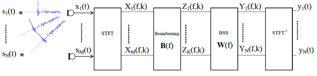
We present here a two step blind separation algorithm based on a fixed beamforming preprocessing (cf. figure 1).
3.1. Beamforming pre-processing We consider {B (f )}
1≤f ≤Nf2 a set of fixed beamforming filters
of size K × M , where Nf is the length of the Fourier analysis
window and K is the number of the desired beams, K ≥ N . Those filters are calculated beforehand (cf. section 4). The out-puts of the beamformers at each frequency f are:
Z (f, k) = B (f ) X (f, k) (4) The role on the beamformer is essentially to reduce the reverberation (and consequently, equation 2 is better satisfied leading to improved BSS quality) and the interferences coming from space directions other than the looked up ones.
3.2. Blind source separation
The blind source separation step consists in estimating a sep-aration matrix W (f ) that leads to separated sources at each frequency bin f . The separation matrix is estimated from the beamformers outputs Z (f, k), the estimated sources are then written as:
Y (f, k) = W (f ) Z (f, k) (5) The separation matrix W (f ) is estimated using a sparsity criterion. We assume that the STFT of the sources are the spars-est state to reach and we use the l1norm minimization criterion:
min W N X i=1 NT X k=1 |Yi(f, k)| such that kWk = 1 (6)
where Yi(f, k) is the (f, k)thbin of the ithsource and k.k
is any matrix norm. The update equation of W (f ) using the natural gradient descent technique [8] is:
Wt+1= Wt− µ∇ψ (Wt) WTtWt (7)
where ψ (W) = PN i=1
PNT
k=1|Yi(f, k)|, ∇ψ (W) is the
gradient of ψ (W) and t refers to the iteration (or time for an adaptive processing) index. The final separation matrix F is:
F (f ) = W (f ) B (f ) (8)
4. Fixed beamforming with HRTFs
In the case of robot audition, the geometry of the microphone array is fixed once for all. Once the array geometry is fixed and the desired steering direction is determined (by a localization technique or arbitrarily), the fixed beamformer takes full ad-vantage of these spatial information to design the desired beam pattern. Thus, the desired characteristics of the beam pattern (the beamwidth, the amplitude of the sidelobes and the position of nulls) are obtained for all scenarii and calculated only once.
To design a fixed beamformer that will achieve the desired beam pattern (according to a desired direction response), the least-square (LS) technique is used [3]. In the case of robot au-dition, the microphone are often fixed in the head of the robot and it is generally hard to know exactly the manifold of the microphone array (cf. figure 5). Besides, the phase and magni-tude response models of the steering vectors do not take into account the influence of the head on the surrounding acous-tic fields. So we propose to use the Head Related Transfer Functions (HRTFs) as steering vectors {a (f, θ)}θ∈Θ, where Θ = {θ1, . . . , θNS} is a group of NSa priorichosen steering
directions (cf. figure 2). The HRTFs characterize how the signal emitted from a specific direction is received at a sensor fixed in a head. It takes into account the geometry and the manifold of the head, and thus of the microphone array. Let hm(f, θ) be
the HRTF at frequency f from the emission point located at θ to the mthsensor. The steering vector is then:
a (f, θ) = [h1(f, θ) , . . . , hM(f, θ)]T (9)
Given equation (9), one can express the normalized LS beam-former for a desired direction θias [3]:
b (f, θi) = R−1aa(f ) a (f, θi) aH(f, θ i) R−1aa(f ) a (f, θi) (10) where R−1aa(f ) = N1 S P θ∈Θa (f, θ) a H (f, θ). Given K desired steering directions θ1, . . . , θK, the beamforming matrix
B (f ) is:
B (f ) = [b (f, θ1) , . . . , b (f, θK)]T (11)
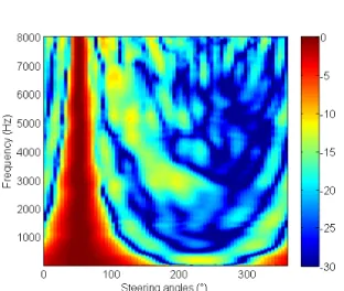
Figure 2: Example of a beam pattern using HRTFs for θi= 50°
Figure 1: The processing scheme of the combined beamforming-BSS algorithm
4.1. Beamforming with known DOA
If the direction-of-arrivals (DOAs) of the sources are known a priori, mainly by a source localization method, the beamform-ing filters are estimated usbeamform-ing this spatial information of the sources location (cf. figure 3). Therefore, the desired directions are the DOAs of the sources and we select the corresponding HRTFs to build the desired response vectors a (f, θ).
Figure 3: Beamforming with known DOAs
4.2. Beamforming with fixed DOA
Estimating the DOAs of the sources is time consuming and not always accurate in the reverberant environments. As an alterna-tive solution, we propose to build K fixed beams with arbitrary desired directions, and then chose the N beamformer outputs with the highest energy, corresponding to the beams that are the closest to the sources (we suppose that the energy of the sources are quite close). The K directions are chosen in such a way they cover all useful space directions (cf. figure 4).
In general, the sources may have a big difference in their energy levels and the source that has the highest energy could be detected more than once by different beams. So the selection of the outputs with the highest energy is done in such a way that they are not correlated, i.e. their coherence is below a certain threshold fixed a priori.
5. Experiments and results
5.1. Experimental database
To evaluate the proposed BSS techniques, we built two databases: a HRTFs database and a speech database. We recorded the HRTF database in the anechoïc room of Telecom ParisTech (cf. figure 5). As we are in a robot audition context, we model the future robot by a child size dummy (1m20) for the sound ac-quisition process, with 16 sensors fixed in its head (cf. figure 5). We measured 504 HRTF for each microphone as follow:
Figure 4: Beamforming with fixed steering directions
Figure 5: The dummy in the anechoïc room (left) and the mi-crophone array of 16 sensors (right)
• 72 azimuth angles from 0° to 355° with a 5° step • 7 elevation angles: -40°, -27°, 0°, 20°, 45°, 60° and 90° The HRTFs were measured by a Golay codes process [9] at a sampling frequency of 48 KHz downsampled to 16 KHz. The HRTF database is available for download1.
We also recorded, with the same dummy, a reverberant speech database to evaluate and compare the proposed methods. The test signals were recorded in a moderately reverberant room which reverberation time is RT30= 300 ms (cf. figure ??). The
output signals x (t) are the convolutions of 10 pairs of speech sources (male and female speaking french and English) by the impulse responses {h (l)}0≤l≤Lmeasured from two angles of arrivals. We used 3 different pairs of DOAs on the horizontal plan (the reference is the head of Theo where the elevation =0°): 0°/-30°, 0°/27° and 0°/90°.
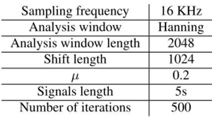
The characteristics of the signals and the BSS algorithms are summarized in table 1.
1http://www.tsi.telecom-paristech.fr/aao/?p=
Sampling frequency 16 KHz Analysis window Hanning Analysis window length 2048
Shift length 1024
µ 0.2
Signals length 5s Number of iterations 500
Table 1: Parameters of the blind source separation algorithms
5.2. Results and discussion
We evaluate the proposed two stage algorithm by the Signal-to-Interference Ratio (SIR) and the Signal-to-Distortion Ratio (SDR) calculated using the BSS-eval toolbox [10]. The follow-ing results are the mean SIR (cf. figure 6) and the mean SDR (cf. figure 7) of 10 pairs of source separation cases from dif-ferent directions of arrivals. The algorithms that we evaluate in this section are:
• Sparsity based BSS algorithm (BSS)
• Two stage algorithm with know DOAs (K-DOA+ BSS) • Two stage algorithm with fixed DOAs: 7 beams from -90
to 90 with a step of 30° (F-DOA[30°]+ BSS)
• Two stage algorithm with fixed DOAs: 13 beams from -90 to 90 with a step of 15° (F-DOA[15°]+ BSS)
Figure 6: SIR comparison with different direction-of-arrivals (DOA)
The results show an improvement of the SIR when the beam-forming preprocessing is used. The SDR is considerably im-proved in the case of known DOAs, as no distortions are intro-duced by a difference between the fixed steering direction and the real DOA. Some errors may occur in the selection of the beams with the highest energy in the case of the fixed DOAs beamforming, especially in the low frequencies and this may affect the SDR and SIR performance. But as the results show, we still have good performance with the fixed DOA beamform-ing preprocessbeamform-ing. We also have a gain in the processbeamform-ing time as we do not have to estimate the DOAs in each separation case.
6. Conclusion
In this article, we present a two stage blind source separation algorithm for robot audition. This algorithm is based on a fixed beamforming preprocessing, with known or fixed DOAs and a
Figure 7: SDR comparison with different direction-of-arrivals (DOA)
BSS algorithm exploiting the sparsity of the sources in the time-frequency domain. The beamforming preprocessing improves the separation performance as it reduces the reverberation and noise effects. The maximum gain is obtained when the sources DOAs are known. However, we propose also a beamforming preprocessing with fixed DOAs that has good performance and do not use an estimation of the DOAs, which represent a gain in the processing time.
7. References
[1] Romeo project: www.projetromeo.com.
[2] P. Comon and C. Jutten, Handbook of Blind Source Separation , Independent Component Analysis and Applications. Elsevier, 2010.
[3] J. Benesty, J. Chen, and Y. Huang, Microphone Array Signal Processing, Chapter 3: Conventional beamforming techniques, 1st ed. Springer, 2008.
[4] H. D. Lin Wang and F. Yin, “Combining superdirective beam-forming and frequency-domain blind source separation for highly reverberant signals,” in EURASIP Journal on Audio, Speech, and Music Processing, vol. 2010, 2010.
[5] H. Saruwatari, S. Kurita, K. Takeda, F. Itakura, T. Nishikawa, and K. Shikano, “Blind source separation combining independent component analysis and beamforming,” EURASIP Journal on Ap-plied Signal Processing, pp. 1135–1146, 2003.
[6] W. Weihua and H. Fenggang, “Improved method for solving per-mutation problem of frequency domain blind source separation,” 6th IEEE International Conference on Industrial Informatics, IN-DIN 2008, Daejeon, pp. 703–706, July 2008.
[7] S. Douglas and M. Gupta, “Scaled natural gradient algorithms for instantaneous and convolutive blind source separation,” in IEEE International Conference on Acoustics, Speech and Signal Pro-cessing. ICASSP 2007, Honolulu, HI, vol. 2, Apr. 2007, pp. II–637 –II–640.
[8] S. Amari, A. Cichocki, and H. H. Yang, A New Learning Algo-rithm for Blind Signal Separation. MIT Press, 1996, pp. 757– 763.
[9] S. Foster, “Impulse response measurement using golay codes,” in IEEE International Conference on Acoustics, Speech, and Signal Processing, ICASSP ’86, vol. 11, Apr. 1986, pp. 929 – 932. [10] E. Vincent, R. Gribonval, and C. Fevotte, “Performance
measure-ment in blind audio source separation,” in IEEE Transactions on Audio, Speech, and Language Processing, vol. 14, July 2006, pp. 1462 –1469.