HAL Id: hal-01004982
https://hal.archives-ouvertes.fr/hal-01004982
Submitted on 12 Feb 2017
HAL is a multi-disciplinary open access
archive for the deposit and dissemination of
sci-entific research documents, whether they are
pub-lished or not. The documents may come from
teaching and research institutions in France or
abroad, or from public or private research centers.
L’archive ouverte pluridisciplinaire HAL, est
destinée au dépôt et à la diffusion de documents
scientifiques de niveau recherche, publiés ou non,
émanant des établissements d’enseignement et de
recherche français ou étrangers, des laboratoires
publics ou privés.
Distributed under a Creative Commons Attribution| 4.0 International License
An anisotropic non linear elastic model for particulate
materials
Pierre Yves Hicher, Ching S. Chang
To cite this version:
Pierre Yves Hicher, Ching S. Chang. An anisotropic non linear elastic model for particulate materials.
Journal of Geotechnical and Geoenvironmental Engineering, American Society of Civil Engineers,
2006, 132 (8), pp.1052-1061. �10.1061/(ASCE)1090-0241(2006)132:8(1052)�. �hal-01004982�
Anisotropic Nonlinear Elastic Model for Particulate Materials
P.-Y. Hicher
1and C. S. Chang
2This paper presents the development of an elastic model for particulate materials based on micromechanics considerations. A particulate material is considered as an assembly of particles. The stress–strain relationship for an assembly can be determined by integrating the behavior of the interparticle contacts in all orientations and using a static hypothesis which relates the average stress of the granular assembly to a mean field of particle contact forces. Hypothesizing a Hertz–Mindlin law for the particle contacts leads to an elastic nonlinear behavior of the particulate material, we were able to determine the elastic constants of the granular assembly based on the properties of the particle contacts. The numerical predictions, compared to the results obtained during experimental studies on different granular materials, show that the model is capable of taking into account both the influence of the inherent anisotropy and the influence of the stress-induced anisotropy for different stress conditions.
Introduction
Particulate materials, such as soils or powders, can be considered as a collection of particles of different sizes and shapes. These discontinuous media can be represented by fictitious continuous media whose mechanical properties should depend on geometric arrangement and contact interactions between interacting par-ticles. It has been experimentally shown that the elastic properties of such materials depend on many parameters, such as the mate-rial type, the stress condition, the void ratio, the coordination number or the packing structure共Hardin and Black 1966; Hardin and Drnevich 1972; Iwasaki and Tatsuoka 1977; Chung et al. 1984; Lade and Nelson 1987; Hicher 1996兲. However, it is not easy to predict elastic moduli for particulate material. The main difficulty lies in the complex behavior of stress dependency lead-ing to nonlinear behavior and stress-induced anisotropy. Further-more, inherent anisotropic behavior occurs due to the mode of deposition. Recent developments in measuring techniques have allowed us to investigate more accurately the behavior of particu-late media at very small strains, giving a more comprehensive insight into their elastic properties along different stress paths.
In previous works on granular mechanics, several empirical equations were proposed in the prediction of elastic moduli
共Hicks and Monismith 1971; Hardin and Drnevich 1972;
Boyce 1980; Brown and Pappin 1981; Biarez and Hicher 1994; Santha 1994兲. These equations were derived from curve fitting to
measured data. Therefore, the equations usually work well only in a limited range of stress conditions.
Another approach to the prediction of elastic moduli is based on micromechanics in which the granular material is considered as an assembly of particles. The moduli can be predicted directly from the properties of the constituent particles, for example, as in the work by Chang et al.共1989兲 and Ng and Petrakis 共1996兲. This approach provides a better understanding of the pressure sensitive behavior of granular media. However, under deviatoric stress con-ditions, the prediction is computationally intensive. It does not provide a straightforward equation as a prediction tool.
In this study, a constitutive model is developed from micro-scale behavior of interacting particles using a static hypothesis
共Cambou et al. 1995; Chang and Gao 1996; Liao et al. 1997兲,
which relates the average stress of the granular assembly to a mean field of particle contact forces. Comparisons with discrete element models for particle assemblies have shown that the static hypothesis leads to representative results. Using a static hypoth-esis, the particle displacements are considered to fluctuate around a mean displacement field that represents the least square fit for the actual displacements共Liao et al. 1997兲. This leads to a more relaxed kinematic condition in comparison to the kinematic hypothesis.
The determination of the elastic constants of a granular assem-bly based on the properties of interparticle contacts will be dis-cussed and the predictions of soil modulus under different loading conditions will be compared to experimental results obtained from different granular materials.
Micromechanical Approach
In recent years, several studies have been devoted to the elastic characteristics of granular materials within the micro-mechanical framework共Walton 1987; Chang 1988; Jenkins 1988; Rothenburg and Bathurst 1989; Chang and Liao 1994; Cambou et al. 1995兲. All these studies assume fundamentally the following two relationships:
1. Interparticle contact law—This provides the relationship be-tween force and displacement at an interparticle contact; and 1Research Institute in Civil and Mechanical Engineering, UMR CNRS
6183, Ecole Centrale Nantes, Univ. of Nantes, Nantes, France.
2Professor, Dept. of Civil and Environmental Engineering, Univ. of
Massachusetts, Amherst, MA 01002 共corresponding author兲. E-mail: chang@ecs.umass.edu
2. Link between micro- and macrovariables. There are two micro–macro relationships:
a. Relationship between interparticle contact forces and the assembly stress; and
b. Relationship between interparticle contact displace-ments and the assembly strain.
Interparticle Behavior
The contact stiffness of an orientation includes normal stiffness,
kn␣, and shear stiffness, kt␣, of the contact plane. The elastic stiff-ness tensor is defined in
fi␣= kij␣␦j␣ 共1兲
where kij␣= interparticle contact stiffness tensor. For two particles
in contact, a local coordinate system can be constructed for each contact with three orthogonal base unit vectors: n is normal to the contact plane; s and t are tangential to the contact plane as shown in Fig. 1.
Let knbe the compressive contact stiffness in normal direction
and ksbe the shear contact stiffness. Assuming the shear contact
stiffness is same in s and t directions and that there is no coupling effect between normal and shear directions, the contact stiffness tensor kqkc can then be expressed in terms of the unit vectors n, s, and t, as
kij␣= kn␣ni␣n␣j+ k␣t共si␣s␣j+ ti␣tj␣兲 共2兲
For each particle contact, the corresponding auxiliary local coordinate system is related to the global coordinate system ac-cording to共see Fig. 1兲
n =共cos ␥, sin ␥ cos , sin ␥ sin 兲
s =共− sin ␥, cos ␥ cos , cos ␥ sin 兲
t =共0, − sin , cos 兲 共3兲
The vector s is on the plane defined by x and n. The vector t is perpendicular to this plane and can be obtained by the cross product of n⫻s. The rolling resistances between two particles are not discussed in this paper.
The value of the stiffness for two elastic spheres can be estimated from Hertz–Mindlin’s formulation 共Mindlin 1969兲. For sand grains, a revised form was adopted共Chang et al. 1989兲 given by kn= kn0
冉
fn Ggl2冊
n ; kt= kt0冉
fn Ggl2冊
n 共4兲where Gg= elastic modulus for the grains; fn= contact force in
normal direction; l = branch length between the two particles; and
kn0, kt0, and n = material constants. For quartz mineral, the Poisson
ratio is about 0.1 and kn0can be approximated by
kn0=
冑
3/2Ggl 共5兲For two spherical particles, the branch length is the particle diam-eter l = d. Using n = 1 / 3, Eqs.共5兲 and 共4兲 are equivalent to Hertz– Mindlin’s contact formulation.
Macro–Micro Relationship
The stress–strain relationship for an assembly can be determined from integrating the behavior of interparticle contacts in all ori-entations. During the integration process, a relationship is re-quired to link the macro- and microvariables. Using the static hypotheses proposed by Liao et al.共1997兲, we obtain the relation between the macrostrain and interparticle displacement共here, we do not consider the finite strain condition兲
u˙j,i= Aik −1
兺
␣=1 N ␦˙j␣l k ␣ 共6兲where ␦˙j= relative displacement between two contact particles and the branch vector lk= vector joining the centers of two contact
particles. It is noted that particle contacts include both direct con-tacts and indirect concon-tacts of neighboring particles associated with a Voronoi polyhedron as discussed by Cambou et al.共2000兲. For convenience, we let N be the total number of contact orien-tations. The variables␦˙j␣and lk␣are defined, respectively, as the averaged values of␦˙jand lkfor all contacts belonging to the␣th
orientation. The fabric tensor in Eq.共6兲 is defined as
Aik=
兺
␣=1
N
li␣lk␣ 共7兲
Using the principle of energy balance and using Eq.共6兲, the mean force on the contact plane of each orientation is
f˙␣j=˙ijAik−1lk␣V 共8兲
In Eq. 共8兲, the stress increment ˙ij can be obtained by the contact forces and branch vectors for contacts in all orientations
共Christofferson et al. 1981; Rothenburg and Selvadurai 1981兲 ˙ij= 1
V␣=1
兺
N
f˙␣jli␣ 共9兲
Applying the defined contact force in Eq. 共8兲, Eq. 共9兲 is un-conditionally satisfied.
Stress–Strain Relationship
The problem is defined as follows. Initially, we know the global variables 共ij and ij兲 for the assembly and the local variables
共fj␣and␦j␣兲 for each contact orientation. For a given loading in-crement, which can be stress control, strain control or mixed mode, out of the 12 global variables 共⌬ij and ⌬ij兲, six of them are unknown. The objective is to determine all global vari-Fig. 1.Local coordinate at interparticle contact
ables 共ij andij兲 and local variables 共f␣j and␦j␣兲 at the end of load increment. For a system with N interparticle orientations, the number of unknowns is 3N for f␣j and 3N for␦␣j. The total number of unknowns is 3N + 3N + 6.
The following constraints must be satisfied:
1. The local constitutive equation, i.e., Eq.共1兲. Since there are three equations for each contact plane orientation, the total number of equations is 3N, N being the total number of in-terparticle orientations.
2. Static hypothesis between global stress and local forces, i.e., Eq.共8兲: the number of equations is 3N.
3. Strain definition between global strain and local displace-ment, i.e., Eq. 共6兲. The number of equations is 6 共strain is symmetric兲.
The total number of unknowns is the same as the total number of equations. Therefore, the solution can be determined.
Using Eqs.共1兲, 共6兲, and 共8兲, the following relationship between stress and strain can be obtained:
u˙i,j= Cijmp˙mp
where Cijmp= Aik −1A mn −1V
兺
␣=1 N 共kjpep兲−1l k ␣l n ␣ 共10兲The summation in Eq.共10兲 can be replaced by an integral over orientations. The integral can lead to a closed-form solution for the elastic modulus of randomly packed equal-size particles
共Chang et al. 1995兲. However, due to the nonlinearity nature of
the local constitutive equation, a numerical calculation with itera-tive process is necessary to carry out the summation in Eq. 共10兲
共Chang and Hicher 2005兲. In order to facilitate the numerical
calculation, the orientations are selected to coincide with the lo-cations of Gauss integration points in a spherical coordinate. Summation over these orientations with the Gauss weighting factor for each orientation is equivalent to determining the inte-gral over orientations. The results were more accurate by using a set of fully symmetric integration points. From a study of the performance of using different numbers of orientations, we found
N艌74 to be adequate 共Chang and Hicher 2005兲.
Particulate Materials with Isotropic Fabric
Isotropic Loading
Extensive studies of the elastic properties of soils have been done in the last 20 years, thanks to the development of new experimen-tal techniques, which measure with a higher degree of accuracy very small deformations of particulate materials. The results have shown that elastic behavior exists only for very small strains, typically smaller than 10−5; the elastic behavior is nonlinear, with
a dependency upon both the actual state of stress and the actual void ratio.
We will at first assume an isotropic fabric for our particulate material. In these conditions, the parameters of the proposed model are as follows:
• Packing density共normalized number of contacts per unit vol-ume兲: =Nl3/ V;
• Mean particle size d; and
• Interparticle elastic constants: Gg,␣, and n.
Note that the total number of contacts N per volume V is normalized by the cube of mean branch length l. The packing
density is unitless. The branch length is defined as the length between centroids of two contact particles. For round particles, the mean branch length is approximately equal to the mean par-ticle size d. The packing density for an assembly of equal-sized spheres can be related to the mean coordination number n¯ and the
void ratio e of the assembly共Chang et al. 1989兲
=Nl3
V =
3n¯
共1 + e兲 共11兲
A relationship between and e obtained for a regular packing of spheres is plotted in Fig. 2.
For a representative volume consisting of a large number of round particles, in which the contact orientations are isotropically distributed, an analytical form of the shear modulus G and the Poisson’s ratio of the granular assembly can be obtained 共Liao et al. 2000兲
G = 5kn␣
6d共3 + 2␣兲 共12兲
= 1 −␣
2 + 3␣ 共13兲
where␣=kt0/ kn0and=packing density. Poisson’s ratio depends
therefore only on the interparticle stiffness ratio␣. Using Eqs. 共4兲 and共5兲, under an isotropic stress c, the shear modulus G can be expressed as
G = Hg1−n
冉
c p0冊
n
共14兲
where p0= reference pressure共p0= 1 MPa in the computations in
this paper兲 and Hg= function depending on the elastic properties of the grains Hg= 5␣ 2
冑
6共3 + 2␣兲Gg冉
3p0 Gg冊
n 共15兲where Ggis defined in Eq.共4兲.
Eq. 共14兲 was derived from spherical grains. In a subsequent discussion, the relationship is extended to sands by empirically determining the packing density from experimental results. The influences of void ratio and confining stress on Young modulus have been experimentally studied for different granular materials
共Hicher 2001兲. The main results are summarized in Fig. 3共a兲. We
can draw the following two conclusions: 共1兲 for a given grain shape there is no influence of the grain size on elastic modulus. This implies that the modulus is dependent on the packing density Fig. 2.Relationship between void ratio and coordination number
共normalized by particle size兲, not on the particle size. 共2兲 The
modulus is dependent on both void ratio and grain size distribu-tion; for a given void ratio, the Young modulus is higher for soils with uniform gradation 共i.e., smaller coefficient of uniformity
Uc= d60/ d10兲. Thus the packing density is no longer a unique
re-lationship with the void ratio e as it was shown in Fig. 2 for an assembly of equal-sized spheres. The grain size distribution should also be a factor influencing the packing density.
Fig. 3共b兲 shows results obtained on different quartzic sands, including some studied in this paper. One can see that the general trend is very similar to Fig. 3共a兲 and confirms the conclusions stated above. If we assume that the grain properties are roughly the same for all these quartzic sands, we can back-calculate, from the experimental results in Fig. 3, the packing densities and establish an empirical relationship between the packing density
and the void ratio e for various coefficients of uniformity Uc 共Fig. 4兲. Mean particle size, d, is not an explicit parameter.
Thus, the parameters of the proposed model are as follows: • Packing density 共obtained from void ratio e and coefficients
of uniformity Uc兲; and
• Particle shear modulus Gg, stiffness ratio␣, and exponent n.
One can therefore determine theoretically the shear modulus of an assembly of particles, knowing the elastic properties of the particles, the grain size distribution Uc, and the void ratio e.
The approach that we adopted in the subsequent study was to determine the parameters of the model through the following procedure. From the test results, we can determine the ratio
␣=kt0/ kn0 directly from the Poisson’s ratio of the assembly 关Eq. 共12兲兴. The packing density can be determined from Fig. 4.
The value of Ggand the coefficient of nonlinearity n can therefore
be determined by fitting predicted and experimental values ob-tained for the material modulus共E or G兲.
Fig. 5 shows the comparison of experimental and numerical results of the Young modulus as a function of void ratio and isotropic stress for glass ballotini 共d50= 1 mm兲 and Hostun sand
共Uc= 1.8, d50= 0.29 mm兲. The measured values of Poisson’s ratio
=0.21 for both glass ballotini and Hostun sand 共Hicher 1998兲,
giving a value of ␣=0.36. The value of Gg= 2,000,000 N / mm2
and n = 0.5 was used for both glass ballotini and Hostun sand. By using the chart in Fig. 4 for packing density , the computed elastic modulus has a very good agreement with experimental results. Similar agreement was also found for the predicted and measured elastic moduli for Toyoura sand, Reid Bedford sand, Ottawa sand, and Ticino sand共the experimental results shown in Fig. 3兲. Results on Toyoura sand and Ticino sand will be dis-cussed in the following sections. This demonstrated that elastic moduli can be predicted accurately for granular materials under an isotropic loading, provided that one can assume the initial isotropy of the packing. This hypothesis will be discussed.
Anisotropic Loading
When the applied state of stress is no longer isotropic, the model will predict a stress-induced anisotropy due to the dependency Fig. 5. Comparison between measured and predicted values of Young’s modulus for glass ballotoni and Hostun sand
Fig. 6.Stress induced anisotropy
Fig. 3.Influence of grain size and distribution on Young modulus
共E and p are in megapascal兲
Fig. 4.Empirical relationship for packing density as function of void ratio and of grain size distribution
of the interparticle contact stiffness with the contact forces. The flexibility matrix can be expressed in the axes of anisotropy as follows:
冦
11 22 33 ␥12 ␥23 ␥31冧
=冤
1 E11 −21 E22 −31 E33 0 0 0 −12 E11 1 E22 −32 E33 0 0 0 −13 E11 −23 E22 1 E33 0 0 0 0 0 0 1 G12 0 0 0 0 0 0 1 G23 0 0 0 0 0 0 1 G31冥
冦
11 22 33 12 23 31冧
共16兲We will consider here only the case of a simple loading path: starting from an isotropic state of stress0, the stress in direction
1 is increased, while the stresses in directions 2 and 3 remain constant. After numerical integration of all interparticle stiffness, the elastic constitutive matrix is found to be cross anisotropic.
The evolution of the elastic constants is plotted in Fig. 6 as a function of the stress ratio1/2. All the components of the
elas-tic matrix increase with the stress ratio, albeit at different rates. The material anisotropy, represented for example by the ratio
E1/ E2, increases with the stress anisotropy.
Particulate Materials with Anisotropic Fabric
One of the main advantages of the model is its capability of taking into account the structural anisotropy. In fact, the decom-position of the constitutive equations along a set of planes allows us to formulate the dependency of the parameters with respect to the orientation. We can thus obtain a response, which depends on the loading orientation in relation to the direction of material anisotropy. In the case of an orthotropic material, the anisotropy can be characterized by a fabric tensor, defined by
关Fij兴 = Fave
冤
1 + a0 0 0 0 1 −a0 2 + 3a22 0 0 0 1 −a0 2 − 3a22冥
共17兲where Fave=共F11+ F22+ F33兲/3. a0 and a22= fabric constants
de-scribing the packing anisotropy共Chang et al. 1995兲. By represent-ing the distribution of contact orientations with a continuous spherical harmonic expansion in three dimensions, it was found
关see Chang and Misra 共1990兲兴 that the fabric tensor matches the
distribution described by a truncated form of the expansion con-sisting of second-order terms, given by
E ¯ 共␥,兲 =Fave 4
冋
1 + a0 4共3 cos 2␥ + 1兲 + 3a22sin 2␥ cos 2册
共18兲The meaning of angles and ␥ is given in Fig. 1.
For a cross-anisotropic material, a22becomes equal to zero and
Eq.共18兲 is reduced to E ¯ 共␥,兲 =Fave 4
冋
1 + a0 4共3 cos 2␥ + 1兲册
共19兲In three dimensions, the inherent anisotropy can be repre-sented by a distribution whose major axis often coincides with the vertical direction. An example of distributions with different val-ues of a0is shown in Fig. 7. The anisotropy of the packing struc-ture is responsible to the anisotropy of the mechanical behavior.
When deposited in the gravitational field, granular materials comprise an anisotropic packing structure共or anisotropic fabric兲, often termed inherent anisotropy. Recent experimental studies
共Belloti et al. 1996; Jiang et al. 1997; Hoque and Tatsuoka 1998兲
have demonstrated the influence of inherent anisotropy on the mechanical response of granular materials. The elastic matrix due to this inherent anisotropy can be considered as cross anisotropy. Assuming the vertical and horizontal axes are two principal ma-terial axes, Eq.共16兲 becomes
冦
⌬xx ⌬yy ⌬zz ⌬␥yz ⌬␥zx ⌬␥xy冧
=冤
1 Eh −hh Eh −vh Ev 0 0 0 −hh Eh 1 Eh −vh Ev 0 0 0 −hv Eh −hv Eh 1 Ev 0 0 0 0 0 0 1 Gvh 0 0 0 0 0 0 1 Gvh 0 0 0 0 0 0 2共1 + hh兲 Eh冥
⫻冦
⌬xx ⌬yy ⌬zz ⌬yz ⌬zx ⌬xy冧
共20兲 Isotropic LoadingIn order to demonstrate the capability of the model to take into account an inherent anisotropy, three examples were selected Fig. 7.Distribution of contact orientations with different values of a0
from experimental results obtained by Hoque and Tatsuoka
共1998兲 and Jiang et al. 共1997兲 on different granular materials.
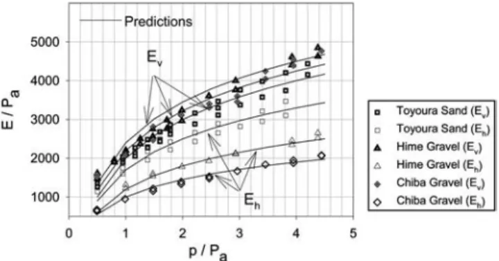
Fig. 8 presents experimental and simulation results on Toyoura sand 共Uc= 1.46, d50= 0.16 mm兲, Hime gravel 共Uc= 1.33,
d50= 1.73 mm兲, and Chiba gravel 共Uc= 10, d50= 8 mm兲. The
specimens were prepared by air pluviation and tested under air-dried conditions. Strains were measured by means of LVDTs placed on the specimen inside the triaxial cell. Measurements of
Evandvhwere obtained by applying a small vertical stress
in-crement⌬vwhile keeping the horizontal stresshconstant
Ev= ⌬v ⌬v and vh= − ⌬h ⌬v 共21兲
When applying a small horizontal stress increment ⌬h
关i.e., ⌬xxin Eq.共20兲兴 while keeping vconstant关i.e., ⌬zz= 0 in
Eq.共20兲兴, Eq. 共20兲 leads to the following relations:
Eh=共1 − hh兲 ⌬h ⌬h and 2hv 1 −hh= − ⌬v ⌬h 共22兲
One can observe from Eq.共22兲 that the two equations are not sufficient to determine the three unknowns: Eh,hv, andhh. The
assumption made by Hoque and Tatsuoka 共1998兲 was hh=vh
under isotropic stress states. Furthermore, due to the limited ac-curacy of lateral strain measurements, Hoque and Tatsuoka be-lieve that the measured values ofhvwere not reliable, and thus
were not reported. This shows the difficulties of measuring with sufficient accuracy all the elastic constants for an anisotropic specimen.
In this study, the same assumption is made concerning
hh. Although it leads to some uncertainty concerning the exact value of Eh, it will not affect the discussion of model
capabi-lities in reproducing the overall behavior of anisotropic granular materials.
Toyoura sand and Hime gravel are both uniformly graded ma-terials with Uc⬍2. The values of vertical moduli Ev共Fig. 8兲 are
in very good accord with the results presented in Fig. 3. The values of horizontal moduli Ehare invariably smaller for Toyoura
sand, Hime gravel, and Chiba gravel. One can use the chart in
Fig. 4 to determine the packing density corresponding to the void ratio of the tested specimens 共e=0.65兲. If we do so, a packing density=2.5 is obtained for Toyoura sand.
A Poisson’s ratio vh= 0.17 was measured during isotropic
loading and the same value was assumed forhh. Estimated from Eq. 共12兲, the corresponding value of ␣=0.45. The ratio between horizontal and vertical moduli Eh/ Evwas found constant during
isotropic loading and equal to 0.9, indicating the packing aniso-tropy. The anisotropy comes from many sources: the particle shape, the packing arrangement, the curvature of interparticle contact, etc. We have no information on these factors. In order for the model to capture this inherent anisotropy, an orientational dependent was assumed, which has the same material axis as the fabric. For a cross-anisotropic material, Eq.共19兲 can be used to define the orientational dependent共␥,兲, in which Fave= and
a0= a. The anisotropy of the packing density a= 0.24 was
deter-mined in order to match the ratio Eh/ Ev. Table 1 summarizes the
parameters for Toyoura sand.
According to void ratios for Hime gravel and Chiba gravel
共Uc⬍2兲, the values of are 4 and 4.2, respectively. The measured
ratio between the horizontal and vertical moduli were
Eh/ Ev= 0.6 for Hime gravel and 0.45 for Chiba gravel. To match
the Eh/ Ev ratios, the anisotropy for the packing density was
a= 1.03 for Hime gravel and 1.5 for Chiba gravel. The anisotropy for␣ is also introduced in order to obtain anisotropic Poisson’s ratio values in accordance with the measured ones 共for Hime gravel,hh=vh= 0.15, and for Chiba gravelhh=vh= 0.25兲. For a
cross-anisotropic material, Eq.共19兲 can be used to define the ori-entational dependent␣共␥,兲, in which Fave=␣ and a0= a␣. Table
2 summarizes the model parameters for these two materials. Comparisons between numerical and experimental results show that the model can represent accurately the influence of inherent anisotropy under isotropic loading. The results also dem-onstrate that the inherent anisotropy does not change during iso-tropic loading. In particular, the ratio between horizontal and ver-tical moduli remains constant. We will, in a second stage, study the evolution of the elastic constants during anisotropic loading.
Anisotropic Loading
The three previous materials were also subjected to different an-isotropic loading. For Toyoura sand and Hime gravel, test pro-grams corresponding to different stress paths lead to various values of the ratioh/v共Hoque and Tatsuoka 1998兲. The
experi-mental results showing the evolution of the elastic properties with the state of stress are given in Fig. 9 along with the results of the numerical simulations. The parameters determined from isotropic loading were used for these calculations 共Tables 1 and 2兲. The experimental results suggest that the Young moduli Evand Ehare
Fig. 8.Isotropic loading on anisotropic Toyoura sand, Hime gravel, and Chiba gravel
Table 1.Elastic Parameters for Toyoura Sand共e=0.65兲
a Gg ␣ n
2.5 0.24 2,100,000 0.45 0.5
Table 2.Model Parameters for Hime Gravel and Chiba Gravel
Material a Gg ␣ a␣ n Hime gravel 共e=0.5兲 0.53 1.03 2,100,000 0.56 0.05 0.5 Chiba gravel 共e=0.49兲 0.36 1.5 2,100,000 0.33 −0.07 0.52
mainly dependent on the vertical and horizontal stressvandh
respectively. Other experimental works 关see for example Belloti et al. 共1996兲 and Kuwano and Jardine 共2002兲兴 reached the same conclusions. However, one can see in Fig. 9 that the evolution of
Evand Ehwithvandhare also influenced by the value of the
stress in the perpendicular direction共i.e., hfor Evandvfor Eh兲.
Numerical simulations show the same pattern and demonstrate the capability of the model to reproduce the observed behavior along anisotropic stress paths. One can notice, however, that the model gives a more pronounced influence of the transverse stress on vertical and horizontal Young moduli. This influence is due to the mode of integration along a set of planes of different ori-entations. Each plane contributes to the assembly behavior and, therefore, the stresses in all directions affect this behavior. Similar results were obtained on Chiba gravel along different stress paths. As a consequence, the stress induced anisotropy, which can be expressed by the influence of the v/h ratio on the Ev/ Eh
ratio, is less marked in the model compared to experimental evi-dence 关Fig. 10共a兲兴. The evolution of Poisson’s ratio vh also
shows an influence of the stress state which is captured by the model, although with less rate of change than the measured one
关Fig. 10共b兲兴.
An extensive study of the elastic behavior of Ticino sand was performed by Bellotti et al.共1996兲. The tests were performed in a large calibration chamber and elastic properties were measured by means of propagating seismic body waves inside the speci-mens. With this technique, it is possible to measure wave pro-pagation velocities in more than two directions 共vertical and horizontal兲, which opens the way to determine all the elastic
constants. In comparison with the previous measurement tech-nique, the advantage is that all the elastic constants can be di-rectly measured. The specimens were prepared by air pluviation, leading to an initial fabric which can be considered, as for the examples examined before, as cross anisotropic in vertical and horizontal axes. Several constant stress ratio tests were performed over a range of values of stress ratio K =h/v from 0.5 to 2.
Results under isotropic loading conditions confirmed that the inherent anisotropy can be considered as cross anisotropic with isotropy in the horizontal plane since the wave velocities pro-pagating in this plane were independent of the direction of propa-gation. The wave velocities either propagated along the z axis or polarized in the vertical plane were always lower than those con-fined in the horizontal plane. These last results lead to lower vertical than horizontal stiffness, contradicting the results dis-cussed previously. Explanation for this phenomenon must await further study.
Considering the physical characteristics of Ticino sand:
Uc= 1.6 and d50= 0.55 mm, values of Evobtained along isotropic
stress paths are in agreement with the results presented in Fig. 3. We can therefore apply the chart in Fig. 4 to determine =1.2 for a given mean unit weight 1.505 MN/ mm3 共relative density
Dr= 41%, e = 0.79兲. Values of Eh/ Ev= 1.21 and n = 0.45 could be
determined from the test results. Measured values ofhhandhh were used to determine the values of␣ in vertical and horizontal directions. Table 3 summarizes the set of model parameters.
Comparison between experimental results and numerical simulations is presented in Fig. 11共a兲. An overall agreement was obtained for the different elastic constants. Constant values of Poisson’s ratios are predicted by the model along the isotropic loading path, contrary to the experimental results which showed a slight increase of hh and a slight decrease of vh andhv. This
Fig. 9. Stress dependency on the horizontal and vertical Young’s modulus for Toyoura sand and Hime gravel
Fig. 10.Stress induced anisotropy in Toyoura sand and Hime gravel
Table 3.Model Parameters for Ticino Sand along Isotropic Loading Path
a Gg ␣ n
0.37 −0.4 2,100,000 0.38 0.45
Fig. 11. Comparison between measured and predicted elastic constants for Ticino sand
could be the result of a certain evolution of the fabric during isotropic loading due to strain induced anisotropy, even if the authors estimated that strain induced anisotropy could be ne-glected in this study. This issue cannot be answered by the model in its present form.
When examining experimental data obtained for different stress ratios, one cannot observe any clear trend in the evolution of elastic constants共see for example in Fig. 11, the evolution of Poisson’s ratios for different stress ratios兲, which could also be due to a change of fabric anisotropy. Therefore, the model param-eters governing the initial anisotropy were assigned for each load-ing condition, given in Table 4. The evolution of the packload-ing density anisotropy ais an indicator of the evolution of the level of anisotropy with the stress ratio.
The results are presented in Fig. 11. Satisfactory agreement is found between experimental results and numerical simulations for moduli. However discrepancies are found in the comparisons for Poisson’s ratio. One should be aware that Poisson’s ratios for an anisotropic material cannot be experimentally determined with accuracy as discussed previously. Therefore, comparisons of mea-sured Poisson’s ratio with numerical simulations are difficult to assess. In any case, the comparisons show that the model captures the general trend for the evolution of elastic constants along stress paths with constant principal stress ratios.
Rotation of Principal Stress Directions
In all examples treated above, the principal stress directions were maintained constant and coincided with the axes of inherent an-isotropy. We will now study the evolution of elastic constants along rotational stress paths. A recent study by Geoffroy et al.
共2003兲 sheds new light on this evolution by means of a new
apparatus, a torsional hollow cylinder device. Measurements of local strains by LVDT permit us to determine the following strain tensor expressed in the axes of initial anisotropy 共vertical z and horizontal r,兲: 关兴 =
冤
rr 0 0 0 ␥z 2 0 ␥z 2 zz冥
=冤
r 0 0 0 ␥ 2 0 ␥ 2 z冥
共23兲Controlling axial, horizontal, and torsion shear stresses al-lowed different loading conditions to be applied with and without stress rotation 关兴 =
冤
rr 0 0 0 z 0 z zz冥
=冤
r 0 0 0 0 z冥
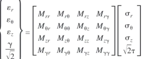
共24兲Therefore, 16 terms of the flexibility matrix can be determined as follows:
冦
r z ␥冑
2冧
=冤
Mrr Mr Mrz Mr␥ Mr M Mz M␥ Mzr Mz Mzz Mz␥ M␥r M␥ M␥z M␥␥冥
冤
r z冑
2冥
共25兲Measurements of wave propagation velocities by bender and extender elements were used for this purpose in addition to LVDT measurements. The tests were performed on Hostun sand pre-pared by air pluviation. Two types of stress paths were applied on the specimens: a triaxial compression loading 共Type C兲 and a torsion after axial loading corresponding to a ratio h/v= 0.5
共Type K兲. The authors did not give any data concerning the
in-herent anisotropy due to the mode of deposition and assumed that the specimens were close to initial isotropy. We will make the same assumption for the purpose of this study, even if the results presented in the previous section have demonstrated that the ma-terial is mainly cross anisotropic in the case of air pluviation preparation. In this condition, the parameters for Hostun sand were adopted.
In their paper, Geoffroy et al. present experimental values only for the two last columns 共eight elastic constants兲 of the elastic matrix in Eq. 共25兲. Comparisons between experimental results and simulations are presented in Fig. 12, where the elastic con-stants are normalized to the value under initial loading condition. For the triaxial loading case, the elastic constants are plotted against normalized stressz/z0. For the torsional tests, the elas-tic constants are plotted against stress ratio /pmean. During
tri-axial loading 共Case C兲 the terms in the last column Mr␥, M␥,
M␥z, and Mz␥should be null and stay null all along the loading. Despite some discrepancy in the measurements, the experimental data remain close to a mean value equal to zero in accordance with the model prediction共Fig. 12兲. During a torsion shear test, these four terms will evolve with the change in the principal stress directions. In the model, these two relations are always verified:
Mr␥= M, M␥z= Mz␥. Comparisons with experimental data show
that the model is capable of capturing reasonably well the evolu-tion of these four parameters during torsion, considering the dis-persion of experimental data.
The evolutions of the terms Mrz and Mzduring triaxial and
torsion tests are also presented in Fig. 12. These two terms are always equal in the model prediction and one can see that, despite the dispersion of the experimental data, the model can predict correctly their evolution during triaxial tests, while their values remain practically constant during torsion shear tests.
Fig. 12 shows the evolution of the terms Mzzand M␥␥. It can
be seen that the model can capture the decrease of these two terms during triaxial loading, which corresponds to an increase in Young and shear moduli with stress ratio. During shearing, these two terms slightly increase with the shear amplitude, correspond-ing to a decrease in Young and shear moduli. Here this tendency can also be predicted by the model.
In conclusion, the model is able to take into account with reasonable accuracy the evolution of the elastic matrix due to stress induced anisotropy, which may be caused by either stress amplitude or rotation of principal stress axes.
Summary and Conclusion
An elastic model for particulate materials was developed based on micromechanics considerations. A particulate material is
consid-Table 4.Sets of Parameters for Ticino Sand for Different Stress Ratios
K a ␣ a␣ n
0.5 0.32 0.11 0.5 0.48 0.45
1.5 0.34 −0.65 0.48 0.67 0.45
ered as an assembly of particles. The stress–strain relationship for the assembly can be determined from integrating the behavior of interparticle contacts in all orientations using a static hypothesis which relates the average stress of the granular assembly to a mean field of particle contact forces. This stress–strain relation-ship leads to an elastic nonlinear behavior of the particulate material.
The elastic coefficients at the level of the assembly depend on the parameters used to define the contact law at the level of the particles. These parameters comprise the contact law itself, i.e., the normal stiffness, kn0, and the shear stiffness as a function of
the normal stiffness, kr0=␣kn0, as well as the packing density
共normalized number of contact per unit volume兲 along a given
plane orientation. The dependency of the normal stiffness on the normal force gives a pressure-dependent behavior for the assem-bly, while the interparticle stiffness ratio␣ determines the value of Poisson’s ratio. The influence of the void ratio of the assembly on the elastic properties is taken into account through the packing density. An empirical relationship was proposed in order to link values of to the void ratio. This relationship was based on results obtained for different granular materials with different grain size distributions.
Inherent anisotropy due to the mode of deposition can be as-sessed by taking into account a dependency of the parameters defining the normalized number of contacts in a given plane on the orientation of this plane. The nonlinear character of the con-tact stiffness leads to a stress-induced anisotropy with regard to the overall behavior of the grain assembly. This stress induced anisotropy includes the effects of the principal stress amplitudes as well as the rotation of the principal stress directions.
The predictions of the model for different stress conditions were compared to the results obtained during several experimen-tal studies on different granular materials. The comparisons showed that the model is capable of taking into account very precisely the influence of the inherent anisotropy. The stress in-duced anisotropy along the different stress paths is also taken into account, but the model allows the transverse stresses to have a
more pronounced influence on Young and shear moduli. This is the result of the way the local equations are integrated. However, it must be pointed out that this discrepancy becomes noticeable for elevated stress ratios. In this regard, several studies have dem-onstrated that the change in the fabric due to strain-induced an-isotropy could no longer be neglected共Kuwano and Jardine 2002; Dano and Hicher 2003兲. Under these conditions, a mechanism of strain-induced anisotropy needs to be introduced in the model, which was not the subject of this study. This could be achieved in future studies, given that an elastoplastic model based on the same numerical concepts as the ones exposed here has recently been developed 共Chang and Hicher 2005兲, which allows nonre-versible strains to be computed that could be used to take into account the fabric evolution and the related evolution of the elas-tic properties.
References
Bellotti, R., Jamiolkowski, M., Lo Presti, D. C. F., and O’Neil, D. A.
共1996兲. “Anisotropy of small strain stiffness in Ticino sand.”
Geotech-nique, 46共1兲, 115–131.
Biarez, J., and Hicher, P.-Y.共1994兲. Elementary mechanics of soil behav-ior, Balkema, Rotterdam, The Netherlands.
Boyce, H. R. 共1980兲. “A nonlinear model for the elastic behaviour of granular materials under repeated loading.” Proc., Int. Symp. Soils under Cyclic and Transient Loading, Vol. 1, Swansea, U.K., 285–294. Brown, S. F., and Pappin, J. W. 共1981兲. “Analysis of pavement with granular bases, layered pavement system.” Transportation Research Record 810, Transportation Research Board, Washington, D.C., 17–23.
Cambou, B., Dedecker, F., and Chaze, M.共2000兲. “Relevant local vari-ables for the change of scale in granular materials.” Constitutive mod-eling of granular materials, Dimitrios Kolymbas, ed., Springer, Ber-lin, 275–290.
Cambou, B., Dubujet, P., Emeriault, F., and Sidoroff, F. 共1995兲. “Homogenization for granular materials.” Eur. J. Mech. A/Solids,
14共2兲, 255–276.
Chang, C. S. 共1988兲. “Micromechanical modeling of constructive rela-tions for granular material.” Micromechanics of granular materials, M. Satake and J. T. Jenkins, eds., Elsevier, Amsterdam, The Nether-lands, 271–279.
Chang, C. S., Chao, S. J., and Chang, Y.共1995兲. “Estimates of elastic moduli for granular materials with anisotropic random packing struc-ture.” Int. J. Solids Struct., 32共14兲, 1989–2008.
Chang, C. S., and Gao, J.共1996兲. “Kinematic and static hypotheses for constitutive modeling of granulates considering particle rotation.” Acta Mech., 115共1–4兲, 213–229.
Chang, C. S., and Hicher, P.-Y. 共2005兲. “An elastoplastic model for granular materials with microstructural considerations.” Int. J. Solids Struct., 42, 4258–4277.
Chang, C. S., and Liao, C. L.共1994兲. “Estimates of elastic modulus for media of randomly packed granules. II.” Appl. Mech. Rev., 47共1兲, 197–206.
Chang, C. S., and Misra, A. L.共1990兲. “Application of uniform strain theory to heterogeneous granular solid.” J. Eng. Mech., 116共10兲, 2310–2328.
Chang, C. S., Sundaram, S. S., and Misra, A.共1989兲. “Initial moduli of particulated mass with frictional contacts.” Int. J. Numer. Analyt. Meth. Geomech., 13共6兲, 629–644.
Christofferson, J. S., Mehrabadi, M. M., and Nemat-Nassar, S.共1981兲. “A micromechanical description on granular material behavior.” ASME J. Appl. Mech., 48, 339–344.
Chung, R. M., Yokel, F. Y., and Drnevich, V. P.共1984兲. “Evaluation of dynamic properties of sands by resonant column testing.” Geotech. Test. J., 7共2兲, 60–69.
Dano, C., and Hicher, P.-Y.共2003兲. “Behavior of uncemented soils and grouted soils before maximum shear strength.” Soils Found., 43共4兲, 13–20.
Geoffroy, H., Di Benedetto, H., Duttine, A., and Sauzeat, C. 共2003兲. “Dynamic and cyclic loading on sands: Results and modelling for general stress-strain conditions.” Proc., 3rd Int. Symp. on Deformation Characteristics of Geomaterials, ISLyon’03, Lyon, France.
Hardin, B. O., and Black, W. L.共1966兲. “Sand stiffness under various triaxial stresses.” J. Soil Mech. Found. Div., 92共1兲, 27–42.
Hardin, B. O., and Drnevich, V. P.共1972兲. “Shear modulus and damping in soils: Measurements and parameter effects.” J. Soil Mech. Found. Div., 98共6兲, 603–624.
Hicher, P.-Y. 共1996兲. “Elastic properties of soils.” J. Geotech. Eng., 122共8兲, 641–648.
Hicher, P.-Y. 共1998兲. “Experimental behaviour of granular materials.” Behaviour of granular materials, B. Cambou, ed., Springer, New York, 1–97.
Hicher, P.-Y. 共2001兲. “Microstructure influence on soil behavior at small strains.” Prefailure deformation characteristics of geomaterials,
M. Jamiolkowski, R. Lancellotta, and P. Lo Presti, eds., Swets & Zellinger, Lisse, The Netherlands, 1291–1297.
Hicks, R. G., and Monismith, C. L.共1971兲. “Factors influencing the re-silient response of granular materials.” Transportation Research Record. 345, Transportation Research Board, National Research Council, Washington, D.C., 15–31.
Hoque, E., and Tatsuoka, F.共1998兲. “Anisotropy in elastic deformation of granular materials.” Soils Found., 38共1兲, 163–179.
Iwasaki, T., and Tatsuoka, F.共1977兲. “Effects of grain size and grading on dynamic shear moduli of sands.” Soils Found., 17共3兲, 19–35. Jenkins, J. T.共1988兲. “Volume change in small strain axisymmetric
de-formations of a granular material.” Micromechanics of granular ma-terials, M. Satake and J. T. Jenkins, eds., Elsevier, Amsterdam, 143– 152.
Jiang, G-L., Tatsuoka, F., Fora, A., and Koseki, J.共1997兲. “Inherent and stress-state-induced anisotropy in very small strain stiffness of a sandy gravel.” Geotechnique, 47共3兲, 509–521.
Kuwano, R., and Jardine, R. 共2002兲. “On the applicability of cross-anisotropic elasticity to granular materials at very small strains.” Geo-technique, 52共10兲, 727–749.
Lade, P. V., and Nelson, R. B.共1987兲. “Modelling the elastic behavior of granular materials.” Int. J. Numer. Analyt. Meth. Geomech., 11共5兲, 521–542.
Liao, C. L., Chan, T. C., Suiker, A. S. J., and Chang, C. S. 共2000兲. “Pressure-dependent elastic moduli of granular assemblies.” Int. J. Numer. Analyt. Meth. Geomech., 24, 265–279.
Liao, C. L., Chang, T. P., Young, D. H., and Chang, C. S.共1997兲. “Stress– strain relationships for granular materials based on the hypothesis of best fit.” Int. J. Solids Struct., 34, 4087–4100.
Mindlin, R. D.共1969兲. “Microstructure in linear elasticity.” Arch. Ration. Mech. Anal., 16, 51–78.
Ng, T. T., and Petrakis, E. 共1996兲. “Small-strain response of random arrays of spheres using discrete elements method.” J. Eng. Mech.,
122共3兲, 239–244.
Rothenburg, L., and Bathurst, R. J.共1989兲. “Analytical study of induced anisotropy in idealized granular materials.” Geotechnique, 39共4兲, 601–614.
Rothenburg, L., and Selvadurai, A. P. S.共1918兲. “Micromechanical defi-nitions of the Cauchy stress tensor for particular media.” Mechanics of structured media, A. P. S. Selvadurai, ed., Elsevier, Amsterdam, 469–486.
Santha, B. L.共1994兲. “Resilient modulus of subgrade soils: Comparison of two constitutive equations.” Transportation Research Record. 1462, Transportation Research Board, Washington, D.C., 213–226. Wallton, K.共1987兲. “The effective elastic moduli of a random packing of