To link to this article :
URL : http://www.ijvr.org/web/search/singleArticle/322
To cite this version : Dubois, Emmanuel and Hamelin, Adrien Worm
Selector: Volume Selection in a 3D Point Cloud Through Adaptive Modelling. (2017) The International Journal of Virtual Reality, vol. 17
(n° 1). pp. 1-20. ISSN 1081-1451
O
pen
A
rchive
T
OULOUSE
A
rchive
O
uverte (
OATAO
)
OATAO is an open access repository that collects the work of Toulouse researchers and makes it freely available over the web where possible.
This is an author-deposited version published in : http://oatao.univ-toulouse.fr/ Eprints ID : 18965
Any correspondence concerning this service should be sent to the repository administrator: staff-oatao@listes-diff.inp-toulouse.fr
Worm Selector: Volume Selection in a 3D Point Cloud
Through Adaptive Modelling
Emmanuel Dubois 1, Adrien Hamelin 2
1 Université de Toulouse 3
2 Institut National Polytechnique de Toulouse
Abstract - 3D point clouds are more and
more widely used, especially because of the proliferation of manual and cheap 3D scanners and 3D printers. Due to the large size of the 3D point clouds, selecting part of them is very often required. Existing interaction techniques include ray/cone casting and predefined or free-form selection volume. In order to cope with the traditional trade-off between accuracy, ease of use and flexibility of these different forms of selection techniques in a 3D point cloud, we present the Worm Selector. It allows to select complex shapes while remaining simple to use and accurate. Using the Worm Selector relies on three principles: 1) points are selected by progressively constructing a cylinder-like shape (the adaptative worm) through the sequential definition of several sections; 2) a section is defined as a set of two contours linked together with straight lines; 3) each contour is a freely drawn closed shape. A user study reveals that the Worm Selector is significantly faster than a classical selection mechanism based on predefined volumes such as spheres or cuboids, while maintaining a comparable level of precision and recall.
Index Terms - Points selection, 3D
environment, points cloud, interaction technique, user’s evaluation.
I. INTRODUCTION
More and more buildings are associated to their corresponding 3D point cloud model to
offer 3D interactive rendering and
interactions. 3D point clouds are generally resulting from a 3D scan of an object and therefore correspond to a set of points only on the surface of the object. Combining several 3D point clouds allows to obtain a point cloud describing the inside and the outside of a building. Such a combination results in a more complex 3D point cloud: it corresponds to a juxtaposition of 3D point clouds in which each point corresponds either to an external or an internal surface of the scanned object or building. In this paper we address the difficult problem of selecting part of such complex 3D point clouds. Uses of such point clouds range from simple visualization to reverse-engineering. But the resulting models contain hundreds of millions of points, which makes it difficult to use directly, because of the limited computing power. Focusing on only one part of the model is then required to allow a user to annotate, manipulate or apply a local treatment on the targeted part [20]. This requires to be able to select a subpart of the 3D point cloud and this task is not straightforward. For example, selecting a door allows to add an animation to open it
but, as a counterpart, it also requires precision: indeed selecting only the points constituting the door can be challenging and needs to be supported.
Selection of points in a cloud can be done automatically with a segmentation algorithm. Based on this approach, several classes of solutions exist [25]; region growing and graph partitioning are the two main ones. However, each of them suffers from difficulties, such as finding the appropriate class, defining parameters or applying pre- or post- treatments to fuse parts or remove noise [17]. Furthermore, it is unlikely to obtain the exact subpart targeted: even if the most appropriate algorithm for the current model and application is found and its parameters adjusted, unwanted points will still be included and others missed. Using geometry information describing the object to select may overcome some of the aforementioned limits [16]; however, it is only useful to identify objects already known by the algorithm or the database.
Alternatively, interactive approaches have been developed. The simplest ones consist in pointing techniques [13], but they are not suited to the task because selecting points one by one becomes tedious when facing millions of them. More elaborated solutions include the use of predefined volumes. In a volume based selection approach, all points inside a volume are selected at once. Volumes used in the literature remain simple [22][4] and correspond to parameterized spheres or cuboids. The problem of a predefined volume is that it is unlikely to match irregular elements, perforated objects (such as a telescope in its dome) or concave forms (i.e. if A and B are inside the form the segment AB is not necessarily inside the form). It results in multiple and successive uses of the method to refine the selection. Lucas et al. [14] proposed to draw the volume on the screen; but even so, the volume is still not adjustable in depth.
In this paper we propose the Worm Selector, an original interactive technique to select a volume in a 3D point cloud. The Worm Selector technique aims at selecting a target by giving the possibility to fine tune the
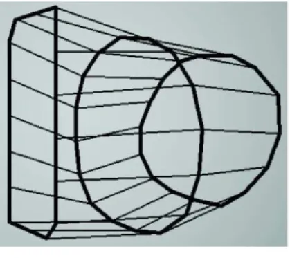
selection volume while remaining easy to control, fast and accurate. The selection process consists in creating a cylinder-like shape through the sequential definition of several adjustable sections, until the whole target is enclosed. This process results in the creation of a highly customizable 3D envelope, the adaptative envelope (cf. Figure 1), that defines the selection volume: each point of the 3D point cloud inside this envelope is selected.
Figure 1. Example of a selection envelope
created with the Worm Selector: it is composed by 3 contours of distinct shapes, drawn in non-parallel planes. Any point inside the envelope will be selected.
We first review existing selection approaches valid for complex and unstructured point clouds. Next we introduce the design properties of our interaction technique and describe its use and implementation. We then compare the Worm Selector with two other types of technique: the first, called Parallel Contours Selector, is inspired from a selection technique widely used in medical context and based on the use of parallel planes, while the second, called the Sphere/Cuboid Selector, is a well-known technique based on the use of simple and predefined selection volumes. Through these experiments we demonstrate how fast and accurate the Worm Selector is, compared to these two techniques. After a discussion on the benefits and limits of the Worm Selector we illustrate its use on three different case studies and finally conclude with the identification of a set of perspectives. Our contributions include 1) the design and implementation of an original interaction
technique for the selection in a 3D point cloud, 2) a comparison with two interaction techniques widely used in 3D environments and 3) an illustration of the use of the Worm Selector in three concrete and complex situations.
II. RELATED WORKS
Selection in a 3D point cloud is difficult for a user because there are only points and no surfaces. As a result, and because of the depth perception issue, two points displayed close to each other on a screen can in reality be far away from each other. Therefore, adjusting the camera viewpoint or adopting specific rendering techniques is required. Appropriate rendering techniques exist [11] but are out of scope of this paper. Therefore, in this section we focus on solutions that support the control of the camera viewpoint and selection of a 3D point cloud subpart.
2.1 Ray Based Selection.
Ray-casting is a classical technique from the literature to perform a mesh selection [21]. It has the advantage of being simple and intuitive [13]. It also maintains the technique complexity low, because only a mouse click on the screen is needed to launch a ray. It is however difficult to transpose this technique to point cloud because of the lack of surface: while pointing a surface is possible on a wide target zone, pointing one point of the point cloud requires an extreme accuracy as it must reach the exact coordinates x, y and z. To adapt its use in a 3D point cloud, Veit and Capobianco use an octree to predefine boxes in the point cloud; a ray casting is then used to select the box that contains the desired points of the point cloud [23], among the boxes created by the octree. The limit of this approach is that it results into the selection of a set of points (those included in the selected octree-leaf) that are not necessarily all part of the subpart the user is trying to select. Others, like Cashion and LaViola [9], replaced the ray by a cone. The projection of a cone allows a simpler selection of points in a 3D point cloud because the created selection volume easily encloses the targeted points. However, it also results in a less accurate selection
because the cone will include unwanted points: accuracy vs. ease of use is not a problem per se, but when using a cone-based selection, this compromise must be known and accepted by the user. To offer more flexibility to these techniques, additional control can be added to the selection volume. The previously mentioned work allows to control the aperture and orientation of the cone only. To offer more flexibility to the selection, Lucas et al. propose to manually draw any closed shape on a screen instead of the regular circle corresponding to the base of a traditional conus [14]. The shape is projected in the 3D scene depth (thus creating a cylinder if a circle was drawn), selecting every point inside. Yu et al. proposed a similar technique [26], but only as a start to look for areas with density higher than a specified threshold. This approach is not possible for an unstructured point cloud, where the density is not representative of the represented object: it depends on the distance of the scanner to the scanned surface.
2.2 Volume Based Selection.
To keep the complexity of use at a low level led [7] to rely on a very simple solution: the use of a fixed volume. The volume is attached to the virtual camera that provides the point of view on the 3D environment, therefore when the camera is moved the volume moves to stay at the same relative position. Besides making difficult to anticipate what is selected, multiple adjustments are required to obtain the desired target.
In order to enhance this solution, the volume can be parameterized. As a result, the selection can better match the target. For example Ulinski et al. [22] as well as Lucas et al. [14] proposed an interaction technique to control a cuboid orientation and size. Ulinski proposed to control two points from a cuboid diagonal with two hands: moving the hands in the physical space moves the points in the virtual environment. Lucas used a 6 DOF wand to control either the position and orientation or the shape of the cuboid, depending on the buttons a user pressed. Despite the limited number of parameters of a sphere, Benko and Feiner [4] and Naito et
al. [15] used innovative interaction techniques to control its position and size when selecting part of a 3D point cloud. The first one, the Balloon selection, involves a touch surface representing the ground of the visualized 3D point cloud to control the position and size of the selection sphere, i.e. a sphere used to select the elements of the 3D scene. The second involves a physical cylinder as an input surface. The point cloud is represented inside and the size and position of the selection sphere is deduced from the user's finger positions on that cylinder. Beyond spheres and cuboids, Krammes et al. used an ellipsoid [12]. The shape is controlled by orienting a smartphone to select the axis to modify, and then sliding a finger on the screen to modify the shape along this axis. These new shapes offer more control over the selection volume than a ray casting technique, especially in depth. However, the predefined shapes remain simple to use, offer a limited set of parameters to be adjusted and are necessarily predefined to preserve their ease of manipulation. In addition, they do not support an easy and rapid selection of irregular volumes: indeed, boxes are very well suited to select angular objects, spheres are perfect to select spheres, but a combination of multiple predefined forms is required to select an irregular object such as a hand, an organ. Combining multiple predefined shapes to match such an irregular object will take time and will result in false-positive and false-negative selected points because the contour of the predefined shapes cannot fit exactly the contour of the targeted object.
2.3 Free-form Objects.
To select a 3D volume, instead of combining predefined shapes, an alternative consists in using free form shapes. Free-form shapes offer a greater freedom to increase the precision of the selection volume. Several works have explored this solution and the key challenge appears to be the way the free-form shape is built by the user.
Blenders [5], one of the commercial softwares supporting the free-form shape selection mechanism, is a good example.
However, its use is based on a very complex graphical interface. To avoid this difficulty, Kang et al. explored the use of a predefined set of hand gestures [10] to adjust the free-form shape. It also remains complex as there are more than twenty gestures to learn. Instead of defining the free-form shape explicitly, another approach consists in specifying constraints on the free-form shape and its attributes. For example, one can constrain the shape to be a sphere, limit its modification to a change of the radius only, although more freedom could be added by changing it to an ovoid. While it limits the editing possibilities, the benefits of such approaches is that it also greatly simplifies the interaction required to control the free-form shape selection mechanism. Vinayak et al. [24] combined this approach with a gesture based interaction to control the technique: as a result hand gestures appear to be much simpler than those used in Kang et al. [10], but the counterpart is that the free-form shape is limited to a generalized cylinder. The problem is again a question of compromise between interaction simplicity and flexibility of the offered technique. To reach a better compromise, a common approach in the medical field consists in identifying the 2D contour of the target from different points of view. Such an approach is commonly used on a set of slices (array of images) [2]. However, it only involves contours drawn on different parallel planes along a unique axis. To overcome this limitation, alternatives have been explored but are dedicated to voxel inputs [19]. Volume selection is thus facing a trade-off between flexibility, accuracy and ease of use. On one hand, “ray/cone casting” techniques are very easy to use. They offer some flexibility (orientation, aperture) to the detriment of accuracy. On the other hand, free-form shapes have the greatest potential of accuracy because they can be tuned to perfectly match the targeted shape; but their use appears rather complex due to too many degrees of freedom in their manipulation. In between, predefined shapes are easy to manipulate and can be adapted but only to a
limited extent (mainly scaling). Our work aims at designing an interaction technique that would combine the advantage of the free-form shapes while keeping the ease of use of the predefined shape-based techniques. We therefore designed a selection technique that is based on the definition of multiple 2D free-form contours, automatically linked together. Drawing a contour and automatically linking them ensure the simplicity of use; free-form contour ensures the flexibility of the selection form and contribute to the accuracy of the selection.
III. DESIGN PROPERTIES OF THE WORM SELECTOR 3.1 Overview.
The Worm Selector is intended to be used by anyone (expert or not) on a regular computer to select a set of points in a 3D point cloud, corresponding to a “complex” shape. We define a “complex” shape as a shape that cannot be easily selected with existing and standard volume based selection techniques using a sphere, a cube or a cone. The Worm Selector is thus intended to be well suited for the selection of irregular volumes such as a rusted area, combinations of different volumes (for example a cylinder in a dome that represent a telescope) or volumes not corresponding to frequently used geometrical shapes such as pyramids, trapezoid, etc. The idea behind the development of our technique, the Worm Selector, is to allow a simple and yet effective selection based on an
adjustable shape while keeping the
constraints as low as possible. To offer a compromise between simple 3D shapes not fitting well the targeted volume and free-form 3D shapes too hard to control, our approach consists in building an adaptative envelope, the worm, so that it closely matches the targeted volume. In the medical field, the regular approach is to draw 2D contours on successive parallel planes. Our approach is similar but adds a feature allowing to modify the orientation of the plane to remove the restriction of using only parallel planes.
3.2 How to use the Worm Selector.
Figure 2 shows an example of the progressive use of the Worm Selector for constructing the selection envelope. It shows an envelope made of three freely drawn 2D contours linked together by straight lines to create a volume. On this figure, the contours are all different and the third one is drawn in a plane that is not parallel to the two others. Despite being a very simplistic illustration, this figure highlights the two major facets of the Worm Selector: use of multiple and different contours, positioning of the contour in totally freely defined planes. We detail the use of the
Worm Selector in the following 3
subsections: creating the contours,
connecting them and finally selecting the points.
Figure 2. Progressive building of the
selection envelope with the Worm Selector. (a) First contour drawn. (b) Second contour created with a different right angle; connected to the first one it forms one section of the envelope. (c) Third contour drawn with a different orientation; its connection to the second contour extends the envelope.
A) Creating a contour.
Drawing a contour is done on the so-called
“drawing-plane” which position and
orientation can be adjusted independently of the camera viewpoint (Figure 3b). We chose to keep the manipulation of the drawing-plane separated from the camera because of the depth perception problem (section 2). Once the drawing-plane is positioned at the targeted spot, the camera viewpoint can automatically be adjusted so that it faces the drawing-plane (Figure 3c). A contour can then be manually drawn on the drawing-plane around the visible section of the targeted volume. As each contour is drawn on the drawing-plane, i.e. a 2D plane, using a regular mouse is sufficient and therefore the
Worm-Selector does not need a dedicated or any 3D specific input device to be controlled. a) b) c)
Figure 3. Using the Worm Selector:
visualising the 3D scene (a), adjusting the drawing-plane (b) and drawing a contour (c).
There is no constraint on the form of the contour. It can be a convex contour or a concave one, it may be polyhedron or a simple shape like a square or a circle.
B) Connecting the contours.
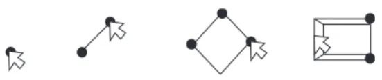
Figure 4. Linking two contours of the Worm
Selector: (a) Computing 3D coordinates for each point of the 2D contour; (b) sampling the contour into a predefined number (360 by default) of 3D points; (c) linking each of the 360 points of two successive contours.
In order to link a new contour with the previous one, several steps are required. First, a contour is in fact a set of pixels that has been defined on the drawing-plane; we thus need to convert each pixel into a 3D point whose coordinates are expressed in the overall 3D scene (Figure 4a). Second, we compute the total length of the contour in order to discretize it into a predefined number of points regularly distributed on the contour (Figure 4b); this number has to remain constant over the different contours, otherwise linking two contours becomes far more complex. By default, this number is fixed to 360 but it can be adjusted by the user before using the Worm Selector: this number of course affects the accuracy of the resulting envelope. Third, we calculate the normal of the new contour and compare it to the previous contour: identifying the normal direction for the two contours is required to decide whether the new contour must be scanned clockwise or counter-clockwise and thus avoid malformed volume when linking the two contours. Fourth, we identify the starting point of the linking through the identification of the point of the contour that is the highest and the furthest away from the contour centre. Fifth, we draw a straight segment between the starting point of the two contours and repeat this operation for the 359 remaining points that define each contour (Figure 4c). Except in limited cases, this algorithm leads to a soundly defined volume. Interactive adjustments of the starting point (step four) are also supported to avoid the
Selection volume
Target volume
Shortcuts:
Turn the cube
1 : Switch to Edit mode W : Delete any selection X : Delete the last contour D : Hide/Show the Worm
Target:
Drawing plane
Shortcuts: Target:
1 : Switch to View mode 3 : Switch to Draw mode C : 180° rotation of the Drawing-Plane R : Reinitialize
Drawing-Plane position W : Delete any selection X : Delete the last contour D : Hide/Show the Worm
Contour being drawn
Shortcuts: Target:
3 : Switch to Edit mode
Shortcuts:
creation of a twisted extension to the envelope: this may occur with specific contours such as V-shape contours.
Even if two successive contours intersect, an
extension is soundly built. When
intersections exist in the envelope created with the Worm Selector, the overall envelope will look like a "folded cylinder", as illustrated on Figure 5 – left. We do not encourage such cases as it may be difficult to anticipate and understand the real form of the 3D envelope created.
Figure 5. Illustration of a "folded cylinder" (made of 4 contours) obtained if two successive contours intersect (left) and a "self-intersecting envelope (right). Built with Blender for sake of clarity.
C) Selecting the points.
The main problem of having a free-form shape is to determine whether a point is inside the shape or not. To do that, we use a simple algorithm that works for any closed mesh and therefore is relevant for the Worm Selector. Concretely, as soon as an extension is added to the envelope, a ray is cast from each unselected point of the point cloud. Previously selected points are just ignored by this algorithm, thus remaining selected. If the ray encounters an odd number of faces of the worm, then the point is inside. It is however computationally expensive as it must be done for each point. To keep our algorithm real time, the computation is done on the GPU with OpenGL compute shaders. The GPU being highly parallelized, there is one “thread” per point and the computation is done more quickly. This computation occurs only when a contour is completed; in addition our mesh, the worm, contains a relatively small number of faces (360 by default between each pair of contours); therefore no
further improvements of the algorithm was required. Alternatively, we could have used an accelerating structure like an octree to store the worm points; such optimisation will be considered in future work.
Deselecting an already selected point requires deleting the extension of the envelope in which this point is included. To do so, the user has to delete the contour that triggered the creation of the extension. Adopting such a process ensures that even if the position of a new contour triggers a self-intersection of the envelope (see Figure 5 – right), already selected points will remain selected.
D) Summary.
Using the Worm Selector technique thus relies on successive iterations of a 2-step process:
1) placing the drawing-plane at the desired location and orientation in the point cloud; 2) drawing a 2D contour on that plane. As a result of this second step, the new contour is automatically linked to the previous one, a new extension is added to the previously built envelope and finally, every point inside this new extension of the envelope becomes selected. Deselecting points requires to delete the corresponding envelope extension. When the last contour is created, validating the created envelope finalizes the worm definition. Through the successive iterations of this process, several contours are created and linked. Two consecutive contours may of course be of different shapes (as illustrated in Figure 2 c). The envelope is therefore progressively built: linking a new contour to the previous one extends the previously built envelope.
A worm is thus made of a minimum of two contours and is not limited by a maximal number of contours. The shape is similar in principle to the generalized cylinder from [24]. However, in our case, it is defined by a succession of points connected by straight lines instead of formulas.
IV. INTEGRATING THE WORM SELECTOR IN AN APPLICATION
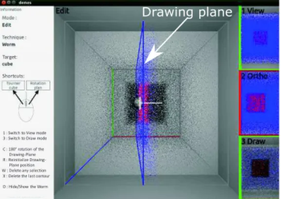
To illustrate the Worm Selector behaviour, we integrated it in a 3D rendering application used to visualize and navigate in a 3D point cloud. It includes different interface elements on each side of the main window to provide assistance to a user. This implementation is a generic implementation that could be inserted in any open-source application dedicated to the display and control of 3D point clouds. In the description below, we also include the description of the feedback that will be provided by the application supporting the user’s study. Except when an explicit mention is provided, all the features and feedback mentioned below are required in any generic implementation of the Worm Selector.
To create the envelope of the Worm Selector three different interaction modes are offered to the user: the view mode, the edit mode and the draw mode. Each mode offer a predefined set of interactive features, as summarized in the state diagram (Figure 6).
Figure 6. State diagram depicting the
different modes of use of the Worm Selector (view, edit, draw) and the associated features.
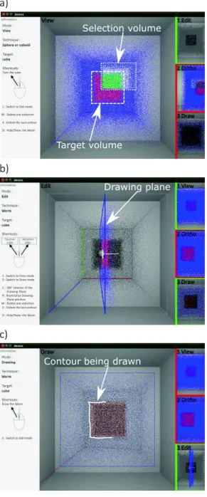
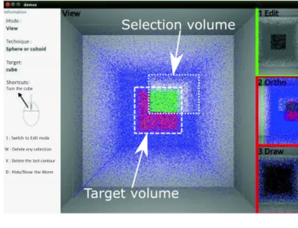
When using the Worm Selector, the user perceives the current mode in the centre of the interface, a set of reminder (including the current keys available for example) on the left of the interface and, a preview of the two other modes on the right of the interface (see Figure 7). We describe in the following paragraphs for each of the three interaction modes, how the Worm Selector is built and controlled through the features offered. The view mode (Figure 7) supports the visualization of the 3D scene and the targeted
volume, as well as the current selection if one exists.
The colour code used in this mode is green for the points that are selected and blue for the others. Additional colours (red and white) were used exclusively for the experiment and are described in the users experiment section (section 5.1.1).
The only interactions offered in this mode is to rotate the camera and to change the mode to “edit”.
Figure 7. Using the Worm Selector: View
mode of the application used during the user's experiment.
The edit mode (Figure 8) supports the visualization and manipulation of the drawing-plane.
The colour code used in this mode is the same than in the previous mode. However, to help the user performing an accurate selection, this colour code is only applied to the points situated on one side of the drawing-plane and below a user’s adjustable distance to the drawing plane. It thus limits the perception of the 3D point cloud to the points that really matters in order to decide how and where to draw the current contour. All the other points are displayed in grey. During the experiment, the other points that were part of the targeted points were represented in black.
This mode offers again the possibility to rotate the camera. It also offers the ability to control the drawing-plane, by translating it along the vector representing its normal direction (represented in white on the Figure 8), or rotating it according to its two angles
Selection volume
Target volume
Shortcuts:
Turn the cube
1 : Switch to Edit mode W : Delete any selection X : Delete the last contour D : Hide/Show the Worm
(the centre of rotation being the origin of the vector representing the normal to the plane). The side of the drawing-plane where the points are coloured can be changed, and a reset function is provided to put the drawing-plane back to its default position and rotation. Other controls over the selection volume are available too, such as deleting the whole selection volume or only the last contour added (or the last two if pressed twice, and so on). It is finally also possible to hide the selection volume, in order to display the points only, or show it. Finally, from this mode it is possible to move towards the view mode or the drawing mode.
Figure 8. Using the Worm Selector: Edit
mode of the application used during the user's experiment.
The drawing mode (Figure 9) allows the drawing of the contour on the drawing-plane, The user should thus enter this mode only once an appropriate position of the drawing plane has been defined so that the targeted object is visible in the drawing plane. The camera on this mode is always placed so that the view-plane is parallel to the drawing plane. In addition, any already drawn parts of the worm are hidden to prevent hiding the target.
The only available interactions in this mode are to draw a contour or to go back to the edit mode. Moving the mouse while pressing the left button draws a contour freely, like with using a pen on a paper. Alternatively, a mouse click (press + release) defines the origin of a straight line drawn between this
origin and the mouse cursor; a second mouse click terminates this segment. A succession of straight lines can therefore be used to build the contour and avoid hand tremor. The two approaches can of course be combined to create a contour made of straight lines and freely drawn sections.
i.e. a 2D plane.
Figure 9. Using the Worm Selector: Draw
mode of the application used during the user's experiment.
Finally, terminating the definition of the contour is validated with a double mouse click.
V. USER EXPERIMENTS
In order to assess the usability of the Worm Selector, we considered two complementary indicators [8]:
- performance, with quantitative metrics such as time and errors, and
- user’s preference, with qualitative metrics such as the best and worst aspects of each technique and the system usability score (SUS [3]).
To achieve this usability assessment, we performed two complementary user studies. These two studies shared a set of elements that we introduce in this section. We then further detail each experiment and present the associated results in sections 6 and 7. The goal of the first experiment is to compare the Worm Selector to a selection technique widely used in the field of medicine [2]. In medical context, 3D models are made of
Drawing plane
Shortcuts: Target:
1 : Switch to View mode 3 : Switch to Draw mode C : 180° rotation of the Drawing-Plane R : Reinitialize
Drawing-Plane position W : Delete any selection X : Delete the last contour D : Hide/Show the Worm
Contour being drawn
Shortcuts: Target:
3 : Switch to Edit mode
Shortcuts:
slices of data along one given axis. The contours can thus be defined on each parallel slices, then linked to obtain a free form envelope. As opposed to this approach, when using the Worm Selector, contours can be drawn in planes that are not necessarily parallel planes. The goal of the first experiment is thus to establish whether drawing contours on non-parallel planes makes the use of a contour based selection technique more complex or not. To this end we implemented a second interaction technique, named Parallel Contours Selector. Section 6 describes in detail this technique and the experiment.
The goal of the second experiment is to compare the Worm Selector to the most widely used type of selection technique in the 3D domain (see Section 2 or existing software such as CloudCompare [1]): a selection based on a simple and predefined 3D volume. The goal of this second experiment is thus to establish whether the Worm Selector preserves the accuracy and is easier to use than an approach based on
predefined volumes. Commonly used
predefined volumes in the literature are the sphere and the cuboid which lead us to the design and implementation of a third
interaction technique, named the
Sphere/Cuboid Selector: it allows the definition of an envelope made of several spheres, cuboids or any combination of them, each being adjustable in size, position or orientation (see Section 7.1). Advanced interaction techniques such as mid-air solutions have been avoided as they bring fatigue and are not yet established as reference to build a 3D model.
5.1 Experimental settings.
A) Apparatus
In both cases the experiment was performed on a PC running Ubuntu 14.10 64 bits, with one AMD FirePro M4000 graphics card. One display output was connected to a 24 inches screen (1980 × 1080 resolution). A keyboard
and a simple mouse with two buttons and a wheel were used as inputs.
The volume selection takes place in a 3D scene made of a simple cube of points and displayed in a 3D grey environment. For the two experiments the 3D scene can only be rotated around its centre, no translation or zoom were supported. The point cloud has been manually generated. It is made of points that are regularly distributed in space, with a small random shift avoiding a too perfect alignment that would affect the perception. During the experiment, we extended the colour code used in the initial integration of the Worm Selector in an application (see Section 4). Initially limited to green and blue (see Figure 7), we added the red and white colours to provide additional feedback during the experiment.
- The targeted points are red to clearly render the non-conventional 3D volumes used during the experiment. All the other points of the 3D point clouds remain blue. - The selected points that are part of the
targeted ones (positive points) are green and the false-positive were white. This additional feedback was exclusively provided during the user’s experiment to highlight the 3D volume to select and the result of the selection. This extended colour code ensures that the participant can perceive at any time the form of the envelope that has been built; furthermore, having a clear distinction between the selected points that are part of the target and the others ensures that the participants maintain a clear view and understanding on the 3D form to select. Without this extended colour coding system, the instruction to the participant would have been to select an object of the 3D point cloud. Therefore, an empty space around this object would have been required, thus preventing us to measure the potential of our technique in terms of accuracy.
B) Target definition
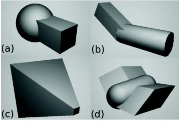
The targeted volumes correspond to unconventional and irregular shapes as defined in Section 3.1 (Figure 10).
The first two shapes (Figure 10 a and b) were used for the training. The first one, the
“sculpture” (Figure 10 a) is simply composed of one sphere and one cuboid joined together. It allowed participants to learn to draw a contour fitting the changing Section of the target volume. The second one, the “L” (Figure 10 b) is made of a cuboid and a cylinder aligned along different axes. It was designed for learning how to manipulate the drawing-plane and its rotations.
Figure 10. The shapes to select: (a) the
Sculpture, (b) the ‘L’, (c) the Pyramid and (d) the Welding.
The two remaining shapes were used during the real experiment, following the training period. The “pyramid” shape (S1), is a pyramid with its top cut, that is to say not corresponding to classical volumes (Figure 10 c). Finally, the other shape used for the study, the “welding” (S2), is a combination of three parts, two trapezes aligned along different axes connected by a rounded cylinder (Figure 10d), thus figuring welded elements.
C) User’s task
The task consisted in selecting a predefined set of points in the scene that together represented one of the four volumes described above. Participants were instructed to select the targeted points as accurately and quickly as possible.
5.2 Procedure and collected data.
Participants started with a training session for each selection technique. Participant had to select each shape three times (always in the same order, the “sculpture” then the “L”). Once the training for a technique was over, the participant moved on to the controlled
experiment aiming at the selection of the target shape with the current technique. When starting with a new shape, a representation of the shape, with the surface only, was presented to the user (as on Figure 10). It allowed to clearly perceive the shape to select. The participant was only allowed to rotate the camera view for as long as required. Once the participant agreed, the selection started and this initial representation was no longer available.
Each time a participant began a selection, the camera and drawing-plane were put in their default position and orientation. Each time the participant validated a selection, no target was displayed afterwards. This allowed the participant to take a break if needed. The next target was made visible (and the time being tracked) at the request of the participant. We measured the completion time of the training and of each trial. We recorded the envelope or spheres/cuboids created to select the volume in order to enable the computation of:
- the precision percentage (proportion of the selected points that are effectively part of the targeted volume),
- the recall percentage (proportion of the targeted points that are effectively selected) and,
- the amount of contours / spheres / cuboids that forms the selection volume created. Hence, the amount of over-selected points can be deduced from the precision percentage; and the recall percentage represents the accuracy of the selection. We also collected user preferences through a ranking of the two techniques at the end of the experiment. Finally, we asked for both techniques, the three best and worst points; as
a complementary indicator to these
subjective comments, participants filled a SUS questionnaire.
VI. COMPARING THE WORM SELECTOR AND THE PARALLEL CONTOURS SELECTOR
6.1 The Parallel Contours Selector at a glance.
The Parallel Contours Selector technique we implemented is quite similar to the Worm Selector technique. The only difference is that the drawing-plane cannot be rotated. Otherwise both are based on creating a selection volume by successively drawing free formed contours and automatically connecting them with straight lines as described in Section 3.
6.2 Participants and Design.
Twelve participants (5 females and 7 males), aged 29.2 years old (SD = 5.0) on average were recruited. All were using a computer every day, and were at least familiar with 3D environments, i.e. able to understand a 3D scene.
This study follows a 2×2 between-subjects design with interaction techniques and target shapes as factors. Two selection techniques were considered: the Worm Selector (T1) and the Parallel Contours Selector (T2). Two different shapes to select were used: the pyramid (S1) and the welding (S2).
The study is made of 4 blocks. Each block is made of a first pair of technique and shape followed by a second pair involving the other technique and the other shape (T1-S1 / T2-S2, T1-S2 / T2-S1, T2-S1 / T1-T2-S2, T2-S2 / T1-S1).
Each participant is involved in only one block. Participants of different blocks were therefore exposed to the two interaction techniques and the two shapes, but participants of different blocks were not confronted to the same pair of technique and shape. Blocks were counterbalanced over participants and three participants performed each block.
This design was created to avoid a learning effect and to reduce the already long time each participant had to spend on the experiment (100 minutes on average). Each participant thus had to accomplish a total of two interaction techniques × 1 shape
(per technique) = 2 volume selections (without the training). Overall for the experiment 12 participants × 2 selections = 24 selections have been made (without the training).
6.3 Results.
In the collected data, no significant difference nor tendency has been measured between the two techniques for the recall, the precision or the time. In addition, the Worm Selector has been largely preferred (10 out of 12 participants) to the Parallel Contours Selector. This is an interesting result because the Worm Selector offers more degrees of freedom than the Parallel Contours Selector thus potentially raising the complexity of its use. Despite that and the lack of difference between the two techniques in terms of performance, users preferred the Worm Selector. This might be due to a higher feeling of freedom when using the Worm Selector, which encourage deepening the assessment of the Worm Selector.
For that reason, and because some shapes (e.g. a torus) cannot be selected with it, the medical technique has not been kept for the second experiment.
VII. COMPARING THE WORM SELECTOR AND THE SPHERE/CUBOID
SELECTOR
7.1 The Sphere/Cuboid Selector at a glance.
In this second experiment, two selection techniques are used: the Worm Selector (described before) and the Sphere/Cuboid
Selector. The Sphere/Cuboid Selector
consists in building an envelope (as with the Worm Selector). However instead of using a set of connected free formed contours the envelope is made of a set of spheres and cuboids, two shapes that are often used in the literature [4][7][12][14]. Therefore, the behaviour of the Sphere/Cuboid Selector differs from the behaviour of the Worm Selector when the drawing mode is activated. In the drawing mode, pressing the right mouse button draws the first point of a sphere on the drawing-plane (Figure 11). The
diameter of the sphere is then defined from the initial point to the current position of the cursor. Releasing the button validates the creation of the sphere.
Figure 11. Defining, in the Drawing mode, the
centre and size of a selection sphere to be added to the envelope.
Alternatively, pressing the left mouse button defines a corner of a cuboid (Figure 12). The mouse can then be moved in the drawing plane. Releasing the button defines one side of a rectangle. Repeating the operation allows to define the height of this rectangle. At that point the camera will automatically be moved to align itself with the cuboid depth axis. The last step consists in moving the mouse to adjust the depth of the cuboid and validating with a left click. The camera goes back to the correct position and the cuboid is validated.
Figure 12. Defining, in the Drawing mode, the
contour and depth of a selection cuboid to be added to the envelope.
Several contours (with the Worm Selector) or spheres and cuboids (with the Sphere/Cuboid Selector) can thus be drawn to define the selection volume.
7.2 Participants and Design.
Sixteen participants (14 males and 2 females), aged 30.3 years old (SD = 6.56) on average were recruited. All were using a computer every day, and were at least familiar with 3D environments, i.e. able to understand a 3D scene.
This study follows a 2×2 between-subjects design with interaction techniques and target shapes as factors. Two selection techniques were considered: the Worm Selector (T1) and the Sphere/Cuboid Selector (T3). Two different shapes were used to define the target
volume: the pyramid (S1) and the welding (S2) as in the first experiment.
The study is made of 4 blocks. Each block successively involves two pairs of technique and shape as in the first experiment (T1-S1 / T3-S2, T1-S2 / T3-S1, T3-S1 / T1-S2, T3-S2 / T1-S1). The use of each pair is repeated three times successively.
Each participant is involved in only one block. Participants of different blocks were therefore exposed to the two interaction techniques and the two shapes but not in the same order and not with the same pairs of
technique and shape. Blocks were
counterbalanced over participants and each were performed by four participants.
Each participant thus performed a total of 3 repetitions × 2 interaction techniques × 1 shape (per technique) = 6 volume selections (without the training). Overall for the experiment 16 participants × 6 selections = 96 selections have been made (without the training).
7.3 Results.
In the following sections, we present the quantitative and qualitative results we obtained. Details about the statistical tests used can be found n [18].
A) Quantitative analysis
For each statistical analysis, we used Shapiro-Wilk tests to verify the normality of data and then choose the appropriate statistical test between parameterized (AOV) or non-parameterized (Wilcoxon and T tests). Wilcoxon or T- tests confirmed that our protocol did not incur any bias towards one technique or group. We did not find any statistically significant difference in the three measurements (precision, recall and time) used in this study between interaction techniques and shapes:
- user starting with the Worm Selector (T1) and those starting with the Sphere/Cuboid Selector (T3) perform similarly
- user starting with the pyramid (S1) and those starting with the welding (S2) perform similarly as well.
A Kruskal-Wallis test confirmed that there was no significant difference between the
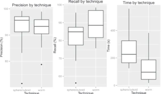
four groups. We can thus analyse the measures from the four groups together. On average we observed that the selection with the Worm Selector was significantly faster (133s, SD = 121) than with the Sphere/Cuboid Selector (266s, SD = 154) which was confirmed by a Wilcoxon test (p=3.9×10⁻²). There was no significant difference for the precision (worm: average = 92%, SD = 5.6; sphere/cuboid: average = 93%, SD = 9.4) or the recall (worm: average = 88%, SD = 8.7; sphere/cuboid: average = 82%, SD = 11). The results can be visualized by quartiles on the Figure 13.
We also noticed that there is a significant difference on the number of parts drawn (p=1.2×10⁻³): the number of parts drawn corresponds to the number of sections for the Worm Selector (average = 4.4, SD = 2.4) and to the number of spheres and cuboids for the Sphere/Cuboid Selector (average = 13.5, SD = 7.4). However we did not observe any significant change in the number of parts drawn over trials for the Worm Selector (Friedman test, χ²(2)) or the Sphere/Cuboid Selector (AOV, F(2,30)=0.78).
Figure 13. Precision, recall and time results
obtained for the Sphere/Cuboid Selector technique and the Worm Selector. These results include the selection of the pyramid (S1) and the welding (S2).
When focusing the analysis of the results by shape, we observed that the Worm Selector allows for a highly improved selection of the pyramid (S1) compared to the Sphere/Cuboid Selector. The technique is significantly faster (p=2.1×10⁻⁴; worm: average = 42.9s, SD = 17.2; sphere/cuboid: average = 191s, SD = 63.0) and leads to a better recall
(p=4.7×10⁻³; worm: average = 95%, SD = 5.4; sphere/cuboid: average = 84%, SD = 6.5). No significant difference is observed for the precision (worm: average = 95%, SD = 2.2; sphere/cuboid: average = 92%, SD = 9.3).
No significant difference is observed between the two techniques regarding the selection of the welding (S2). There is only a tendency in favour of the Sphere/Cuboid Selector on the precision (p=6.5×10⁻²; worm: average = 89%, SD = 5.3; sphere/cuboid: average = 94%, SD = 4.6), and a tendency in favour of the Worm Selector on the time (p=7.6×10⁻²; worm: average = 224s, SD = 97.9; sphere/cuboid: average = 342s, SD = 143). No tendency is observed regarding the recall (worm: average = 82%, SD = 5.6; sphere/cuboid: average = 80%, SD = 12). The results for the welding can be visualized by quartiles on the Figure 14.
Figure 14. Precision, recall and time results
obtained for the Sphere/Cuboid Selector technique and the Worm Selector technique for the welding shape only
As the participants had to repeat three time the same selection with the same interaction technique, we also compared the results by considering only the first trial of each technique, without distinguishing the shapes. The goal is to study how newcomers really behave when they discover these interaction techniques. We observed that the Worm Selector is significantly faster (p=7.6×10⁻³; worm: average = 162s, SD = 154; sphere/cuboid: average = 342s, SD = 168). The recall measured is significantly higher for the Worm Selector, meaning that the
80 90 100 sphere/cuboid worm Technique P re ci si o n (% ) Precision by technique 60 70 80 90 100 sphere/cuboid worm Technique R ec al l (% ) Recall by technique 0 200 400 sphere/cuboid worm Technique T im e ( s ) Time by technique 80 85 90 95 sphere/cuboid worm Technique P re ci si o n (% ) Precision by technique 60 70 80 90 sphere/cuboid worm Technique R ec al l (% ) Recall by technique 100 200 300 400 500 sphere/cuboid worm Technique T im e ( s ) Time by technique
technique selects more of the target points (p=1.1×10⁻²; worm: average = 86%, SD = 9.8; sphere/cuboid: average = 77%, SD = 11). However, in terms of precision no significant difference were observed (worm: average = 92%, SD = 4.6; sphere/cuboid: average = 94%, SD = 4.1).
B) Qualitative analysis
Two aspects have been considered in the qualitative evaluation: usability and user preference.
Usability evaluation. The SUS questionnaire [6] gives an average score of 74.69 (SD = 17.67) for the Worm Selector. Its design is thus rated “good” and is considered acceptable in terms of usability (highest acceptability range) [3]. The Sphere/Cuboid Selector obtains a score of 59.38 (SD = 15.82). Its design is noted “OK” in terms of usability and its acceptability is marginal [3]. A Wilcoxon test shows that the SUS difference is statistically significant between the two techniques (p=9.6×10⁻³).
User preference. At the end of the
experiment participants had to indicate their preferred selection technique over the two techniques. The results are in line with the SUS scores: the Worm Selector is largely preferred as only one of the sixteen participants chose the other techique. Finally, we asked all participants to determine 3 positive and 3 negative points about both techniques.
The most recurring positive points mentioned concerning the Worm Selector were “fast”, “accurate” and “easy to use”. The negative points that were most often mentioned were “inaccurate”, “requires a good vision of space” and “unadapted to spheres, wave and the like”. The last comment is about rounded objects. It is true that if the object is round in more than one dimension, it then requires to use more sections to remain accurate as each section is linked by straight lines. If it is only in one dimension, like for a cylinder, the Worm Selector will then have no difficulty since a circle is relatively easy to draw.
The most recurring positive points mentioned concerning the Sphere/Cuboid Selector were “simple”, “fast to learn” and “predictable”. The most frequently cited negative points were “not enough predefined shapes (such as the sphere)”, “inaccurate” and “need to accurately place the drawing-plane”. We noticed a frustration when the target shape did not match with either a cuboid or a sphere, resulting in asking for more shapes to match all cases. However, increasing that number would also mean increasing the complexity of use of the technique.
The analysis of the most frequently mentioned positive and negative points reveals that the participants made comments about the results obtained when manipulating the Worm Selector, while they made comments related to the use when manipulating the Sphere/Cuboid Selector. Participants were thus more engaged with the task and their goal when using the Worm Selector than when using the Sphere/Cuboid Selector, as they were focusing on the result to reach and not constrained by issues related to the interaction technique.
7.4 Discussion.
Among the two selection techniques, the Worm Selector is not only better perceived but also offers better performances. A possible explanation to that may reside in the difference of the number of parts drawn. Indeed, the Sphere/Cuboid Selector requires a higher number of parts to be drawn, which could explain the significant difference in time taken to perform a selection. More time required and more parts drawn contribute to increase the discomfort and thus result in the Worm Selector being largely preferred by the participants.
In addition, the number of parts drawn does not vary significantly over trials involving the same shape to select. It means that once a user chooses a way to select, he is likely to stick to it. The first selection is thus very important and the Worm Selector showed that it was the best for that, selecting more target points and being faster with no significant difference in precision. The results also establish that newcomers or occasional users of the
technique can successfully use it right at the first trial.
During the experiment we used a perspective projection to render the 3D scene. It created difficulties to perceive precisely the position of the drawing-plane; as a result, it affected the perception of where the participant was drawing. It may be in part responsible for the inaccuracy the participants pointed out in the negatives points. A solution would be to use an orthogonal projection. It allows to keep parallel lines visually parallel but any information of depth is lost.
While the results establish that the Worm Selector shows great promises, the results also point that the selection performance is varying with the target shape. The pyramid shape shows this well; it is difficult to select with common selection volumes but very easy with our technique. In the same way nothing will select a sphere target better than with using a sphere selection volume. With the welding shape however, more complex, the differences are more blurred. The Sphere/Cuboid Selector shows a tendency to obtain a slightly better precision (1% better on average), while the Worm Selector tends to still be a lot faster (35% faster on average). There is no tendency observed for the recall. While the Sphere/Cuboid selector would be excellent for just a perfect sphere or a perfect cube, the worm selector demonstrates its ability to be applicable and robust with simple forms such as the pyramid or more complex forms such as the welding.
Further investigations will therefore be required to identify the exact settings in which the Worm Selector performs better (time, precision and/or recall). A more systematic definition and theoretical work on the characterization of a complex shape will thus be needed.
VIII. ILLUSTRATION OF THE USE OF THE WORM SELECTOR ON THREE CASE STUDIES
In this section, we illustrate the use of the Worm Selector in three realistic complex situations: a huge point cloud, a concave
object and a perforated object to select. The first case shows a potential real life usage of the Worm Selector. The two other ones demonstrate how a complex envelope can be built to select challenging 3D volumes.
8.1 The Telescope Bernard Lyot.
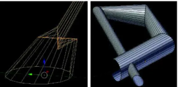
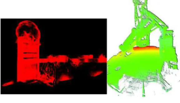
The first case study relies on a collaboration with the Telescope Bernard Lyot (TBL) situated on top of the Pic du Midi. The TBL is part of the Observatoire Midi-Pyrénées (OMP) research lab and is affiliated to the French National Research Center (CNRS) and the University of Toulouse. In order to create a database of the blueprints of all its buildings and to store a copy of their current state, the University of Toulouse has initiated a vast campaign in order to 3D scan all its buildings. The entire platform of the Pic du midi has thus been 3D scanned from the outside, including outside of the TBL (Figure 15-left). The inside of the tower in which the TBL is situated has also been 3D scanned to obtain a 3D point cloud of the telescope itself (Figure 15- right). This point cloud contains over 330 million of points.
Figure 15. The point cloud obtained through a
3D scan of the outside of the TBL (left) and of the inside of the tower in which the Telescope Bernard Lyot is installed (right).
Typically, the 3D scan of the telescope can be very useful to identify the modifications made to the initial equipment, simulate the insertion of new tools around the telescope or better visualize parts of the telescope that need to be replaced. In this specific context of element replacement, identifying the element in the 3D point cloud may rely on an automatic selection. Automatic selection would first need a criterion to be used: it may
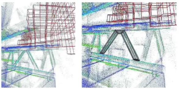
be for example the point density. This criterion is then used to determine whether a 3D area has to be selected or not. The form and shapes of this 3D area has to be predefined and therefore an automatic selection of a subset of the 3D point cloud results in a collection of predefined shapes (cubes in the Figure 16-left): as already mentioned accuracy vs. computing time is a compromise that must be optimised. But in this context, a lack of accuracy may have a dramatic impact on the decision taken, and a too long period of inactivity must be avoided as this equipment is unique in Europe and daily used by European research scientists. The Worm Selector technique could therefore be used as a complementary tool: an automatic rough selection could be quickly performed on the basis on point density for example, before being refined through the fine selection of the most appropriate section of the point clouds with the Worm Selector. Another limitation of the automatic algorithm is that no semantic information can be used. An yet, if one is interested in only one “arch” of the V-shaped structure supporting the telescope (see Figure 16), the Worm Selector will be useful to select only this part. Figure 16- left illustrates the result of an automatic selection based on the point density. In Figure 16- right, the illustration of use of the Worm Selector depicts the selection of the relevant part of the structure only (number of lines to connect two contours reduced to eight for sake of clarity).
Figure 16. Automatic selection of the area
containing a low density set of points in the 3D point clouds of the telescope (left) and Worm Selector based selection of an arch of the V-shaped armature supporting the telescope (right).
8.2 A concave object: the thick glass.
The second illustration has been chosen to demonstrate how a concave object can be selected with the Worm Selector.
The concave object is a thick glass, designed to keep its content warm. The goal is to select the glass, without its content and without the drinks coaster. We progressively describe how the contours should be drawn to enable the selection of the object with the Worm Selector. Graphical illustrations are provided in Figure 17: the point cloud on which the Worm Selector will be used, a real picture of the 3D scanned scene to better understand the scene and the form of the successive contours to be drawn.
The first contour will reflect the most external facet of the glass. As this one is rounded, a small rectangle or even a circle should be drawn on a plane that is tangent to the glass and vertically oriented (contour 1). The next contour should be a rectangle of the same height than the glass and placed just before the inside of the glass (contour 2). As the glass is a rounded object intermediate contours could be added between contours 1 and 2 to closely follow the rounded surface of the glass. The next contour should reflect the fact that the inside of the glass is concave: the contour should therefore be a “U-shaped” contour, of the same height than the glass (contour 3). As previously mentioned, the glass being a rounded object, several “U-shaped” contours of growing width can be successively created until reaching the diameter of the glass, materialized in Figure 17-left by the dotted line. At that point, half of the process of selecting the thick glass is done; the user proceeds similarly with the other half as illustrated with contours 4, 5 and 6 in the Figure 17.
Using only the six contours drawn in the Figure 17 would of course only result in a glass that is rectangular in the middle and trapezoidal on the left and right. These illustrations were simplified for sake of clarity.
Figure 17. Illustration of the use of the Worm Selector on a concave object.
8.3 A perforated object: a tyre
The last case study demonstrates how to operate the Worm Selector in order to select a perforated object, here a tyre. Graphical illustrations are provided in Figure 18. In such situation, we just have to define a first
contour of the Worm Selector
perpendicularly to the tyre as illustrated in Figure 18. The tyre being again a rounded object, multiple contours will have to be defined along the tyre, as depicted by the dotted line.
Figure 18. Illustration of the use of the Worm
Selector on a perforated object.
IX. CONCLUSION
In this paper we have presented a new approach to select complex shapes in a 3D point cloud. We showed that our technique,
the Worm Selector, had interesting
advantages compared with a classical technique, the Sphere/Cuboid Selector. It offers in less time comparable levels of precision and recall and is preferred by the participants to our user study.
To optimize the Worm Selector many potential improvements can be envisaged. Drawing several worms or duplicating the last drawn contour are two features that would be very useful. These features would not add much complexity to the selection technique as it could rely on well-known
shortcuts (Ctrl+N, Ctrl+C, Ctrl+V) which would probably allow the technique to be even faster. The participants of our user study mentioned the need to edit a worm. This would permit to modify a contour already drawn, or to add a new one between two. As a results, it would probably improve the precision and recall of the technique. Further improvements of the Worm Selector should also concern the definition of contours. First, it should be possible to automatically smooth the contour in order to remove unexpected tremors due to the use of a mouse for tracing a line. Classical
automatic image analysis should be
considered there to apply such corrections. Second, it would be interesting to include the possibility to adjust dynamically the sampling, i.e. the number of points used to discretize the contours before connecting them. This would offer the possibility to increase the accuracy in some parts of the envelope only, without inducing a too large computing charge. The drawback is that it would require more interactivity to allow the user to control this parameter along the creation of the envelope, and therefore increase the duration of the task. Third, when connecting two contours, straight lines are automatically computed. The possibility to replace these straight lines by more complex paths, e.g. resulting from mathematical functions, would offer even more flexibility to the definition of the envelope. However, the resulting interaction would again be complicated. Users' test will be required to validate the benefit of such improvements. Finally, it could also be interesting to evaluate the use of the Worm Selector in an immersive environment (with an Head Mounted Display) as it would improve the ability of the user to visualize and understand the 3D scene.
An important point is that while we tested our technique exclusively with point clouds, it is not limited to them. Since our technique uses a volume selection, any visual representation of data could be selected with our technique, as long as it enables determining quickly
1
2 3 4 5
6
Contours 1&6 2 & 5 3 & 4
1 Contours 1 to n