ÉCOLE DE TECHNOLOGIE SUPÉRIEURE UNIVERSITÉ DU QUÉBEC
MANUSCRIPT BASED THESIS PRESENTED TO ÉCOLE DE TECHNOLOGIE SUPÉRIEURE
IN PARTIAL FULFILLEMENT OF THE REQUIREMENTS FOR THE DEGREE OF DOCTOR OF PHILOSOPHY
Ph. D.
BY
Hoang Quan TRAN
ASYMMETRICAL ROLL BENDING PROCESS STUDY: DYNAMIC FINITE ELEMENT MODELING AND EXPERIMENTS
MONTREAL, OCTOBER 27, 2014 © Copyright 2014 reserved by Hoang Quan Tran
© Copyright
Reproduction, saving or sharing of the content of this document, in whole or in part, is prohibited. A reader who wishes to print this document or save it on any medium must first obtain the author’s permission.
BOARD OF EXAMINERS
THIS THESIS HAS BEEN EVALUATED BY THE FOLLOWING BOARD OF EXAMINERS
Mr. Henri Champliaud, Thesis supervisor
Department of Mechanical Engineering at École de technologie supérieure
Mr. Thien My Dao, Thesis co-supervisor
Department of Mechanical Engineering at École de technologie supérieure
Ms. Botez Ruxandra, President of the board of examiners
Department of Automated Manufacturing Engineering at École de technologie supérieure
Mr. Victor Songmene, Member of the jury
Department of Mechanical Engineering at École de technologie supérieure
Mr. Zhaoheng Liu, Member of the jury
Department of Mechanical Engineering at École de technologie supérieure
Mr. Lyès Hacini, External evaluator Raufoss Automative Components Canada
THIS THESIS WAS PRENSENTED AND DEFENDED
IN THE PRESENCE OF A BOARD OF EXAMINERS AND THE PUBLIC OCTOBER 17, 2014
“If we knew what it was we were doing, it would not be called research, would it?” Albert Einstein (1879-1955)
ACKNOWLEDGMENTS
I would like to express my sincere appreciation to all who helped me for this thesis.
First and foremost, I am extremely grateful to my Ph.D. advisor, Prof. Henri Champliaud, for his excellent advice, encouragement and support. He was the most influential person that impacted me on both an academic and a personal level. His supervision was critical to the successful completion of this thesis.
I would also like to thank very much Prof. Thien My Dao, my Ph.D. co-advisor, Prof. Van Ngan Le, and Dr. Zhengkun Feng, researcher, for their valuable advices over these years.
I would like also to thank Prof. Botez Ruxandra (Department of Automated Manufacturing Engineering at École de technologie supérieure), Prof. Victor Songmene, Prof. Zhaoheng Liu (Department of Mechanical Engineering at École de technologie supérieure) and Dr. Lyès Hacini (Raufoss Automative Components Canada) for being on my committee members. Their valuable and useful advices are gratefully acknowledged here.
I am thankful to Mr. Michel Drouin and Mr. Serge Plamondon for technical support during experiments.
I express my thanks to the Natural Sciences and Engineering Research Council (NSERC) of Canada for its financial support during this research.
Great appreciation is extended to the help given by my teachers and my colleagues in Department of Mechanical engineering - Cantho University (Vietnam), Department of Mechanical engineering - National Kaohsiung University of Applied Sciences (Taiwan).
Finally, I wish to thank my family, my wife and my friends for their kindness and continuous encouragement that was essential for the completion of my Ph.D. thesis.
ANALYSE DU PROCÉDÉ ASYMÉTRIQUE DE ROULAGE: SIMULATION DYNAMIQUE PAR ÉLÉMENTS FINIS ET EXPÉRIMENTATIONS
Hoang Quan TRAN RÉSUMÉ
Le procédé de roulage est une technique efficace pour former des tôles à la courbure désirée en utilisant des rouleaux de formage. Ce type de procédé de formage de métal en feuille est l'une des techniques les plus utilisées pour la fabrication de formes creuses axisymétriques. En outre, ce processus commence à être sérieusement pris en considération par les industries pour produire de grandes pièces épaisses, comme la forme conique d’une couronne d'une roue de turbine Francis ou de celle de la tour d'une éolienne.
A cause des nombreux paramètres du procédé, réduire la force de flexion et améliorer la précision de la forme finale sont des défis importants pour le cintrage. Par conséquent, l'objectif principal de cette recherche est de trouver des stratégies pour réduire les forces de formage et d’améliorer la qualité finale de la pièce en utilisant des méthodes numériques et expérimentales. Dans cette thèse, un modèle 3D dynamique par éléments finis (FE) d'un processus de formage par roulage asymétrique est développé en utilisant le logiciel Ansys/LS-Dyna. Les résultats des simulations sont ensuite comparés aux expériences réalisées avec des tôles instrumentées et une machine de roulage. Les paramètres qui influencent la précision de la forme finale, c’est-à-dire les forces de flexion et les contraintes résiduelles laissées dans la plaque formée, ont été étudiés. L'application de ce modèle EF dynamique en 3D dans un contexte industriel permet de prédire l’intensité des forces de formage ou la précision du rayon de la forme finale et donc diminue le temps de mise au point avant la fabrication.
Les forces de formage peuvent être réduites en chauffant la plaque. Dans cette recherche, les relations entre la température de la plaque chauffée et les paramètres de sortie du procédé de cintrage tels que les forces appliquées et la qualité de la forme finale ont été étudiées en effectuant une simulation par EF et des calculs analytiques. Ces résultats amènent à une meilleure compréhension du mécanisme de formage avec ce procédé et permettent de fournir une opportunité pour la conception d'un système de chauffage efficace pour contrôler l’énergie thermique entrant dans la plaque pendant le processus de cintrage.
Cette recherche propose également une nouvelle approche simple pour réduire l’étendue des zones non-cintrées et l’intensité des forces de formage. Cette approche consiste à déplacer légèrement le rouleau inférieur le long de la direction d'alimentation et à ajuster l'emplacement du rouleau inférieur. Les résultats par EF indiquent que cette nouvelle approche minimise efficacement l’étendue des zones planes et réduit également les forces de formage.
Mots clés: procédé de roulage, analyse dynamique par éléments finis, force de formage, formage à chaud, étendue de plaque non-cintrée, Ansys/LS-Dyna
ASYMMETRICAL ROLL BENDING PROCESS STUDY: DYNAMIC FINITE ELEMENT MODELING AND EXPERIMENTS
Hoang Quan TRAN ABSTRACT
Roll bending is an efficient metal forming technique, where plates are bent to a desired curvature using forming rolls. This type of sheet forming process is one of the most widely used techniques for manufacturing axisymmetric hollow shapes. Moreover, this process is beginning to be taken into serious consideration by industries for producing large, thick parts such as the conically shaped crown of a Francis turbine runner or of a wind turbine tower. Because of the numerous processing parameters, reducing the bending force and improving the accuracy of the final shape are significant challenges in the roll bending process. Therefore, the primary aim of this research is to find the strategies for reducing forming forces and improving final part quality by employing numerical and experimental methods. In this thesis, a 3D dynamic Finite Element (FE) model of an asymmetrical roll bending process is developed using the Ansys/LS-Dyna software. The simulation results are then compared with experiments performed with instrumented parts and roll bending machine. The parameters that affect the accuracy of the final shape, the bending forces and the residual strain left in the formed plate have been investigated. Applying this 3D dynamic FE model in an industrial context may predict the forming forces or the accuracy of the final shape’s radius and thus will decrease the setup time before manufacturing.
The forming forces can be reduced by heating the plate. In this research, the relationships between the heating plate temperature and the output parameters of roll bending process such as applied forces and final shape quality have been studied by performing FE simulation and analytical computations. These results yield to a better understanding of the mechanism of the process and provide an opportunity for the design of an efficient heating system to control the heat energy to be input in the plate during the roll bending process.
This research also proposes a new, simple approach for reducing flat areas and forming forces. This approach includes moving the bottom roll slightly along the feeding direction and adjusting the bottom roll location. The FE results indicate that this new approach effectively minimizes the flat area extents and reduces also the forming forces.
Key words: roll bending process, dynamic FEM, forming force, hot forming, flat end areas, Ansys/Ls-dyna
TABLE OF CONTENTS
Page
INTRODUCTION ...1
CHAPTER 1 GENERAL INFORMATION AND THESIS ORGANIZATION ...3
1.1 Overview of the roll bending process ...3
1.2 Scope of research ...7
1.2.1 Study the effects of the roll bending process parameters ... 8
1.2.2 Develop 3D dynamic FE model of the roll bending process ... 8
1.2.3 Perform roll bending process experiments ... 9
1.2.4 Analysis theory of roll bending process ... 9
1.2.5 Live strain gauge measurements ... 9
1.3 Outline of thesis ...10
CHAPTER 2 LITERATURE REVIEW ...13
2.1 The roll bending process - state of the art ...13
2.2 Investigation techniques for studying the roll bending process ...20
2.2.1 Analytical approach ... 20
2.2.1.1 Relationship between the curvature and displacement of the forming roll ... 20
2.2.1.2 Forming process principle... 21
2.2.1.3 Reaction force ... 22
2.2.1.4 Accuracy of the final shape... 23
2.2.2 Finite element analysis approach ... 24
2.2.3 Experimental approach ... 25
2.3 Heat assisted metal forming ...27
2.4 Summary ...31
CHAPTER 3 ARTICLE #1: ANALYSIS OF THE ASYMMETRICAL ROLL BENDING PROCESS THROUGH DYNAMIC FE SIMULATIONS AND EXPERIMENTAL STUDY ...35
3.1 Abstract ...35
3.2 Introduction ...37
3.3 Geometric setup of roll bending machine ...40
3.4 Finite element model ...41
3.4.1 Elements and mesh ... 42
3.4.2 Contact surface and friction ... 44
3.4.3 Loading ... 44
3.5 Experimental validation and measuring methodologies ...44
3.5.1 Verifying the final shape ... 45
3.5.2 Recording and computing the bending force acting on the lateral roll ... 45
3.5.3 Computing the bending force acting on the top roll ... 50
3.5.5 Examining the rotational speed and supplied power of the
roll bending machine ... 53
3.6 Results and discussion ...54
3.6.1 Geometric verification model ... 54
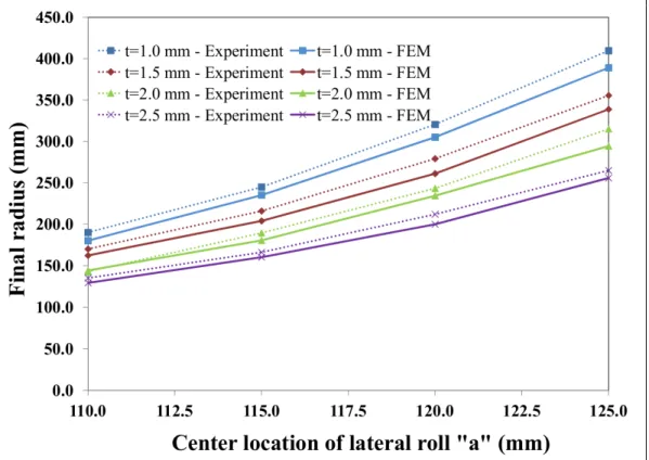
3.6.2 Influence of plate thickness (t) and center location of lateral roll (i.e., a) on final shape radius (R) ... 57
3.6.3 Deformation characteristics of the forming plate ... 58
3.6.4 Influence of plate thickness “t” and center location “a” of lateral roll on bending forces F ... 63
3.6.5 Influence of the plate widths (H) on the bending force ... 66
3.6.6 Influence of the plate thickness (t) on supplied power (W) and rotational speed (RPM) of the rolls ... 67
3.7 Conclusions ...68
3.8 Acknowledgements ...69
3.9 References ...69
CHAPTER 4 ARTICLE #2: HEAT ASSISTED ROLL BENDING PROCESS DYNAMIC SIMULATION...73
4.1 Abstract ...73
4.2 Introduction ...75
4.3 Analytical model ...76
4.3.1 Elastic deformation P1Pe ... 79
4.3.2 Elastic-perfectly plastic deformation PeP2 ... 80
4.3.3 Elasto-plastic deformation P2P3 ... 82
4.4 Computational modeling of heat forming technique ...84
4.5 Finite element model ...86
4.5.1 Element and mesh ... 86
4.5.2 Contact surface and friction model ... 89
4.5.3 Loading ... 89
4.6 Simulations and numerical results ...90
4.7 Conclusion ...99
4.8 Acknowledgements ...99
4.9 References ...99
4.10 Biographies ...102
CHAPTER 5 ARTICLE #3: FE STUDY FOR REDUCING FORMING FORCES AND FLAT END AREAS OF CYLINDRICAL SHAPES OBTAINED BY ROLL BENDING PROCESS ...105
5.1 Abstract ...105
5.2 Introduction ...106
5.3 Asymmetrical roll bending machine and flat areas definition ...110
5.4 Finite element model of the asymmetrical roll bending process ...112
5.5 Experimental study to validate the FE model ...115
5.6 Results and discussion ...120
5.6.2 Moving the bottom roll in the vertical plane ... 124 5.7 Conclusions ...127 5.8 Acknowledgement ...128 5.9 References ...128 CONCLUSION ...131 RECOMMENDATIONS ...135
APPENDIX I: EXPERIMENTS OF HEATING PLATE BY INDUCTION ...137
LIST OF BIBLIOGRAPHICAL REFERENCES ...140
LIST OF TABLES
Page Table 2.1 The features of the three-roll asymmetric and pyramidal model ...19 Table 3.1 FE model and material properties parameters ...43
LIST OF FIGURES
Page
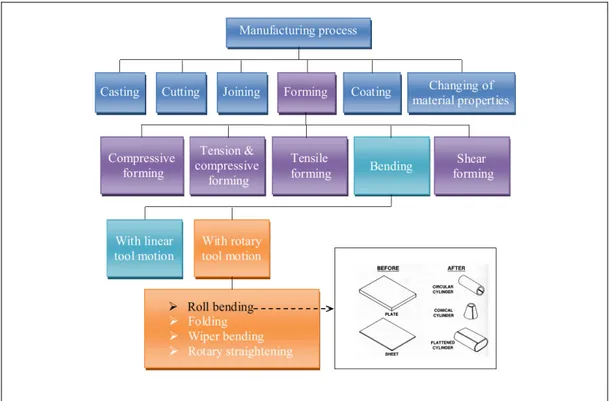
Figure 1.1 The roll bending process in the manufacturing process classification ...3
Figure 1.2 The roll bending process capability (Semiatin, 2006) ...4
Figure 1.3 Examples of roll bending process’s products (Iseltek Co., 2010) ...5
Figure 1.4 Products made by roll bending process (Haeusler, 2010) ...6
Figure 1.5 Example of Francis turbine runners (Alstom, 2014) ...7
Figure 1.6 Scope of research diagram ...8
Figure 2.1 The steam-powered roll bending machine (Allen, 1985) ...14
Figure 2.2 Example of patent relating to roll bending machine (Patented-US807352A, 1905) ...15
Figure 2.3 Three-roll asymmetric configuration ...16
Figure 2.4 Three-roll pyramidal configuration...17
Figure 2.5 Four-roll configuration...18
Figure 2.6 Location of load-cells of four-roll model bending machine (Hua et al., 1999) ...26
Figure 2.7 Location of load-cells of three-roll model (Chudasama and Raval, 2012) ...27
Figure 2.8 Effect of temperature on forming force (Juneja, 2013) ...28
Figure 2.9 Temperature for different metal forming conditions (Mukherjee, 2013)...29
Figure 2.10 Example of conventional line heating work (Yoshihiko et al., 2011) ...30
Figure 2.11 Induction heating system (Larsson, 2005) ...31
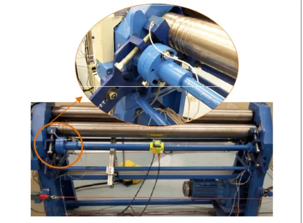
Figure 3.1 Asymmetrical three-roll bending machine ...40
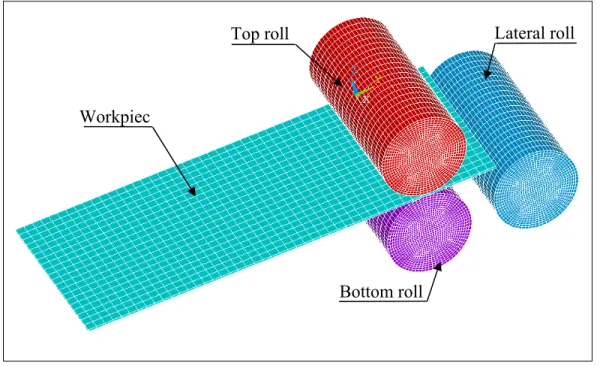
Figure 3.2 FE simulation model of asymmetrical three-roll bending machine ...42
Figure 3.4 Final shape radius verification ...45
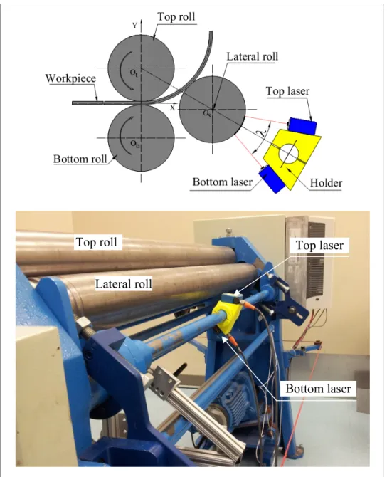
Figure 3.5 Recording deflection of the lateral roll with laser sensors ...46
Figure 3.6 Diagram of deflection checking by laser system ...47
Figure 3.7 Measuring the bending force of the lateral roll ...50
Figure 3.8 Measurement of the top roll deflection ...51
Figure 3.9 Free body diagram of deflection ...52
Figure 3.10 Strain gauges fixed onto workpieces ...53
Figure 3.11 FE simulations of roll bending process at beginning of the process ...54
Figure 3.12 FE simulations of roll bending process at a) midpoint of the process and b) completion of the process ...55
Figure 3.13 Geometric verification model ...56
Figure 3.14 Final radius depending on the plate thickness and the lateral roll center location ...57
Figure 3.15 Strain gauges setup for rolling ...59
Figure 3.16 Strain variation at locations of strain gauges J1, J2 and J3 a) experiments; b) typical location of A, B and C ...60
Figure 3.17 Strain variations depending on center location “a” of the lateral roll ...61
Figure 3.18 Strain variations depending on the plate thickness ...62
Figure 3.19 Top roll bending force based on the plate thickness and center location of the lateral roll ...64
Figure 3.20 Lateral roll bending force depending on the plate thickness and center location of the lateral roll ...65
Figure 3.21 Top roll bending force depending on the plate width ...66
Figure 3.22 Lateral roll bending force depending on the plate width ...67
Figure 3.23 Supplied power depending on plate thickness ...68
Figure 4.1 Asymmetrical three-roll bending machine geometry setup ...77
Figure 4.3 Equilibrium of forces of deformation ...79
Figure 4.4 Heating approach a) at the early stage of heating up; b) during the forming process ...85
Figure 4.5 FE simulation model of heating assisted roll bending process ...86
Figure 4.6 Material properties: thermal expansion coefficient [24] ...87
Figure 4.7 Material properties: a) Young's modulus and b) Yield stress [24] ...88
Figure 4.8 Temperature distributions at 1 sec ...90
Figure 4.9 Temperature distributions at: a) 30 sec and b) the process is completed ...91
Figure 4.10 Temperature distributions at various heat flux values and plate thickness ...92
Figure 4.11 Applied force as a function of heat input: t = 0.001 m and 0.002 m ...93
Figure 4.12 Applied force as a function of heat input: t = 0.004 m and 0.008 m ...94
Figure 4.13 Applied force for plate thicknesses at room temperature ...95
Figure 4.14 Stress distribution at 1 sec...95
Figure 4.15 Stress distribution at: b) 30 sec and c) the process is completed ...96
Figure 4.16 Geometric verification procedure ...97
Figure 4.17 Radius of final shape on the different of heating temperature ...98
Figure 5.1 Flat areas left by a roll bending process ...107
Figure 5.2 Varying the location of the bottom roll a) offset di, and b) the “gap” value gi ...109
Figure 5.3 Parameter of three-roll asymmetric roll bending machine ...110
Figure 5.4 Flat-end definition ...112
Figure 5.5 FE model of the asymmetrical roll bending process ...113
Figure 5.6 Stress-strain curve of plate material ...114
Figure 5.8 Final shape obtained by the FEM ...116 Figure 5.9 Flat end and radius computational procedure ...117 Figure 5.10 Flat end length computational procedure ...119 Figure 5.11 Final radius versus plate thickness and location of the lateral roll ...120 Figure 5.12 Forming force on the rolls versus the values of di ...121 Figure 5.13 Free body diagram of the roll bending process ...122 Figure 5.14 Flat-end length at the leading-end versus the value of di ...123 Figure 5.15 Plate configuration when the bottom moves horizontally ...124 Figure 5.16 Forming force of the rolls versus the value of gi ...125 Figure 5.17 Flat end versus the value of gi. ...126 Figure 5.18 Varying plate contact lines with rolls when moving the
LIST OF ABREVIATIONS a Center location of lateral roll along action line E Young’s modulus of plate material
I Moment of inertia of plate
k1, k2, k3 Curvature of plate at region P1Pe, PeP2 and P2P3 ke The maximum elastic curvature
Kp The stiffness coefficient of system at P1 M1, M2, M3 Bending moment of plate at P1, P2 and P3 Me The maximum elastic moment
Pt, Pb Coordinates of the top and the bottom laser dots on the deformed lateral roll Pt0, Pb0 Initial coordinates of the top and the bottom laser dots on the lateral roll q1, q2, q3 Contact forces at their respective angle θ1, θ2 and θ3
Q1, Q2, Q3 The applied forces by the respective top, bottom and lateral roll R Radius of the rolled cylinder
r Radius of the rolls
s1, s2, s3 Arc length coordinate of P1Pe, PeP2 and P2P3
s Initial arc length made by two laser beams dotting in lateral roll
t Plate thickness
xos, yos Initial location of the lateral roll center xod, yod Location of the lateral roll center under force Y the yield stress of plate
λ Angle between the two laser beams θ1, θ2, θ3 Inclined angle of plate at P1, P2 and P3 θ Operating action line angle of offset cylinder δ The deflection of the roll at contact point P1 ν Poisson’s ratio of the material
υ Deflection of the top roll
υlr Deflection of the lateral
INTRODUCTION
The high strength steel axisymmetric hollow shapes are widely used in many fields of industry dealing with heavy cyclic loads and corrosive environments. But processing this type of steel is not easy, and it becomes a hard-to-solve problem when the part to produce is large and quasi-unique. Examples of high strength steel axisymmetric hollow parts are the crown of a Francis turbine runner or the tower of a wind turbine. Several processes can be envisaged for the manufacturing processes of such large parts (welding or casting…), but few processes can deliver one within a reasonable time and at competitive cost. Among them the roll bending is considered as an interesting alternative method.
Roll bending process is the plastic deformation of a metal that uses a set of rolls to bend a flat plate into various shapes such as cylinders, cones or ovals. It is a continuous three-point bending process with negligible change in plate thickness. Many different types of roll bending machines have been developed over the past few decades to adapt to various forming production specifications. However, the three-roll asymmetric model produces more accurate final shape, capable of forming a wider range of plate thicknesses, and especially, this kind of machine can be loaded and unloaded much faster than a three-roll pyramidal model. According to a literature review, most theoretical models, FE simulations and experimental verifications focused on four-roll model or three-roll pyramidal model but rarely on three-roll asymmetrical configuration.
After Chapter 1, general information about the roll bending process, and Chapter 2, which presents literature review, the thesis continues with Chapter 3 where a 3D dynamic finite element to simulate the forming process of the asymmetrical roll bending machine is compared to experiments. Parameters that affect the accuracy of the final shape, the bending forces and the residual strain left in the formed plate are investigated. In Chapter 4, the second step of this research is to find the strategies for reducing forming forces and improving final part quality. Two techniques are proposed to reduce forming forces: heating plate and optimize the setup for the rolls position. Heat assisted metal forming will be
unavoidable if the forming forces necessary to bend the plate in cold working conditions exceed the capacity of the machine. The relationships between the heating plate temperature and the output parameters of roll bending process such as applied forces and final shape quality have been studied by performing FE simulation and analytical computations. These results yield to a better understanding of the mechanism of the process and provide an opportunity for the design of an efficient heating system to control the heat energy to be input in the plate during the roll bending process. Chapter 5 proposes one more method to reduce forming forces and to improve the accuracy of the cylindrical shapes obtained by the roll bending process. This approach includes moving the bottom roll slightly along the feeding direction and adjusting the bottom roll location. Sensitivity analyses were performed using a developed 3-D dynamic finite element model of an asymmetrical roll bending process in the Ansys/LS-Dyna software package. Simulations were validated by experiments run on an instrumented roll bending machine. The FE results indicate that this new approach not only minimizes the flat end areas but also reduces the forming forces.
Since large-casting possibilities have disappeared from Canada’s industry, this research is a real opportunity for finding interesting alternatives to manufacture large and hollow axisymmetric parts.
CHAPTER 1
GENERAL INFORMATION AND THESIS ORGANIZATION
This chapter gives first an overview of the roll bending process and secondly scope and structure of the thesis.
1.1 Overview of the roll bending process
Roll bending is a continuous forming process that uses a set of rolls to bend a flat plate into various shapes such as cylinders, cones or ovals. As categorized by German standard DIN- 8580 in Figure 1.1, this is a subgroup of forming process which is the plastic deformation of a metal around a linear axis with little or no change in surface area and thickness (Schuler, 1998).
Like other forming processes, roll bending can be used to form any plate or sheet having enough ductile properties to be cold formed. It includes mild steels, stainless steels and heat resistant alloys (Todd et al., 1994). Furthermore, nonferrous light alloys such as aluminum and copper alloys can also be successfully formed by this forming process. In practice, the minimum radius of the parts produced by roll bending process are typically limited by diameter of the rolls and type of machines, while the size and power of machine are the principal factors limiting the plate thickness and the width of final shape. As shown in Figure 1.2, the process capable can range from 150 mm (6.0 inch) to 5000 mm (200 inch) in final shape diameter with the plate thickness of approximately from 0.5 mm (0.02 inch) to 254 mm (10 inch) (Todd et al., 1994). Today, the products of the roll bending process can be larger, wider and very much thicker. In a few applications, final shape with 300 mm in plate thickness or 12000 mm in width can be successfully formed by roll bending process (Semiatin, 2006).
Figure 1.2 The roll bending process capability (Semiatin, 2006)
In comparison with other cold forming processes, such as deep drawing or contour roll forming, roll bending process has some unique advantages: wide range of final shape dimension, large plate thickness, numerous material applicability, process flexibility and good surface finish. Therefore, although it is an old process having a long history over of century, roll bending process is still the most practical method of producing large cylinders
and axisymmetric hollow shapes. Figure 1.3 illustrates some example parts could be produced by roll bending process.
Figure 1.3 Examples of roll bending process’s products (Iseltek Co., 2010)
This kind of forming process can be also used for manufacturing a wide range of products for various industries (see Figure 1.4) such as, asymmetrical cones (wind tower), silo construction or semi-finished products.
Wind tower Semi-finished products Silo-construction
Figure 1.4 Products made by roll bending process (Haeusler, 2010)
Moreover, this process is beginning to be taken into serious consideration by industries for producing large, thick parts such as the thick, conically shaped of wind tower (Seravesi, 2006) or the crown (see Figure 1.5) of Francis turbine runner (Seravesi, 2006; Zeng, 2007). Some Francis turbine runners installed in the dam basement of a hydraulic power plant are 10 meters in diameter with more than 5 meters in height, while plate thickness can exceed 100 millimeters (Zeng, 2007). Several processes can be envisaged for the manufacturing processes of such large parts (welding or casting…), but few processes can deliver one within a reasonable time and at competitive cost. Among them the roll bending process, causing plastic deformation of a plate around a linear axis with little or no change in plate thickness, is considered as an interesting alternative.
Figure 1.5 Example of Francis turbine runners (Alstom, 2014)
1.2 Scope of research
One goal of this research is to find the forces needed to shape axisymmetric hollow parts and thus to provide the methods for reducing the forming forces. Another goal is to predict the final shape geometry and quality. Currently, the finite element method is one of the most powerful numerical tools for achieving these goals. The diagram in Figure 1.6 indicates the relationship between input and output parameters of the roll bending process that have been investigated via this thesis.
Band of a Francis turbine
Figure 1.6 Scope of research diagram
Throughout this research, contributions have been made in five areas on the roll bending process.
1.2.1 Study the effects of the roll bending process parameters
This model investigates the parameters that affect the accuracy of the final shape, the forming forces and the residual strains left in the formed plate. The relationships between temperature, forming forces and plate thickness have also been investigated. A setup for the rolls was proposed in order to reduce forming forces and the flat areas at leading and trailing edges.
1.2.2 Develop 3D dynamic FE model of the roll bending process
A 3D dynamic FE model was developed in the Ansys/LS-Dyna environment and was validated satisfactorily through experiments. In an industrial context, the radius of the final shape in the roll bending process is generally determined based on “trial-and-error” or an
empirical approach, which requires several attempts. Therefore, applying this FE model in manufacturing plants will be beneficial in providing the accuracy of the final shape’s radius. This FE model also provides a better understanding of forming force for selecting or designing a machine capacity based on the plate thickness and the final shape sizes. Additionally, using this FE model will considerably reduce the setup time before manufacturing and increase the effectiveness of an existing asymmetrical roll bending machine.
1.2.3 Perform roll bending process experiments
A three-roll asymmetric bending machine was used to validate the FE models. To ensure qualitative experimental results, different measuring devices were used to verify the same output quantities of forming forces in this research such as indicators, load-cells and laser sensors. The final shape radii were evaluated by EXAscan laser scanner. The rotational speed of the rolls, supplied power, friction coefficient between the plate and rolls was checked by suitable equipments. In addition, a new experimental approach for measuring strains with strain gauges to obtain the strain variation left in the formed plate is also proposed in this research.
1.2.4 Analysis theory of roll bending process
By equilibrium of forces for each zone of bending plate, the theoretical study was developed in this research to study the forming forces depending on the various forming parameters.
1.2.5 Live strain gauge measurements
The analysis and measurement of the residual strain left in a roll bent plate are usually difficult to obtain, and no rigorous study on measuring strains during roll bending has been reported in literature to our knowledge. In this study, the strain gauges were mounted on the specimen surface and passed the rolls through grooves at the bottom and lateral rolls during
the bending process to record the strain variations. FE results and experiments were compared and analysed for a better understanding of the deformation behavior of the workpiece before and after passing the bending roll. It also provides an accurate residual strain measurement procedure that relates the workpiece properties to the final shape dimensions and process parameters.
1.3 Outline of thesis
This thesis is divided in five chapters. It starts with chapter one about general information and chapter two on literature review. The three following chapters, presented as three journal articles, expose the main results of the research. Finally, conclusions, recommendations and suggestions for future work are also outlined. The detailed content is as follows:
Chapter 2, literature review, gives a comprehensive review related to roll bending process of the published literature to gain a better understanding the scope of thesis. It starts with a review of classification, advantage and disadvantage and the state of art of the roll bending process. In the second section, three main investigation techniques usually used in the research of the roll bending process are discussed. It includes analytical study, experimental investigation and finite element analysis. Detailed reviews on heat assisted and finite element theory on sheet metal forming are also presented in the final section of this chapter
Chapter 3, journal article No. 01 - “Analysis of the asymmetrical roll bending process through dynamic FE simulations and experimental study”, explains in details the techniques used to analyse the asymmetrical roll bending process through dynamic FE simulations and experimental study. This chapter then investigates the parameters that affect the accuracy of the final shape, the bending forces and the residual strains left in the formed plate. The FE simulation results are compared with experiments performed on an instrumented roll bending machine and are in good agreement.
Heat assisted roll bending process dynamic simulation is presented in Chapter 4, journal article No. 02 – “Heat assisted roll bending process dynamic simulation”. In this paper, a computer aided simulation program has been built in the Ansys/LS-Dyna environment to study the relationships between temperature, applied forces and plate thickness. The finite element modelling of the formed geometry is sequential with first a thermal simulation followed by a structural one. The numerical results are then compared to analytical ones. The analyses of the process with numerical simulations yield to a better understanding of the mechanism of the process and provide an opportunity for the design of an efficient heating system to control the heat energy to be input in the workpiece during the roll bending process.
Chapter 5, journal article No. 03 – “FE study for reducing forming forces and flat end areas of cylindrical shapes obtained by roll bending process”, proposes one more method to reduce forming forces and to improve the accuracy of the cylindrical shapes obtained by the roll bending process. This approach includes moving the bottom roll slightly along the feeding direction and adjusting the bottom roll location. Sensitivity analyses were performed using a developed 3-D dynamic finite element model of an asymmetrical roll bending process in the Ansys/LS-Dyna software package. Simulations were validated by experiments run on an instrumented roll bending machine. The FE results indicate that this new approach not only minimizes the flat areas but also reduces the forming forces.
The thesis will be concluded in final section. It summarises key conclusions of this research about the parameters that may affect the output of the roll bending process, the method to reduce the forming forces and improve the final shape quality. Recommendations and suggestions for future work are also proposed in this section.
CHAPTER 2
LITERATURE REVIEW
This chapter presents a literature review of published studies on the roll bending process to enhance understanding of the thesis objective. As mentioned, this research deals with finding the forming forces and predicting the final shape geometry via experiments and FE simulations. The literature review is divided in four sections, as follow:
1 The roll bending process - state of the art: history, classification, operation, advantage and disadvantage.
2 Investigation techniques for studying the roll bending process: • Analytical approach;
• Experimental approach;
• Finite element analysis approach. 3 Heat assisted sheet metal forming. 4 Summary.
2.1 The roll bending process - state of the art
It is not known when the first roll bending machine was introduced in the industry (Jenkins, 1936) but a similar machine was already operated in 1828. A few years later - in 1840, Sir William Fairbairn, a shipbuilder, built plate bending rolls to make boilers and other products made of iron and steel plates. During the Industrial revolution, steam engine was used to power the roll bending machine. Figure 2.1 shows a steam-powered plate bending rolls found at Sheepford Boiler Works, Scotland (Allen, 1985).
Figure 2.1 The steam-powered roll bending machine (Allen, 1985)
Between the late 19th and mid-20th centuries, the core technology of the roll bending machines was handheld. Various patents relating to such machines were found in these times with Figure 2.2 showing an example. Individual electric motors replaced progressively steam engine as power source.
Since the 1950's, servomechanisms and then hydraulic motors were applied to control the paths of the roll bending machine. The products of the roll bending machine are thus more accurate.
Figure 2.2 Example of patent relating to roll bending machine (Patented-US807352A, 1905)
Nowadays, many different types of roll bending machines have been developed over the past few decades to adapt to various forming production specifications. However, these roll bending machines can be classified into two major types in the currently market: a three-roll model (including pyramidal and asymmetrical models) and a four-roll model (Hua and Lin, 1999). Roll bending process operations can be described as follows:
Three-roll asymmetric configuration (shown in Figure 2.3)
The manufacturing steps are described below (Semiatin, 2006) and (Faccin, 2014):
Feed the plate into machine and move up the roll No.1 to “pinch” the plate. Rotate the roll No.1 and No.2 to pre-bent the plate.
Reverse the roll No.1 and No.2 to remove the plate.
Enter the plate into the machine from the other end and adjust the roll No.3 to final position.
Complete cylinder and move down the roll No.1 to remove the final part.
Figure 2.3 Three-roll asymmetric configuration
2
1
Three-roll pyramidal configuration (shown in Figure 2.4)
The manufacturing steps are described below (Semiatin, 2006), (Zeng, 2007) (Schleifstein, 2014) and (Faccin, 2014) :
Feed the plate into machine and move down the roll No.2 to a defined position. Rotate the roll No.1 and No.3 to rough forming the plate.
Edge bending 1 at the leading edge of the final part.
Reverse the roll No.1 and No.3 to edge bending 2 at the trailing edge of final part. Complete cylinder and move up the roll No.2 to remove the final part.
Figure 2.4 Three-roll pyramidal configuration
2
Four-roll configuration (shown in Figure 2.5)
The manufacturing steps are described below (Zeng, 2007), (Roundo, 2012; Schleifstein, 2014) and (Faccin, 2014):
Place the plate to machine and move up the roll No.1 to “pinch” the plate. Move up the roll No 3-b and rotate the roll No.1 and No.2 to form the plate.
Swap the roll No.3-a up and move down the roll No.3-b to continue form the plate. Complete cylinder and move down the roll No.1 and No.3-a to remove the final part.
Figure 2.5 Four-roll configuration
3-a
3-b
1
Selection between a three-roll model and four-roll model machines depends mainly on the accuracy requirements, the dimension of products to achieve, the shape of the parts to be produced and the cost of machine (Marshall, 2010). The biggest advantage of four-roll model that have over the other three-roll machines is simplicity and easy cone bending (Hua and Lin, 1999) and (Zeng, 2007). But one advantage of three-roll model is its cost in current market. Three-roll model typically cost less than comparable four-roll model machines (Marshall, 2010). In this thesis, three-roll asymmetric model is selected to study forming forces and bending quality. Since there are two types of three-roll bending machines, let’s briefly review the features of both. Table 2.1 compares main characteristics of three-roll bending machines.
Three-roll asymmetric configuration Three-roll pyramidal configuration Capable to pre-bend, leaves a smaller flat area
at the leading and trailing ends in comparison to a three-roll pyramidal machine.
Unable to pre-bend, leave larger flat areas at both leading and trailing ends of the final shape.
Capable of forming a wider range of plate thickness than a three-roll pyramidal machine because of the method of feeding.
Definite limitations on the minimum thickness of the plate that can be rolled because the top roll is an idler Unsuitable for forming the workpieces from
angles, channels, and other structural shape.
Permissive for forming irregular shapes of the plate that is not adaptable to three-roll asymmetric model.
More accurate final shapes and it can be loaded and unloaded much faster than the three-roll pyramidal machine.
Less force demanded for a given deflection because forming forces are almost applied midway between the two bottom rolls.
The three-roll asymmetric model produces more accurate final shape, capable of forming a wider range of plate thicknesses, and especially, this kind of machine can be loaded and unloaded much faster than a three-roll pyramidal model.
The objective of this thesis is to study the feasibility of three-roll asymmetric model in forming axisymmetric hollow shapes for reducing forming forces and improving final part quality by employing numerical and experimental methods
2.2 Investigation techniques for studying the roll bending process
2.2.1 Analytical approach
2.2.1.1 Relationship between the curvature and displacement of the forming roll
Roll bending process seems to be a rather simple process, but the curvature of the bent plate is not that easy to handle by a theoretical analysis (Hansen and Jannerup, 1979). Since 1970s researchers focused on analysis of deformation of the plates in order to produce parts with better accuracy, (Hansen and Jannerup, 1979) proposed a function based on simple theory of plastic bending to find the position of top roller corresponding to a desired curvature for the final shape. (Hardt et al., 1982) developed a shape control for a three-roll pyramidal model. This closed-loop control was designed to determine the relationship between bending moment and curvature and to compensate the springback of the workpiece in real time. In a research by (Seddeik and Kennedy, 1987), theoretical analyses lead to the minimization of total potential energy with a Rayleigh-Ritz technique. This analytical approach is used to calculate the relationship between the radius of curvature of bent plate and the resulting distortion in the cross section. (Yang and Shima, 1988) simulated deformation of the plate with a U-shaped cross section bent in a pyramid type three-roll bending machine. In this study, based on the properties of the plate, the authors calculated the bending moment and the curvature distribution of the plate in accordance with the displacement of the center roll and the rotation of the side rolls. Via elementary method, (Yang et al., 1990) also analysed
the relationship between the bending moment and the curvature distribution of the plate. These results were then used to build an automatic control system for producing a U-shaped cross section bent bar with a pyramid type three-roll bending machine. The analysis of the motion of rolls for forming a plate into a desired curvature in a pyramid type three-roll bending machine has been carried out by (Yang et al., 1994). In this research, the authors used FEM simulation and fuzzy reasoning to determine the path of the forming roll. In each deformation step of FEM simulation, the movement of forming rolls is iteratively adjusted by a feedback control based on fuzzy reasoning. Others have concentrated on relationship between the curvature and displacement of the forming roll. By assuming the contact point to be shifting at the bottom roll plate interfaces and neglecting the changing of material properties during deformation and the effecting of initial strain, (Gandhi and Raval, 2008) proposed an analytical to estimate the position of the top roll as a function of final radius of curvature for a pyramid type three-roll plate bending machine.
2.2.1.2 Forming process principle
Most of the published literature along history focused on working principle and relevant deformation mechanisms see for example the work of Hua et al. However, all of these theory models were developed for four-roll model but not for three-roll asymmetric model.
By separating the bending process into 1) the edge preparation bending mode and 2) the continuous bending mode, (Hua et al., 1994) discussed relevant mechanism and its influential parameters for the continuous four-roll model. (Hua et al., 1995) developed a mathematical model to determine the internal bending resistance at the top rolls contact for multiple pass process on a four-roll bending model. In 1997, (Hua et al., 1997) proposed a formulation by equilibrium of the internal and external bending moment about the top roll contact to determine the bending force on the rolls in the continuous single pass four-roll model. Some mathematical models have been also established by (Hua and Lin, 1999) to simulate the forming of elastic-perfectly plastic plates on a continuous four-roll model bending machine.
(Hua et al., 1999) analyzed the working principles and some relevant bending mechanics of the rolls to exploit more fully the potential of the benders for manufacturing large and medium sized tubular sections on four-roll model.
(Hua and Lin, 1999) provided an analytic approach to study the effect of an arbitrary strain hardening plate in edge bending mode with the four-roll model. The mathematical model is developed by solving the governing differential equation for the large deflection of an elasto-plastic thin plate having general strain-hardening law. Influence of material strain hardening on the mechanics relevant to the whole process of four-roll bending machine was then investigated via this mathematical model. Based on the same analysis technique of (Hua and Lin, 1999), in a more recent study, (Lin and Hua, 2000) analyzed influence of material strain hardening on the mechanics relevant to the continuous mode on the four-roll model bending machine. Deformation of plate for edge bending mode on four-roll model bending machine was discussed via mathematical model by (Lin and Hua, 1999). The parameters relevant to this forming process were also defined in this research. (Hu and Wang, 2001) applied upper bound and lower bound methods to study the mechanism of the roll bending process. In their paper, a new roll bending model was proposed. This model resolves a few inadequacies of traditional roll bending processes and allows more flexibility in the formation of large bending parts.
2.2.1.3 Reaction force
The reaction forces during bending process are dependent on several parameters: plate thickness, plate width, material properties and diameter of final shape to be bent. With consuming most of the machine power, the maximum bending force is one of the most important information for designing bending equipment. Analytical models developed in the literature addressed the problem of bending force prediction for three-roll pyramidal model. (Gajjar et al., 2007) developed analytical models for equivalent thickness and equivalent width, which are based on the power law material model for studying the bendability within the machine capacity. By equating the external bending moment to internal bending moment
developed in the plate, (Chudasama and Raval, 2012) proposed an analytical model for the prediction of bending force during the multiple pass 3-roller conical bending. A similar approach has also been employed by (Chudasama and Raval, 2013) to present mathematical model for force prediction for 3-roller conical bending process. Effects of various material properties and geometrical parameters on the bending forces have been studied in detail. (Chudasama and Raval, 2014) developed the numerical model for the prediction of the bending force during dynamic stage of 3-roller conical bending process. In considering shear stresses developed in the plate along with the normal stresses during the roll bending, this analyis can be effectively used to get the roller bending force as well as the effects of various parameters like material parameters and geometrical parameters on it.
2.2.1.4 Accuracy of the final shape
Most of the analytical models developed in previous studies focus on forming process principle, reaction forces and relationship between the curvature and displacement of the forming roll. But few references are addressing the problem of the flat ends extents and the accuracy of the final shape.
The mechanics of the three-roll bending process for smoothly curved plates has been proposed by (Shin et al., 2001). Both analytical and finite element approaches were applied to develop a logical and accurate procedure for determining the center roller displacement required for the fabrication of a plate with the desired curvature. The analytical approach has been obtained by modifying and extending an existing model based on the beam theory. The finite element models built for comparison purposes, one with beam elements and the other one with plane strain shell elements, show that the analytical approach yields to sufficiently accurate results for smoothly curved plates and may be used to determine the center roller displacement according to the desired curvature. In order to improve the quality and productivity of final shape that is produced by roll bending process, (Gandhi et al., 2009) develop the formulation of springback and machine setting parameters for continuous multi-pass bending of conical shape on three-roll bending machines. In this paper, effect of change
of flexural modulus during the deformation was incorporated to study the effect on spring-back prediction. (Cai and Lan, 2011) analyzed the straight end problem in a thin plate, pyramid-type machine through the development of an analytical method. However, the authors did not discuss the flat areas produced by a three-roll asymmetric machine and did not propose a method to reduce the straight end.
2.2.2 Finite element analysis approach
Through the last decades it has been discovered that it is expensive and time consuming to run experimental investigations that may only give a limited understanding of the roll bending process. Moreover, the interest in simulating and accurately predicting the deformations during the roll bending process and the geometrical characteristics on the final product has been increased. Therefore, the application of numerical simulation of the roll bending process was suggested.
According to (Logan, 2006), “The Finite Element Method (FEM) is a numerical method for solving problems of engineering and mathematical physics” The term FEM was coined by Ray W. Clough in his publish in 1960 (Logan, 2006). The first commercial finite element analysis code came of age in the early 1960’s with the replacement of analogue with digital computers. At this early stage, the application was confined to static analysis to evaluate the performance of the machine structure. For studying about roll bending machine stands, (Ramamurti et al., 1992) performed FE simulation to study the static response of the frame of a three-roll pyramidal machine when it is in operation.
Roll bending process modeling is a high nonlinear problem and required intensive and costly computational operations. With the continuous development of computers, memory requirements and computer performance are extremely improved in recent years. The limited nonlinear solvers such as, nonlinear behaviors of material, nonlinearity due to contact or nonlinear loading, were developed and made available in commercial FEM software, such as ANYSY/LS-DYNA, ABAQUS, AUTOFORM, etc. Instead of using an implicit analysis, 3D
explicit FE analysis method has been chosen by most researchers to analyse and simulate such kind of nonlinear behaviour exhibited by the roll bending process. (Zeng et al., 2008) developed 3-D simulations based on the elastic-plastic explicit finite element method with Ansys/LS-Dyna to study the dynamic process of the three-roll pyramidal model. In this study, the kinematic relationship existing between rolls and workpieces, the geometrical setup and the finite element mode are discussed in detail for manufacturing a conical tube using the conical rolls of a three-roll pyramidal model. Feng et al conducted a considerable amount of FE modeling and simulation to investigate the three-roll bending process. In 2009, (Feng et al., 2009) developed a finite element model for studying non-kinematical pyramidal three-roll bending. By using the attachments to reduce the velocity on the area close to the top edge of the plate, this FE model can be used to simulate the manufacturing of the conical parts with cylindrical rolls on a pyramidal three-roll bending machine. Based on the same approach, (Feng and Champliaud, 2012) developed a FE model of pyramidal three-roll bending process to produce the conical shapes with conical rolls. In 2011, (Feng and Champliaud, 2011) proposed a three-stage process to improve the geometrical quality of a bent cylinder obtained from FE simulations. The asymmetrical three-roll bending process was also developed by (Feng and Champliaud, 2011) in 2011. This FE models were capable of predicting the position of the lateral roll and helped to increase the productivity by improving the traditional trial and error technique. (Ktari et al., 2012) and (Fu et al., 2013) also used the commercial finite element package, ABAQUS/Explicit environment, to study the forming process of the pyramidal three-roll bending.
2.2.3 Experimental approach
FE simulations or theoretical analyses may have the potential to provide a better understanding of the phenomena in the roll bending process, and can therefore decrease the setup time before manufacturing and the amount of materials wasted by using the trial-and-error approach. However, before applying these techniques to the actual process, verification via experiments are used to validate the numerical model. Most of the experimental published works that addressed the relationship between the curvature and displacement of
the forming roll were used to validate the theoretical approach. It includes the publications of (Hansen and Jannerup, 1979), (Hardt et al., 1982), (Seddeik and Kennedy, 1987), (Yang and Shima, 1988), (Yang et al., 1990), (Yang et al., 1994) and (Gandhi and Raval, 2008). Different experiments have been conducted to study: a) the forming process principle (Hu and Wang, 2001) and (Ramamurti et al., 1992); b) the FE simulations (Feng and Champliaud, 2011) and (Fu et al., 2013). Experimental investigations of forming forces have been carried out by some researches. (Hua et al., 1999) used the load-cells to measure the forming force acting on the rolls of four model roll bending machine as shown in Figure 2.6.
Figure 2.6 Location of load-cells of four-roll model bending machine (Hua et al., 1999)
Each load-cell can measure the axial force and bending force and the recorded signal was converted to a resultant force. Using the same measurement approach, (Chudasama and Raval, 2012) attached the load-cells to the rolls of a three-roll pyramidal model to measure the reaction force at the top and at the bottom roll as shown in Figure 2.7
Figure 2.7 Location of load-cells of three-roll model (Chudasama and Raval, 2012)
2.3 Heat assisted metal forming
In metal forming industries, processes may be carried out for three basic working temperature ranges: cold, warm and hot (Mukherjee, 2013). The review of manufacturers’ practices indicated that most the metal forming process is generally performed at room temperature because it offers a number of distinct advantages at this working condition. However, heat assisted metal forming will be unavoidable if the forming forces necessary to bend the plate in cold working conditions exceeded the capacity of the machine.
As shown in Figure 2.8, most of the metallic materials become softer at high temperatures. Strategic use of heat input could help to lower forces required for forming.
Figure 2.8 Effect of temperature on forming force (Juneja, 2013)
Lower accuracy and surface finish, higher production cost and shorter tool life are basically drawbacks of the hot forming. But in comparison with cold and warm forming, hot forming has some advantages such as, lowering forces and power required, increasing the amount of deformation and reducing strain hardening (Mukherjee, 2013) and (Juneja, 2013). Therefore, at higher temperature any deformation operation can be performed with lower forces and less power. It leads to reduce the cost of equipment needed for the process.
As shown in Figure 2.9, where TA is the room temperature and Tm is the melting temperature of the material, the boundary between warm and hot conditions is defined by temperature of re-crystallization. Cold working is metal forming at room temperature, warm forming is performed at a temperature higher than room temperature but lower than the crystallization temperature while hot working is carried out at temperatures above the re-crystallization temperature (Mukherjee, 2013).
Figure 2.9 Temperature for different metal forming conditions (Mukherjee, 2013)
The metal forming process in hot condition is basically done using one of these two options: globally heated plate or locally heated plate (Larsson, 2005). Globally heated plate is heat assisted metal forming where the entire of the bent plate is heated uniformly to one target temperature in an oven. The heated plate is then fed into the machine for forming. Another method used for softening the material in hot forming is known as locally heating or line heating. This forming technique has been an active research topic in manufacturing, especially in ship-building (Yu et al., 2001). A simple example of conventional line heating work can see in Figure 2.10.
Globally heated plate can be formed more easily than when it is locally heated, but the plate has to be removed from the oven to the machine itself with heat loss occurring during the transfer (Larsson, 2005). Maintaining the temperature at an acceptable working limit in the plate thus is a great challenge for this heat assisted forming process.
Figure 2.10 Example of conventional line heating work (Yoshihiko et al., 2011)
The literature review illustrate that most of the researchers in previous studies focused on thermal forming, known as tool less or non contact material forming technology of sheet metals. There are limited studies available in heat assisted process in metal forming. For thermal forming, gas (oxy-fuel) flame, laser, plasma and inductor are mainly heat sources using for sheet metal bending (Tangirala, 2006), (Liu et al., 2009). With the earliest work on laser forming beginning in the mid-1980s (Yu et al., 2001), many of the process and material parameters were analyzed using laser heat sources both experimentally and analytically. In comparison with plasma, laser provides a highly controllable heat source. The plate surface therefore could be rapidly heated by this heat source (Tangirala, 2006). An alternative to lasers to provide a cheaper and safer means to bend plate (Tangirala, 2006), plasma jet forming used a non transferred plasma arc as a heat source to create the necessary thermal gradient in the plate. Compared to other heat sources, induction heating has good controllability, repeatability and a pollution-free working environment (Larsson, 2005). It is
therefore a promising technology that will be used in a wide range of industries for metal forming application. This system mainly consists of an induction coil, an electrically conductive part and switched power electronics as shown in Figure 2.11 (Larsson, 2005). According to Faraday's Law, an electrically conductive part is located inside or in the nearness of the coil and eddy currents will be induced in the object when alternating voltage is applied. As a result of the Joule effect, eddy currents will produce heat.
Figure 2.11 Induction heating system (Larsson, 2005)
Though heat input of the three heat sources are different, the forming mechanisms are the same (Liu et al., 2009).
2.4 Summary
This chapter presented a literature review of topic regarding the state of the art of the roll bending process, investigation techniques for studying it and heat assisted metal forming.
The roll bending process is a process having a long history over one century; it is still the most practical method of producing large cylinders and axisymmetric hollow shapes. Based on the discussions above, some major knowledge gaps can be drawn:
The three-roll asymmetric model produces more accurate final shape, capable of forming a wider range of plate thicknesses, and especially, this kind of machine can be loaded and unloaded much faster than a three-roll pyramidal model. However, most theoretical models, FE simulations and experiment verifications in the literature focused on four-roll model or three-roll pyramidal model but none of them on three-roll asymmetrical model. The parameters that affect the accuracy of the final shape, the bending forces and the residual strains left in the formed plate is only partially understood. Thus, there are many challenges for understanding the forming process with this type of machine.
The forming forces can be reduced by heating the plate. But, to the author’s knowledge, up to now, there is no published study about heat assisted roll bending process. In this research, the relationships between the heating plate temperature and the output parameters of roll bending process such as applied forces and final shape quality have been studied by performing FE simulation and analytical computations. These results yield to a better understanding of the mechanism of the process and provide an opportunity for the design of an efficient heating system to control the heat energy to be input in the plate during the roll bending process.
A roll bending process that minimizes the flat areas at the leading and trailing ends of formed plates will produce more accurate and easier to butt joint the bent ends of the plate. There are several methods of minimizing flat areas, but these techniques are costly or difficult to apply for thick plates. Via FE simulations in Ansys/LS-Dyna software package, this study proposes a new, simple approach that reduces these flat areas. This approach includes moving the bottom roll slightly along the feeding direction and adjusting the bottom roll location. The FE results indicate that this new approach not only minimizes the flat areas but also reduces the forming forces.
The analysis and measurement of the residual strain left in a roll bent plate are usually difficult to obtain, and no rigorous study on measuring strains during roll bending has been reported, to our knowledge, in the literature. In this study, strain gauges were mounted on the specimen surface and passed through the rolls without been crushed, thanks to the grooves machined in the bottom and lateral rolls. Finite element results and experiments were compared and analysed for a better understanding of the deformation behaviour of the workpiece before and after passing the bending roll.
CHAPTER 3
ARTICLE #1: ANALYSIS OF THE ASYMMETRICAL ROLL BENDING PROCESS THROUGH DYNAMIC FE SIMULATIONS AND EXPERIMENTAL STUDY
Quan Hoang Tran • Henri Champliaud • Zhengkun Feng • Thien My Dao
Mechanical engineering department, École de technologie supérieure (ÉTS), Montréal (Québec) H3C 1K3, Canada
Article published in International Journal of Advanced Manufacturing Technology, Volume 75, Issues 5, pp. 1233 - 1244, 2014
3.1 Abstract
Because it is influenced by various processing parameters, predicting the bending force and improving the accuracy of the final shape are significant challenges in the roll bending process when the part to be produced is large and made of high-strength steel. In this paper, a 3D dynamic Finite Element (FE) model of an asymmetrical roll bending process is developed using the Ansys/LS-Dyna software. This model investigates the parameters that affect the accuracy of the final shape, the bending forces and the residual strains left in the formed plate. The simulation results are then compared with experiments performed on an instrumented roll bending machine. Strain measurements are also performed during forming with strain gauges fixed onto plate blanks. A good agreement between the experiments and simulations has been obtained.
Keywords Roll bending process • Dynamic FEM simulation • Ansys/LS-Dyna • Forming process
Résumé
La prédiction de la force de formage et l’amélioration de la précision de la forme finale sont des défis importants dans le processus de cintrage lorsque la pièce à réaliser est de grande dimension et faite d’acier à haute résistance. Dans cet article, un modèle 3D dynamique par éléments finis (FE) d'un processus de formage par roulage asymétrique est développé en utilisant le logiciel Ansys/LS-Dyna. Ce modèle examine les paramètres qui influencent la précision de la forme finale, les forces de flexion et les contraintes résiduelles laissées dans la plaque déformée. Les résultats des simulations sont ensuite comparés aux expérimentations réalisées avec une machine de roulage instrumentée. Les mesures de déformation sont également effectuées pendant le formage avec des jauges de contrainte fixées sur la plaque. Une bonne corrélation entre les mesures expérimentales et les simulations a été obtenue.
Mots-clés: Procédé de roulage • Analyse dynamique par éléments finis • Ansys/LS-Dyna • Procédé de formage
Nomenclature
a Center location of lateral roll along action line E Young’s modulus of plate material
I Moment of inertia of plate
Pt, Pb Coordinates of the top and the bottom laser dots on the deformed lateral roll Pt0, Pb0 Initial coordinates of the top and the bottom laser dots on the lateral roll
t Plate thickness
R Radius of the rolled cylinder r Radius of the rolls
s Initial arc length made by two laser beams dotting in lateral roll xos, yos Initial location of the lateral roll center
xod, yod Location of the lateral roll center under force λ Angle between the two laser beams
θ Operating action line angle of offset cylinder ν Poisson’s ratio of the material
υ Deflection of the top roll
υlr Deflection of the lateral
µ Friction coefficient
3.2 Introduction
Roll bending is a continuous forming process that uses forming rolls to bend plates, sheets, and even rolled shapes into the desired shape: cylinders, cones or ovals. Given the advantages, such as reducing the setup time, the raw material, and the tooling and equipment costs, the roll bending process is one of the most used techniques for manufacturing axisymmetrical shapes. Moreover, this process is a manufacturing method that is beginning to draw significant attention by industries for producing large, thick parts, such as the thick conical shape of the crown of a Francis turbine runner or of a wind turbine tower.
Many different types of roll bending machines have been developed over the past few decades to adapt to various forming production specifications. However, these roll bending machines can be classified into two major types currently in the market: a three-roll model and a four-roll model. The three-roll model includes pyramidal and asymmetrical models, for which basic principles and operations can be found in Ref.[1]. Generally, an asymmetrical model produces a more accurate final shape. In addition, it can be loaded and unloaded significantly faster than the pyramidal model [2]. Therefore, this type of machine is currently more widely used [3].
Roll bending process seems to be a rather simple process, but the curvature of the bent plate is not that easy to handle by a theoretical analysis [4]. Since 1960s, Bassett [5] performed experiments to measure the upper roll vertical force and the driving torque of the three-roll pyramid type plate bending machine. By assuming the contact point to be shifted at the bottom roll plate interfaces and neglecting the changing of material properties during deformation and the effecting of initial strain, Gandhi et al. [6] proposed an analytical