HAL Id: hal-01714931
https://hal.archives-ouvertes.fr/hal-01714931
Submitted on 6 Nov 2018
HAL is a multi-disciplinary open access
archive for the deposit and dissemination of
sci-entific research documents, whether they are
pub-lished or not. The documents may come from
teaching and research institutions in France or
abroad, or from public or private research centers.
L’archive ouverte pluridisciplinaire HAL, est
destinée au dépôt et à la diffusion de documents
scientifiques de niveau recherche, publiés ou non,
émanant des établissements d’enseignement et de
recherche français ou étrangers, des laboratoires
publics ou privés.
Fiber reinforced refractory castables for SPF toolings
Gérard Bernhart, F. Nazaret, Thierry Cutard
To cite this version:
Gérard Bernhart, F. Nazaret, Thierry Cutard. Fiber reinforced refractory castables for SPF toolings.
Materials Science and Engineering Technology / Materialwissenschaft und Werkstofftechnik,
Wiley-VCH Verlag, 2008, 39 (4-5), pp.317-321. �10.1002/mawe.200800297�. �hal-01714931�
Fiber reinforced refractory castables for SPF
toolings
G. Bernhart1, F. Nazaret2 T. Cutard1
Fiber reinforced refractory castable (FRRC) is an emerging ma-terial solution to manufacture SPF tools for forming titanium alloy sheets. Indeed, FRRC are able to conserve good mechanical proper-ties up to 900!C. Fiber reinforcement allows to improve mechan-ical properties and to avoid a catastrophic failure. Moreover, con-stitutive laws can be considered to reproduce the FRRC’s mechan-ical behaviour when using FEM codes. As a consequence, it is now
possible to proceed to a numerical design of SPF tools that are based on FRRC. Following this route, large SPF tools have been designed, manufactured and tested under industrial conditions. Successful re-sults have been obtained in the field of forming TA6V sheets.
Keywords: Refractory castable, fiber, superplastic forming, da-mage model, tool.
1 Introduction
When performing the superplastic forming process (SPF), tools are subjected to severe thermomechanical loadings. In the case of the SPF forming of titanium based sheets, tools made of heat resistant nickel-chromium cast steels are neces-sary. But, such materials are quite expensive and their lead-time to manufacture is very long. This drawback is a limiting factor for an expansion of the SPF process. Since several years, fiber reinforced refractory castables (FRRC) are devel-oped as an emerging material solution to manufacture SPF tools [1, 2, 3]. Benefits in using FRRC deal with a short lead-time and with the use of low cost raw materials. Non-re-inforced refractory castables keep good mechanical properties until 1000!C and are characterized by a good thermal shock resistance because of their low thermal expansion coefficient and low Young’s modulus. Unfortunately, their mechanical behavior remains quasi-brittle. Their reinforcement with stainless steel fibers enables to give some ductility to the re-sulting FRRC. Fibers avoid a catastrophic failure after crack initiation [4]. Moreover, constitutive laws allow now to model the specific damage behavior of FRRC’s [1].
The aim of this paper is to describe the thermomechanical behaviour of a fiber reinforced refractory castable. The influ-ence of the fiber shape on the mechanical properties is studied. The specific behavior at 900!C is discussed too. An example of numerical simulations by finite elements is given in the case of a SPF tool dedicated to the forming of TA6V parts. Stress fields induced by thermal and mechanical loadings are compared. The capability of FRRC’s to sustain high ther-mal gradient levels is observed thanks to the damage model of Mazars [5, 6] and to a non-local regularization [7]. To con-clude, industrial interests of FRRC tools for SPF process are exposed.
2 Material and macroscopic
thermomechanical behavior
2.1 Material composition
The refractory castable considered is an ultralow cement content and bauxite based castable made of bauxite aggre-gates, fumed silica, alpha-alumina and of a calcium-alumina cement. The material is reinforced with 1.5vol.% of stainless steel fibers. Two fiber shapes are considered: on one hand straight fibers characterized by a 12.5 mm length and by a 0,38 mm diameter, on the other hand hook-end fibers charac-terized by a 25 mm length and by a 0,38 mm diameter too. Samples for the thermomechanical tests are prepared by mix-ing the raw materials with controlled water and fiber additions and finally cast in moulds under controlled vibrations. They are characterized by a 25x25x150 mm3size. Then, they are cured at room temperature during 24h and extracted from the moulds before a 110!C-24h drying step. After machining, samples are fired at 900!C. This temperature level corre-sponds to the SPF forming temperature of TA-6V sheets . This heat treatment enables to stabilize the microstructure of the FRRC for high temperature applications.
Four points bending tests have been performed at various temperatures following a testing procedure already described in a previous paper [8]. Two samples at least have been tested for each testing temperature. The nominal strength is calcu-lated at the peak load value (P) according to the material re-sistance theory :
r ¼3P2bhðl $ lÞ2 ð1Þ
where b and h are respectively the width and the thickness of the specimen and L and l are respectively the lengths be-tween lower and upper bending supports.
2.2 Macroscopic thermomechanical behavior
Main characteristics of the FRRC thermomechanical be-havior have already been described in previous papers con-cerning tensile and compression tests [1, 9]. The behavior is quite similar for four points bending tests. Firstly, the
be-1 CROMeP (Research Center on Tools, Materials and Forming
Processes), Ecole des Mines d’Albi, Albi Cedex 09, France
havior is linear elastic. When the stress level increases, the behavior moves then to a non-linear one due to damage pro-cesses by microcracking. At higher stress levels, damage lo-calizes and one or several macrocrack appear. After the stress peak, the behavior curve exhibits an extended softening part. Indeed, stainless steel fibers bridge macrocracks, allowing the FRRC to sustain both high stress and strain levels.
In the case of the FRRC reinforced by straight fibers, the thermomechanical behavior evolutions can be observed on Fig. 1 for various testing temperatures. From 20!C to 700!C, the behavior remains quite stable with the three pre-viously described domains. The peak strength is approxi-mately of 13 MPa. At 900!C, the peak strain and the peak strength both increase. A viscoplastic component charac-terizes the behavior at this temperature level.
The thermomechanical behavior curves of the FRRC rein-forced with hook-end fibers are presented on Fig. 2. The be-havior characteristics and evolutions are quite the same than for the case of straight fibers. Nevertheless, two evolutions can be noticed. On one hand, an average 20 % increase of the peak strength is observed when considering the hook-end reinforced material, Fig. 3. On the other hand, the post-peak softening branch is characterized by higher stress levels in the case of hook-end fibers too. This results clearly indicate that the fiber shape has a strong influence on the FRRC thermomechanical properties.
But for the two fiber shapes, the behavior moves to a vis-coplastic one at 900!C. This phenomenon is unfavorable for the SPF process. Indeed, SPF tools don’t have to be deformed
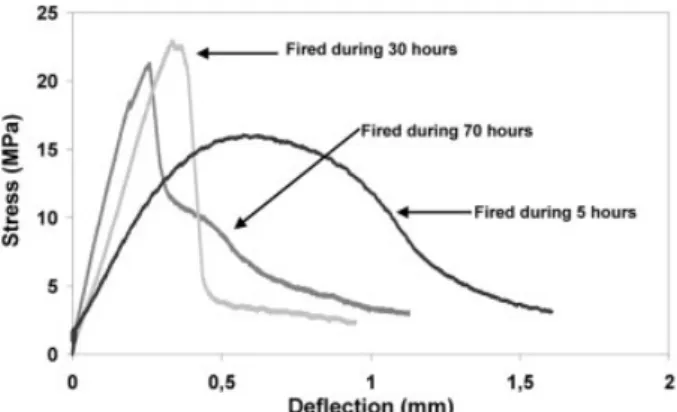
at high temperature to obtain a formed sheet with the correct geometry. An answer has been found to avoid such a visco-plastic behavior of the FRRC. It deals with increasing the duration of the firing step. Four point bending behavior curves at 900!C are presented on Fig. 4 for three firing durations. As soon as a 30h firing duration, the 900!C behavior moves from a viscoplastic one to an elastic with damage and softening one. Such a behavior evolution must be related to the microstruc-tural evolutions that take place in the refractory castable ma-trix. Thus, a long firing step of an FRRC tool allows it to keep a stable geometry during performing the SPF process.
3 Numerical simulation
3.1 Introduction
Numerical simulations by finite elements have been per-formed to evaluate the capability of the FRRC to sustain SPF solicitations. A prototype SPF tool with a 950 mm length and a 650 mm width was considered. It corresponds to an FRRC insert that is placed in a metallic tank. A meshing with tetrahedral elements supporting quadratic interpolation has been performed. A first set of simulations has been rea-lized considering a purely elastic behavior with the AbaqusJ
FEM commercial code. A second set of simulations has been performed using a Mazars damage model with the Aster FEM Fig. 1. Four point bending test behavior of the 900!C fired FRRC
castable at various testing temperatures and in the case of straight fibers.
Fig. 2. Four point bending test behavior of the 900!C fired FRRC
castable at various testing temperatures and in the case of hook-end fibers.
Fig. 3. FRRC fired at 900!C: comparison of the peak strength in four point bending for various testing temperatures and for two fiber shapes.
Fig. 4. FRRC fired at 900!C : influence of the firing duration on
code. The mechanical and thermal properties used for these different simulations are listed in Table 1.
3.2 Constitutive laws
Mazars model [6] was considered to describe the damage FFRC behavior. The material is assumed to behave elastically and to remain isotropic. IfK0is the initial stiffness matrix of the material and D the scalar damage, that ranges from 0 for the virgin material to 1 for the failed material, the following behavior law can be considered :
r ¼ K0 ð1 $ DÞ : ee ð2Þ
If thermal strainsethexist, elastic straineeis determined by the following relation :
ee
¼ e $ eth ð3Þ
whereethcorresponds to the thermal expansion.
If tensile strains are assumed to be responsible of macro-crack initiation, the equation of the loading surface is :
fðe; K; K0Þ ¼ ~ee $ KðDÞ ð4Þ
where the equivalent strain is defined as :
~ ee ¼ ffiffiffiffiffiffiffiffiffiffiffiffiffiffiffiffiffiffiffiffiffiffiffiffiffi X3 1 ðheiiÞþÞ2 v u u t ð5Þ
The parameter K(D) is equal to the largest value of the equi-valent strain ever reached by the material at the considered point in order to consider the material loading history. Initi-ally, K(D) is equal to a threshold value K0. Dtand Dcare re-spectively the tensile and compressive damage parameters. They allow to take into account the non-symmetric behavior of the FRRC. The total damage D is a weighted sum of Dtand
Dc(Eq. 7). Their evolution is given by the function defined in Eq 8. D¼ a1Dtþ acDc; Dt¼ Ftð~eeÞ; Fcð~eeÞ ð6Þ Fið~eeÞ ¼ 1 $ð1 $ AiÞK0 ~ ee $ Ai exp½Bið~ee $ K0Þ( i¼ t or c ð7Þ The use of a continuum damage model with softening leads to strain localization. The results depend on the mesh [10,11]. To avoid such a numerical problem, a regularization of equi-valent strain by a non local method has been used introducing an internal length Lc. This internal length defines an area on which the local equivalent strain will be averaged with equi-valent strain of the neighboring weighted by a function. The non local equivalent strain is calculated by considering a gra-dient formulation [7]. This model is implemented in the Aster FEM code.
4 Results
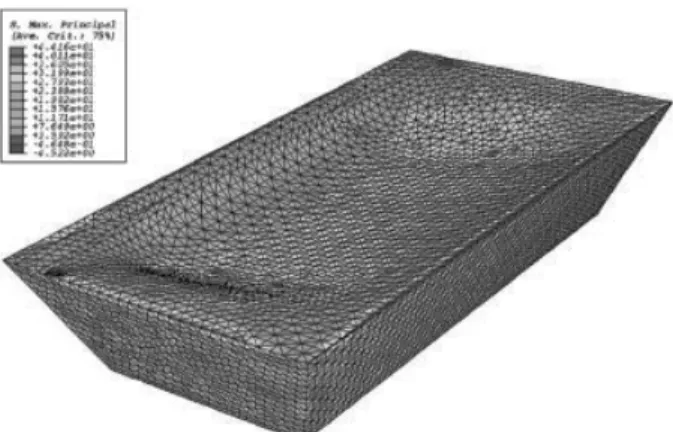
In a first time, considering a purely elastic behavior, a ther-mal simulation has been performed to determine the tempera-ture field after an extraction of the tool from the SPF press. As initial conditions, temperature is fixed to 900!C in all points of the tool. Air convection and radiative transfer are imposed as boundary conditions on the upper face of the tool. There are no boundary conditions on the other faces that are protected by the walls of the metallic chamber. An example of a calcu-lated temperature field is presented in Fig. 5. The temperature evolution is used to calculate the stress levels that are induced by thermal gradients. A result example is shown in Fig. 6 at a time of 466s after the extraction from the SPF press. The ma-ximum principal stress reaches a level of 44 MPa. On all the upper face, quite homogeneous stress levels close to 25 MPa are obtained. Such stress levels are very high when compared to the FRRC mechanical properties.
Table 1. FRRC mechanical and thermal properties used for FEM simulations Young’s modulus
[MPa]
Poisson ratio Thermal expansion
[K-1] Thermal conductivity[mW/mm.K] Specific heat[mJ/t.K] Density[t/mm3]
30 000.0 0.3 8.0 10-6 3.0 9.0 10+8 3.0 10-9
Fig. 5. Temperature field in the SPF tool at a time of 300s after the extraction from the press.
Fig. 6. Maximum principal stress field in the SPF tool at a time of 466s after the extraction from the press
A simulation of stresses generated by the sheet forming step has been performed too. An homogeneous 900!C temperature field has been taking into account for the SPF tool. A pressure of 15 bars has been applied on the upper face. Tool clamping is not considered since the FRRC tool is placed in a metallic tank that supports clamping loads. Under such conditions, the ma-ximal principal stress reaches 17.6 MPa in the FFRC tool, Fig. 7.
These results that have been obtained by considering an ela-stic behavior have shown that stresses generated by thermal gradient are more critical than stresses induced by the sheet forming step. This result is in agreement with investigations performed on SPF steel dies [12].
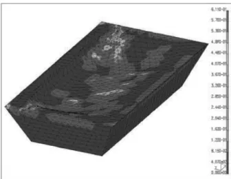
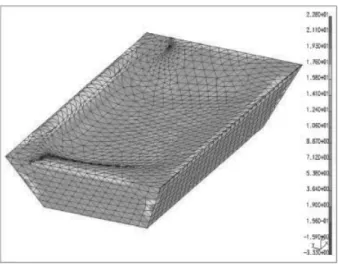
Temperature fields calculated during the step of the tool ex-traction from the press have been used to evaluate damage and stress levels in the tool. For such simulations, the Mazars mod-el with a non-local regularization has been chosen as the con-stitutive law for the FRRC. Parameter values of the model are listed in Table 2. The damage criteria is attained at a time of 30 s after the extraction of the tool from the SPF press. Damage appears first at two corners of the FFRC tool, Fig. 8. After an extraction time of 300s, damage has propagated on all the upper face, Fig. 9. The maximum damage value is close to 0.7 and an average value of 0.4 is obtained. When the extrac-tion time continues to increase, damage grows up slowly. Fig. 10 allows to observe the stress field for a 300s extraction time too. On the upper face, the average of the maximal principal stress is equal to 14MPa and is quite homogeneous. This si-mulation shows that the FRRC sustains thermal shocks induc-ed by the SPF process because of developing damage. Fiber reinforcement enables a smeared damage on all the upper face of the tool and avoids the damage localization and/or crack propagation phenomena.
5 Industrial tests
The FRRC tool considered for FEM simulations has been manufactured and tested in an industrial environment to form TA6V sheets. Fig. 11 allows to observe the upper face of the
FRRC tool after forming several TA6V sheets. Results of these industrial tests prove the capability of FRRC tools to sustain both SPF solicitations and the damage generated by thermomechanical stresses induced by the process. No macro-cracks can be detected on the tool surface. It can be considered that damage has developed in the form of diffuse microcrack-ing. Such a behavior of the FRRC tool is in good agreement with the results of FEM simulations that have been presented and discussed in this paper. Furthermore, it can be mentioned that no interactions and/or sticking phenomena have been ob-served during these industrial tests. As a consequence, a good surface quality have been obtained on the formed TA6V sheets.
6 Conclusion
The thermomechanical behavior of a FRRC for SPF tool has been presented and discussed in the 20!C to 900!C tem-perature range. It has been shown that the firing duration has a great influence on the 900!C behavior. Increasing this dura-tion avoids a viscoplastic behavior. The main steps of the SPF process have been simulated by finite element calculations.
Table 2. Parameter values of the Mazars model.
K0 Ac Bc At Bt Lc[mm]
7.0 10 – 4 1.0 1000.0 0.324 5435.0 10.0
Fig. 7. Maximum principal stress field with a 15 bars pressure ap-plied on the upper face
Fig. 8. Damage field generated by thermal gradients at a time of 30s after the tool extraction from the SPF press
Fig. 9. Damage field generated by thermal gradients at a time of 300s after the tool extraction from the SPF press
The step that deals with the extraction at high temperature of the SPF tool out of the SPF press has been detected as the most critical one. This is due to the thermal shock induced in the FRRC tool. Results of FE calculations performed with the da-mage model of Mazars have shown that the upper face of the tool undergoes damage without a catastrophic failure. This re-sult has been checked by industrial forming tests made on this tool in the case of TA6V sheets. The FRRC tool remained in-tact without any macrocracking and without any sticking be-tween the sheet and the tool. FRRC appears as a promising innovative material solution to manufacture SPF tools. Raw materials are cheap and the manufacturing process is an eco-nomic and rapid one. It’s possible to mold directly the FRRC tool to its final geometry without any machining step and with a good surface quality. Mechanical properties of the FRRC allow to FFRC tools to sustain the solicitations induced by the SPF process. Moreover, in the field of the constitutive laws, considering damage models allows to predict correctly the FRRC behavior. As a consequence, it is possible to per-form suitable sizing of SPF tools based on a FRRC materials. Lifetime limits of FRRC are still to carried out.
7 Acknowledgment
Authors gratefully acknowledge ACB, Airbus-France, Air-celle for their technical and financial supports.
8 References
1. F. Nazaret, T. Cutard, G. Bernhart, Euro SPF 04 Albi (France) 2004,139 – 144.
2. G. Bernhart, F. Nazaret, A. Martinier, C. Gao, D. Garriga-Majo, T. Cutard, P. Lours, Materials Science Forum 2004, 447 – 448, 123.
3. P. Lours, T. Cutard, G. Bernhart, C. Levaillant, International Journal of Materials and Product Technology 2001, 445.. 4. G. Bernhart, F. Nazaret, T. Cutard, Materials Science Forum
2007, 551 – 552, 37.
5. J. Mazars, Application de la me´canique de l’endommagement au comportement non line´aire et a` la rupture du be´ton de struc-ture, Paris 6 1984..
6. J. Mazars, G. Pijaudier-Cabot, Journal of Engineering Me-chanics 1989, 115, 345.
7. R. H. J. Peerlings, R. d. Borst, W. A. M. Brekelmans, J. H. P. d. Vree, International Journal for Numerical Methods in Engi-neering 1996, 39, 3391.
8. F. Nazaret, H. Marzagui, T. Cutard, Journal of the European Ceramic Society 2005, in press..
9. F. Nazaret, Caracte´risation et mode´lisation du comportement thermome´canique d’un be´ton re´fractaire renforce´ de fibres me´talliques, Ecole des Mines de Paris 2005..
10. G. Pijaudier-Cabot, A. Benallal, International Journal of So-lids and Structures 1993, 30, 1761.
11. Z. P. Bazant, J. Planas, Fracture and Size Effect in Concrete and Other Quasibrittle Materials 1998..
12. C. Y. Gao, P. Lours, G. Bernhart, Journal of materials proces-sing technology 2005, 169, 281.
Corresponding author: G. Bernhard, CROMeP (Research Center on Tools, Materials and Forming Processes), Ecole des Mines d’Albi – Campus Jarlard – Route de Teillet, 81013 Albi Cedex 09 – France, E-mail: bernhart@enstimac.fr
Fig. 10. Maximum principal stress field generated by thermal gra-dients at a time of 300s after the tool extraction from the SPF press